

Croydex WC266205E, WC266222E Installation Manual

Thank you for purchasing this Croydex product. Please follow the fixing and care instructions to
ensure your cabinet is fitted safely and retains its high q uality finish. Please retain this leaflet for
future reference.
This instruction leaflet applies to the following products:
WC266205E – Shire Stainless Steel 2 Door Illuminated Cabinet
WC266222E – Shire White 2 Door Illuminated Ca binet
IMPORTANT INSTALLATION INFO RMATION
THIS IS A CLASS 1 APPLIANCE AND MUST BE CONNECTED TO EARTH
INPUT: 220-240V ac 5A IP RATING: IP24
HAZARDOUS VOLTAGES INSIDE – DO NOT REMOVE ANY COVERS
LAMP TYPE 12V G4 HALOGEN 20W. MAXIMUM TOTAL PER CABINET = 40W
In accordance with Statutory Instrument 2004 No. 3210 - The Building (Amendment) (No.3)
Regulations 2004, any work, other than repair/replacements, in a room where there is water
(e.g. kitchen, bathroom, etc.) must be either:
• carried out by an electrician who is a member of a competent person self-certification
scheme who will certify the work complies with the Building Regulations and you do
not need to notify your local authority, or,
• carried out after prior notification to the Local Authority Building Control Department,
which has responsibility for ensuring that the work is inspected and tested.
IMPORTANT WARRANTY INFORMATION
In accordance with Statutory Instrument 2004 No. 3210 - The Building (Amendment) (No.3)
Regulations 2004, the installer must give the occupier of the premises in which this product
has been installed a certificate to confirm that the requirements of regulations 4 and 7 have
been satisfied, or the installation of this product must be inspected and tested by the Local
Authority Building Control Department who will issue a compliance certificate.
A copy of this certificate may be required for certain warranty claims. Failure to provide a
copy of the certificate may invalidate the warranty.
This does not affect your statutory rights
We recommend that you make yourself aware of the Regulations before you undertake any work and
if you require clarification you should contact your Local Authority Building Control Department.

x 2
x 2
x 2
x 4
x 4
Fig 1
Fixing Pack Contents
Fixing Pack Contents
4 x Mounting Screws, 4 x Wall Plugs
2 x Plastic Washers, 2 x Door Knob Screws,
2 x Door Knobs
Tools Required
Drill; 6.5mm masonry drill bit (6.5mm ceramic drill bit optional); Cross head screwdriver; Pencil; Spirit
level
KEEP DIY TOOLS OUT OF THE REACH OF CHILDREN
Home Safety Advice
It is recommended that two people fit the cabinet to ensure that it is fitted safely.
Always take care when using an electric drill, particularly in the bathroom. Always check for hidden
cables and pipework before drilling and take extreme care if there is any water in the working area.
It is advisable to use a residual current circuit breaker (RCCB).
Always wear suitable eye protection when drilling.
If the product is to be fitted on a ceramic tiled wall, a ceramic dr ill bit should be used. Al ways ensure
that the drill hole passes through the central tiled area rather than through the grouted area. To
prevent surface damage to the tile, mask the area around the hole with tape before drilling.
Do not strike the product with hard or sharp objects.
Do not overload the cabinet. Maximum safe working load is 15kg evenly distributed if mounted on to
a solid wall. If mounted on to a cavity wall reduce the load to 10kg evenly distributed.
Fixing Instructions
Positioning the Cabinet
1. This cabinet is rated IP24 and must only be installed with all electrical connections and
components in the Outside Zone, shown below in Fig 1.
Knob Washer Screw
Fig 3
Mounting holes
Fig 2
Outer ring
Fig 4
Lens
Insert
here
Image for reference only
Hanging the Cabinet
Note: The wall plugs supplie d are for use on solid walls only. For cav ity walls or plasterboard use specia list fixings that are available from all good DIY stores.
Fixing Instructions
1. Hold the cabinet agains t the wall in its desir ed location. Check that the
cabinet is straight and level using a spirit level. Open the doors and
mark the wall through the holes in the back of the cabinet with a penci l
(see Fig 2).
2. Using a 6.5mm mas onry drill, dri ll the ho les in the m ark ed positions to a
depth of 26mm and insert the wall plugs into the holes in the wall.
3. Hold the cabinet against th e wall and align the holes in the back of the
cabinet with the wall plugs. Insert the mounting screws through the
holes in the back of the cabinet and screw into the wall plugs.
Ensure that the domestic electrical mains supply to which the cabinet is to be connected is
4.
turned off. Connect the flexible mains supply cable on the top of the cabinet to the domestic
electrical mains supply ensuring that the Live (Brown) conductor is connected to the Live on the
domestic electrical mains supply, the Neutral (Blue) conductor is connected to the Neutral on the
domestic electrical mains supply and the Earth (Yellow/Green) conductor is connected to the
Earth/Ground on the domestic electrical mains supply. Note: connection of the product to the
domestic electrical mains supply must only be carried out by a Building Regulations Part P
certified electrician or must be checked by your Local Authority Building Control
Department.
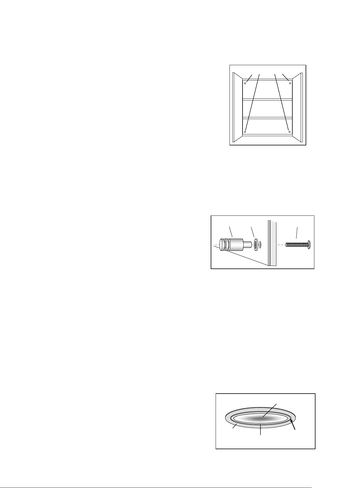
5. Position a plastic washer over the end of each door knob and
insert the end of each door knob into the holes on the mirrored
side of the doors. Secure the door knobs in place using the door
knob screws – DO NOT over-tighten the screws (see Fig 3).
Shaver Supply Unit
Note: The shaver supply unit is suitable for use with electric toothbrushes, razors and similar low
power appliances only.
Operating Instructions
Cabinet Lights
To turn the cabinet lights on or off simply use the switch located on the shaver and lighting unit
situated inside the cabinet.
Bulb Replacement
CAUTION: The bulb may become extremely hot. Allow at least 30 minutes after bulb failure
before attempting to replace the bulb.
1. Carefully remove the inner ring and lens from the
lampholder using a small flat screwdriver inserted between
the outer and inner rings (see Fig 4).
2. Carefully remove the failed G4 halogen bulb from the
lampholder (see Fig 4) then insert the pins on the
replacement G4 halogen bulb into the holes in the
Inner ring
screwdriver
 Loading...