

Croydex MM720400E, MM720500E, MM720700E, MM720300E, MM720200E Installation Manual
...
Croydex
Thank you for purchasing this Croydex product. Please follow the fixing and care instructions to ensure that
your product is fitted safely and that it retains its high quality finish. Please retain this leaflet for future
reference.
This instruction leaflet applies to the following products:
MM720500E INPUT: 220-240V ~ 190mA 40W IP 44
MM720400E INPUT: 220-240V ~ 120mA 25W IP 44
MM720700E INPUT: 220-240V ~ 160mA 35W IP 44
MM720200E INPUT: 220-240V ~ 160mA 35W IP 44
MM720600E INPUT: 220-240V ~ 120mA 25W IP 44
MM720300E INPUT: 220-240V ~ 140mA 30W IP 44
IMPORTANT INSTALLATION INFORMATION
THIS IS A CLASS 1 APPLIANCE AND MUST BE CONNECTED TO EARTH
HAZARDOUS VOLTAGES INSIDE – DO NOT OPEN SEALED UNITS
•
THERE ARE NO USER REPLACEABLE PARTS IN THE MIRROR
In accordance with Statutory Instrument 2004 No. 3210 - The Building (Amendment) (No.3) Regulations
2004, any work, other than repair/replacements, in a room where there is water (e.g. kitchen, bathroom,
etc.) must be either:
• carried out by an electrician who is a member of a competent person self-certification scheme who
will certify the work complies with the Building Regulations and you do not need to notify your local authority,
or,
• carried out after prior notification to the Local Authority Building Control Department, which has
responsibility for ensuring that the work is inspected and tested.
IMPORTANT WARRANTY INFORMATION
In accordance with Statutory Instrument 2004 No. 3210 - The Building (Amendment) (No.3) Regulations
2004, the installer must give the occupier of the premises in which this product has been installed a
certificate to confirm that the requirements of regulations 4 and 7 have been satisfied, or the installation of
this product must be inspected and tested by the Local Authority Building Control Department who will issue
a compliance certificate.
A copy of this certificate may be required for certain warranty claims. Failure to provide a copy of the
certificate may invalidate the warranty.
This does not affect your statutory rights
We recommend that you make yourself aware of the Regulations before you undertake any work and if you
require clarification you should contact your Local Authority Building Control Department.
MIR 031 R04
Fixing Pack Contents
Hang’N’Lock Wall Mounting Bracket Kit x1, Velcro Adhesive Pad x2.
(For Landscape Mounting - Screw x2, Wall Plug x2)
Tools Required
Drill; 8mm masonry drill bit (8mm ceramic drill bit optional); Cross head screwdriver; Pencil; Spirit level
(For Landscape Mounting - 6mm masonry drill bit, 6mm ceramic drill bit optional)
KEEP DIY TOOLS OUT OF THE REACH OF CHILDREN
Home Safety Advice
It is recommended that two people fit the mirror to ensure that it is fitted safely.
Always take care when using an electric drill, particularly in the bathroom. Always check for hidden
cables and pipe work before drilling and take extreme care if there is any water in the working area.
It is advisable to use a residual current circuit breaker (RCCB).
Always wear suitable eye protection when drilling.
If the mirror is to be fitted on a ceramic tiled wall, a ceramic drill bit should be used. Always ensure
that the drill hole passes through the central tiled area rather than through the grouted area. To
prevent unnecessary damage to the tile, mask the area around the hole with tape before drilling.
Do not strike the mirror with hard or sharp
objects.
Fixing Instructions
Positioning the Mirror
ZONE
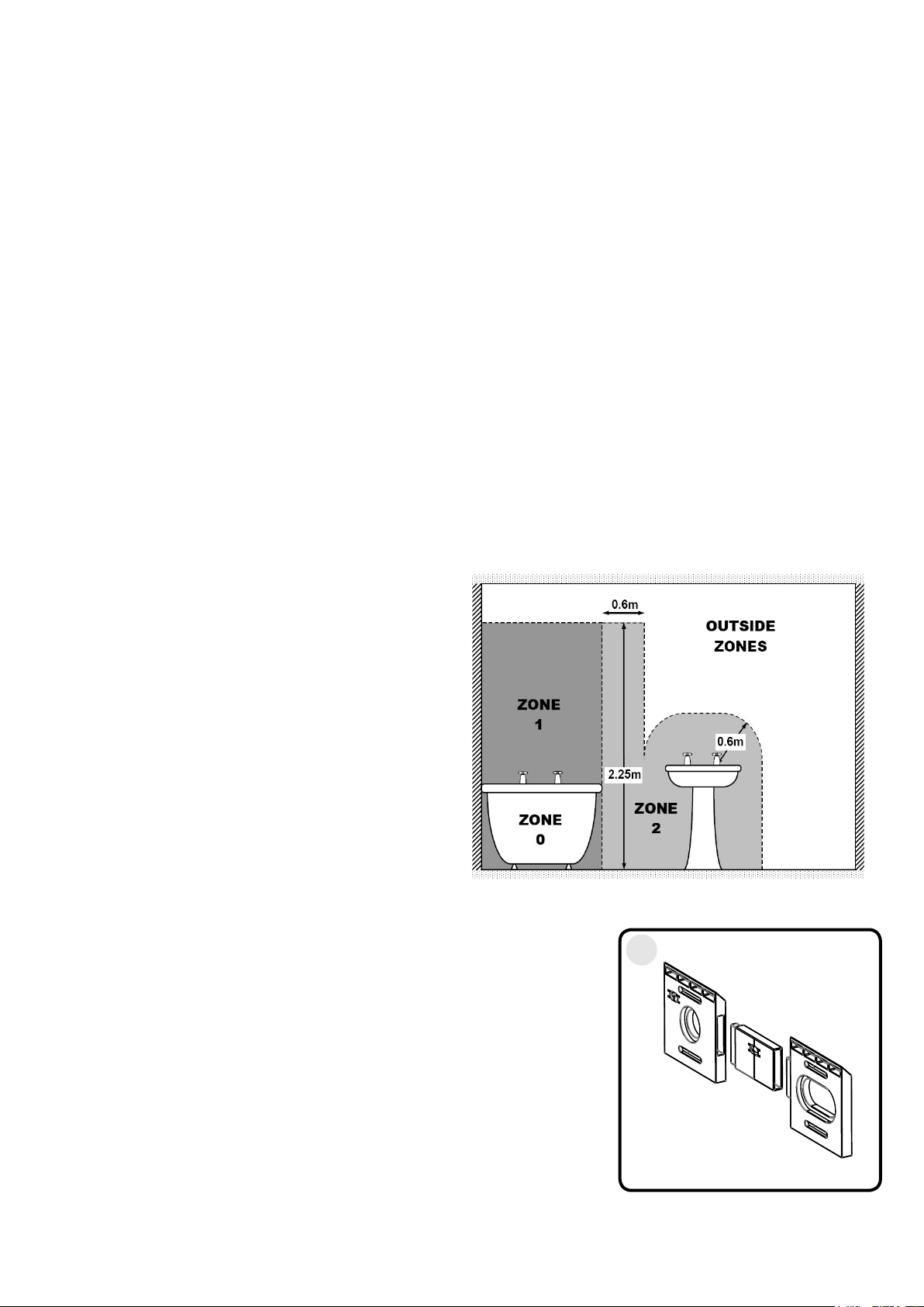
1. The mirror is rated IP44 and must only be
1
installed with the connection to the domestic
mains electrical supply in the Outside Zones, as
shown in Figure 1.
2. Ensure that the access to the domestic mains
electrical supply is located behind the intended
mounting position for the mirror.
Mounting using Hang ‘N’ Lock
1. Assemble the Hang ‘N’ Lock bracket sections making sure all parts
are slotted tightly together.
2. Place the assembled Hang ‘N’ Lock bracket onto the support slot
on the back of the mirror and hold in place. Measure the distance
from the bottom bracket to the top edge of the mirror glass. Make a
note of the ‘Bracket Distance’ as it will help you when mounting your
mirror.
Carefully hold your mirror in the desired location on the wall and
using a pencil make a reference line along the top edge of the mirror.
Use the Bracket Distance you measured earlier to create a reference
line where the bottom of your Hang ‘N’ Lock bracket will be located.
OUTSIDE
ZONES
Fig 1
1
Images for reference only.
MIR 031 R04
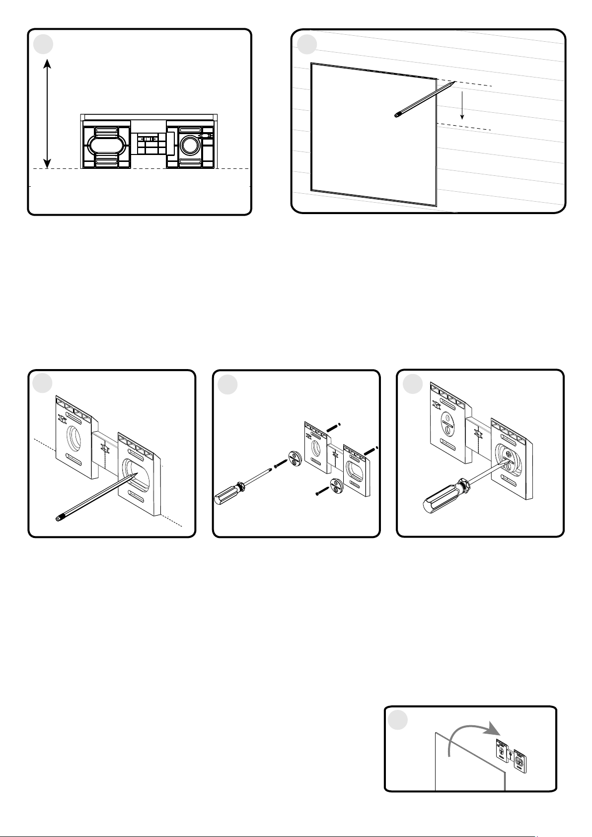
2
Bracket distance.
Image for reference only.
3. Place the bottom edge of the Hang ’N’ Lock bracket onto the lower reference line and mark a screw hole
position in each cam hole recess. Remove the bracket from the wall.
4. Drill holes to a depth of 45mm and insert the wall plugs level with the surface of the wall. (Note: if you are fitting
the product to a tiled surface, insert the wall plugs below the surface of the tile to avoid cracking the tiles). Insert
the countersink screws through the Hang ‘N’ Lock cams and loosely secure the Hang ‘N’ Lock bracket to the wall.
Top edge of mirror glass
Bottom edge of Hang ‘N’ Lock bracket
2
Bracket Distance
The wall plugs supplied are for use on solid walls only. For cavity walls or plasterboard use specialist
fixings that are available from all good DIY stores.
5. With the Hang ’N’ Lock bracket loosely attached to the wall, adjust for height and level by rotating the cams with
a flat head screwdriver, then use a Philips screwdriver to fully tighten the mounting screws, to securely fix the
bracket into position.
3
Image for reference only. Image for reference only. Image for reference only.
4
5
6. Connecting the Electrical Supply
Ensure that the domestic electrical mains supply to which the cabinet is to be connected
is turned off.
Connect the flexible mains supply cable on the mirror to the domestic electrical mains supply ensuring that:
• The Live (Brown) conductor is connected to the Live on the domestic electrical mains supply.
• The Neutral (Blue) conductor is connected to the Neutral on the domestic electrical mains supply.
• The Earth (Green/Yellow) conductor is connected to the Earth/Ground on the domestic electrical mains supply.
Note: Connection of the product to the domestic electrical mains supply must only be carried out by a Building
Regulations Part P certified electrician or must be checked by your Local Authority Building Control Department.
7. Once Step 6 has been completed safely. Hang the mirror onto the
Hang ‘N’ Lock bracket. Ensure the mirror has securely located onto the
bracket before letting go.
Proceed to Step 9 and 10.
7
MIR 031 R04
 Loading...