

Page 1
C
Specifications
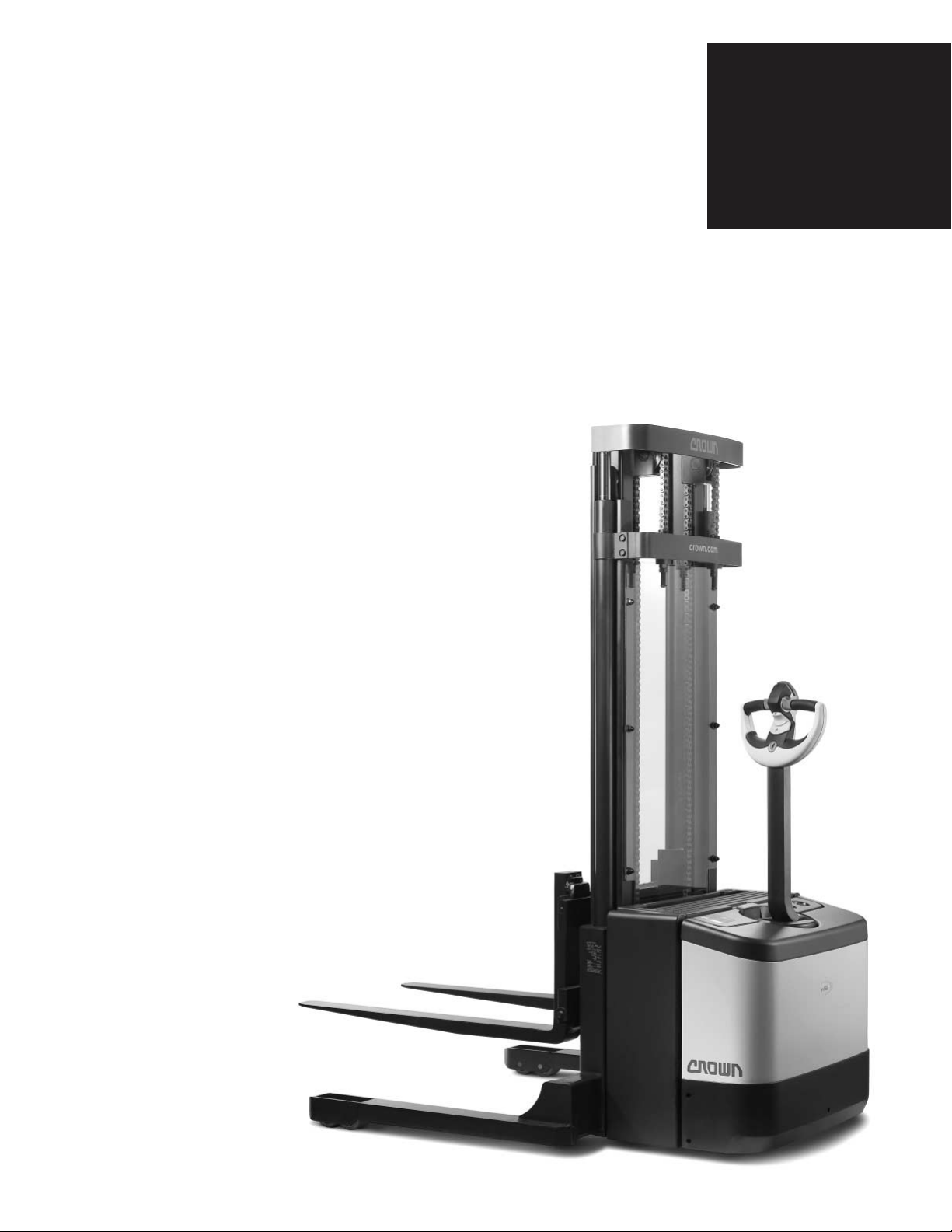
WE 2300 Series
WS 2300 Series
Walkie Stackers
WE/WS 2300
Series
Page 2
21
3.5"
1.2"
24
7
6.6"
18
20
19
28.7%
10.5%
1.4"
27"
7.5"
38
34
42"
32
27
31
23
17
47.3"
BRAKE
DRIVE
BRAKE
OVERRIDE
BRAKE
C
WE 2300 Series
Walkie Stackers
Page 3

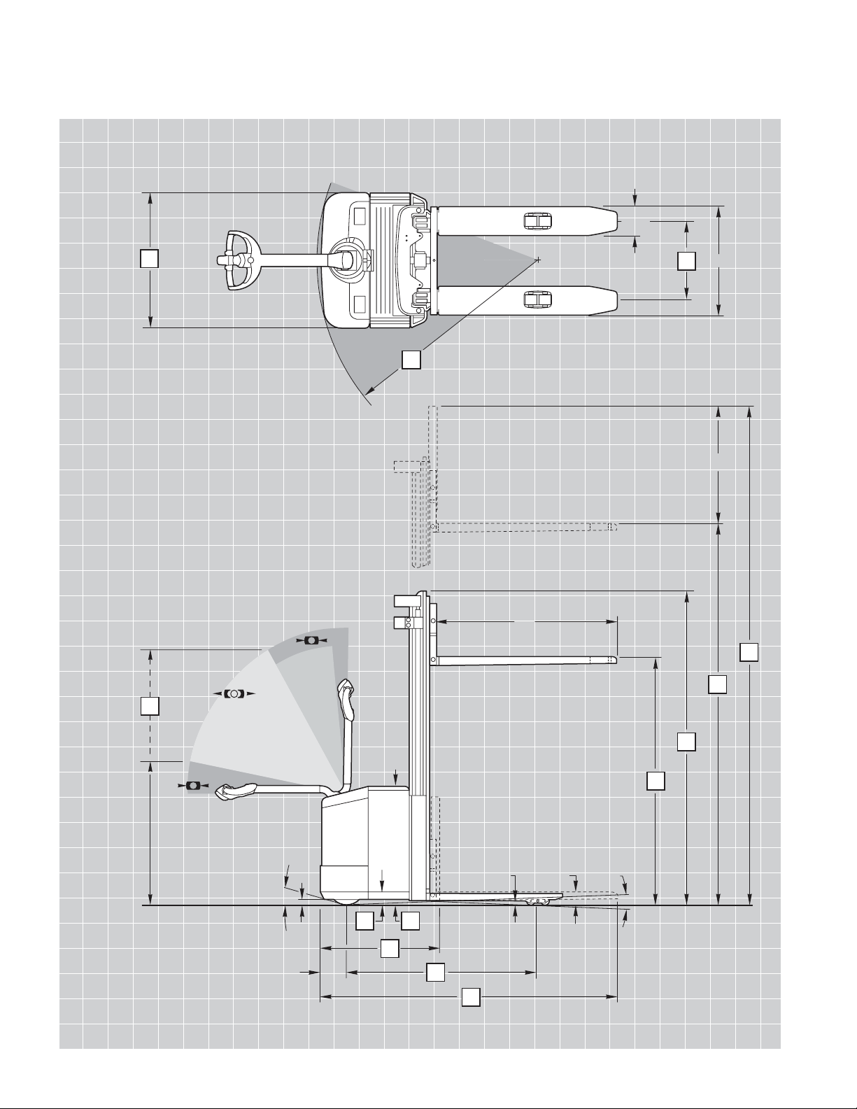
1 Manufacturer Crown Equipment Corporation
2 Model WE 2300-25 WE 2300-30
Mast Type TL TF
3 Power Electric
4 Operator Type Walkie
5 Load Capacity Max lb (kg) 2500 (1135) 3000** (1361**)
6 Load Center in (mm) 24 (600) 24 (600)
7 Wheelbase in (mm) 47 (1206) 50 (1280)
8 Weight Less Battery lb (kg) 1907 (865) 2072 (940)
13 Wheel Size Front (d x w) Vulkollan in (mm) 9.8 x 3 (250 x 75)
14 Wheel Size Rear (d x w) Vulkollan in (mm) 3.2 x 4 (82 x 100) 3.2 x 2.3 (82 x 60)
15 Additional Wheels Caster Wheel (d x w) in (mm) 5.9 x 2 (150 x 50)
16 Wheels (x=driven) Front/Rear 1x, 1/2 1x, 1/4
17 Track Width Front in (mm) 23 (587)
Rear in (mm) 15 (382)
18 Lift Height in (mm) 130 (3300) 130 (3300)
19 Free Lift w/o Load Backrest lb (kg) 6 (150) 68 (1720)
20 Collapsed Height in (mm) 84 (2130) 84 (2130)
21 Extended Height* w/o Load Backrest in (mm) 147 (3730) 147 (3730)
22 Load Backrest Size in (mm) 47.3 (1202) H x 32.7 (832) W
23
Tiller Arm Height
in Drive Position
Min/Max in (mm) 31 (780) / 48 (1220)
24 Battery Comp’t Floor Ht in (mm) 3.4 (85)
25 Lowered Fork Height in (mm) 3.5 (90)
27 Power Unit Height in (mm) 29.75 (756)
28 Fork Lengths in (mm) 42 (1067)
29 Fork Dimensions Thickness in (mm) 2 (50)
Width in (mm) 7.5 (190)
30 Width Across Forks in (mm) 27 (686)
31 Headlength in (mm) 29 (730) 30 (753)
32 Overall Length at fork length 42" in (mm) 71 (1803) 72 (1829)
34 Overall Width in (mm) 33.5 (850)
35 Fork Carriage Width in (mm) 27 (680)
36 Ground Clearance w/Load Below Mast in (mm) 1.4 (35)
37 Center Wheelbase in (mm) 1.2 (30)
38 Turning Radius in (mm) 55 (1400) 58 (1475)
40 Travel Speed
w/wo Load
mph (km/h) 3.3 / 3.7 (5.3 / 6.0)
41 Lift Speed
w/wo Load
fpm (m/s) 31 / 51 (.16 / .26) 28 / 43 (.14 / .22)
42 Lowering Speed
w/wo Load
fpm (m/s) 71 / 43 (.36 / .22) 71 / 43 (.36 / .22)
43 Gradeability
w/wo Load, 30 min Rating
% 3 / 9 3 / 8
44 Maximum Gradeability
w/wo Load, 5 min Rating
% 9 / 17 8 / 17
45 Service Brake Electric
46 Maximum Battery Box L x W x H in (mm) 8.5 x 32.5 x 24.7 (216 x 827 x 627)
47 Battery Voltage (Nominal
Capacity 6 Hour Rating)
V/Ah 24 / 195
48 Type of Controller Drive Transistor
49 Battery Weight lb (kg) 644-712 (293-323)
WE 2300 Series
Specifications
General Information
Tires
Dimensions
PerformanceBattery
* Subtract 32" (810 mm) from free lift; add 32" (810 mm) to extended height if optional 47.3" (1202 mm) high load backrest is required.
** Up to 110" (2800 mm), 2910 lb up to 130" (3300 mm)
English conversions are approximations. Metric conversions should be done to find true values.
Page 4

WE 2300 Series
Technical Information
Standard Equipment
1. Four-point suspension with
centrally located handle
2. Traction speed control
(MOSFET)
3. Variable traction speed
forward and reverse
4. One-speed lift, two-speed
lower
5. Electric brake
6. Brake override
7. Key switch
8. Horn
9. Compound drive and lift
motor
10.
Emergency power
disconnect
11. Battery connector SB-175
12. Reversing button
13. Hour meter
14. Vulkollan tires
15. 27" x 42" fork configuration
Optional Equipment
1. Pivoting tandem load
wheels 3.2" x 2.3"
(WE 2300-25 only)
2. Battery compartment rollers
3. Battery discharge indicator
with low battery lift interrupt
and hour meter
4.
Freezer corrosion conditioning,
continuous -30° C / -22° F,
intermittent - 40° C / - 40° F
5. Load backrest
6. Maintenance-free battery
pack
Electrical System
24-volt electrical system
incorporating:
1. Transistor “MOSFET”
controller, microprocessor
controlled with on-board
service diagnostic capability.
This transistor controller
provides many benefits
such
as maximum energy
efficiency,
reduced
maintenance and infinite
speed control capability.
Fault Monitoring System:
Through a fault flash code
signaled by an LED, 17
detectable faults can be
recognized. Using an optional
hand set, faults can be displayed
digitally. Controller settings are
programmable. Functional
tests of components are also
possible. Incorporates storage
register for fault history that can
be interrogated by service
personnel.
2. Heavy-duty drive and lift
motors provide high reliability
and efficiency.
3. Electric panel with swing-out
feature, allows good accessibility and serviceability to
the distribution panel and all
other electrical components.
4. Emergency disconnect is
easily accessible from all
operating positions.
5.
Solid-state switching ensures
high component reliability.
6. Control and power circuits
are fused. Distribution panel
and controller are shortcircuit protected.
7. All wiring is color coded.
Hydraulic System
1. Heavy-duty compound
motor and gear pump
selected for optimum lift
performance and low noise.
2. Control block houses
proportional pressure
compensated flow control
valve, check valve, relief
valve and direction control
valve to select lower
function. The proportional
valve ensures smooth load
handling. Single speed lift
and two speed lowering is
available to the operator.
3. Cylinder rods are hard-plated
chrome with polyurethane
seals.
4. Relief valve tuned to capacity
protects all components in
the hydraulic system.
Drive Unit/Brake
Heavy-duty gear box with
helical spur input gear for low
noise emission. Drive unit is
equipped with an electromagnetic brake, spring applied,
electrically released. The brake
is activated by the control
handle position.
Frame/Pivoting Carriage
Frame and Articulated Truck
Suspension system (ATS) are
of a rugged design ensuring
minimum deflections during
operation. Modular pivoting
carriage design ensures excellent
traction, optimum truck stability
and minimum steering effort in
all load conditions. Easy serviceability
of all components in
power unit and simple adjustment to compensate for tire
wear is possible. Single swingout door design allows easy
access to all components.
Mast
High visibility two- and threestage mast design features
nested I-beams and canted
rollers. Lift cylinders are positioned in outer I-beam profile for
best visibility through mast and
clear view onto fork tips during
load handling. Standard
equipment includes full-free lift
for two- and three-stage mast.
Mast cushioning between
stages ensures smooth
operation. Heavy-duty mast
and chain rollers are sealed
and lubricated for life. Easy
access to carriage rollers.
Operator Controls
The robust X10™ control
handle is designed to allow for
an optimum turning radius with
low steer effort. All control
buttons can be operated with
either hand and can be
accessed with minimum hand
and wrist movement. The horn
buttons are integrated in the
hand grips. An ergonomic
forward/reverse thumb wheel
allows for precise maneuvering.
Depending on conditions and
operator experience, maximum
travel speed can be reduced
via the rabbit/turtle switch.
Exclusive brake override allows
slow speed travel with the
handle near vertical. This feature
improves maneuverability in
tight areas.
Battery
Removable side panels and top
hinged cover allow easy access
to battery, as well as battery
change in three directions,
either side or top lift out.
Compartment rollers are fitted
as an option.
Other Options
1. Audible travel alarm
2. Flashing lights
Safety considerations and
dangers associated with audible
travel alarms and flashing lights
include:
• Multiple alarms and/or lights
can cause confusion.
• Workers ignore the alarms
and/or lights after day-in and
day-out exposure.
• Operator may transfer the
responsibility for “looking out”
to the pedestrians.
• Annoys operators and
pedestrians.
Dimensions and performance
data given may vary due to
manufacturing tolerances.
Performance is based on an
average size vehicle and is
affected by weight, condition of
truck, how it is equipped and
the conditions of the operating
area. Crown products and
specifications are subject to
change without notice.
Page 5

19
20
18
21
4"
1.6"
6.6"
7
39
1.4"
17.6%
28.7%
32
17 343330
24
28
30
34
27
31
38
35
47.3"
23
BRAKE
DRIVE
BRAKE
OVERRIDE
BRAKE
C
WS 2300 Series
Walkie Stackers
Page 6

WS 2300 Series
Specifications
1 Manufacturer Crown Equipment Corporation
2 Model WS 2300-40 WS 2300-40
Mast Type TL/TF TT
3 Power Electric
4 Operator Type Walkie
5 Load Capacity Max lb (kg) 4000 (1815) 4000* (1815*)
6 Load Center in (mm) 24 (600) 24 (600)
7 Wheelbase in (mm) 51 (1300) 51 (1300)
8 Weight Less Battery lb (kg) 2072 (940) 2282 (1035)
13 Wheel Size Front (d x w) Vulkollan in (mm) 9.8 x 3 (250 x 75)
14 Wheel Size Rear (d x w) Vulkollan in (mm) 3.3 x 2.8 (85 x 70)
15 Additional Wheels Caster Wheel (d x w) in (mm) 5.9 x 2 (150 x 50)
16 Wheels (x=driven) Front/Rear 1x, 1/4
17 Track Width Front in (mm) 23 (587)
Rear in (mm) 46, 54 (1167, 1370)
18 Lift Height in (mm) 128 (3250) 160 (4050)
19 Free Lift ** TL lb (kg) 4 (100) na
w/o Load Backrest
TF/TT** lb (kg) 62 (1575) 51 (1305)
20 Collapsed Height in (mm) 84 (2130) 73 (1860)
21 Extended Height* w/o Load Backrest in (mm) 151 (3825) 182 (4625)
Outrigger Height in (mm) 4 (100)
22 Lowered Fork Height in (mm) 1.6 (40)
23
Tiller Arm Height
in Drive Position
Min/Max in (mm) 31 (780) / 48 (1220)
24 Battery Comp’t Floor Ht in (mm) 3.4 (85)
27 Power Unit Height in (mm) 29.75 (756)
28 Fork Lengths in (mm) 30, 36, 42, 45, 48 (760, 912, 1067, 1167, 1219)
29 Fork Dimensions Thickness in (mm) 1.6 (40)
Width in (mm) 4 (100)
30 Width Across Forks Adjustable Min/Max in (mm) 10 (253) / 31.1 (790)
31 Headlength in (mm) 31 (783) 32 (808)
32 Overall Length at fork length 42" in (mm) 73 (1850) 74 (1875)
33 Inside Straddle in (mm) 42, 50 (1067, 1270)
34 Overall Width Front in (mm) 33 (850)
Rear in (mm) 50, 58 (1267, 1470)
35 Fork Carriage Width in (mm) 32.5 (825)
36 Ground Clearance w/Load Below Mast in (mm) 1.4 (35)
37 Center Wheelbase in (mm) 1.6 (40)
38 Turning Radius in (mm) 59 (1490)
39 Length Over Outrigger in (mm) 60 (1535)
40 Travel Speed
w/wo Load
mph (km/h) 3.3 / 3.7 (5.3 / 6.0)
41 Lift Speed
w/wo Load
fpm (m/s) 26 / 43 (.13 / .22)
42 Lowering Speed
w/wo Load
fpm (m/s) 71 / 39 (.36 / .20)
43 Gradeability
w/wo Load, 30 min Rating
%2 / 8
44 Maximum Gradeability
w/wo Load, 5 min Rating
% 7 / 17
45 Service Brake Electric
46 Maximum Battery Box L x W x H in (mm) 8.5 x 32.5 x 24.7 (216 x 827 x 627)
47 Battery Voltage (Nominal
Capacity 6 Hour Rating)
V/Ah 24 / 195
48 Type of Controller Drive Transistor
49 Battery Weight lb (kg) 644-712 (293-323)
General Information
Tires
Dimensions
Performance
Battery
* Up to 144" (3658 mm), 3548 lb up to 160" (4050 mm)
** Subtract 26" (665 mm) (WS 2300-40 TF/TT) from free lift;
Add 26" (665 mm) (WS 2300-40 TL/TF/TT) to extended height if option 47.3" (1202 mm) high load backrest is required.
English conversions are approximations. Metric conversion should be done to find true values.
Page 7

WS 2300 Series
Technical Information
Standard Equipment
1. Four-point suspension with
centrally located handle
2. Traction speed control
(MOSFET)
3. Variable traction speed
forward and reverse
4. One-speed lift, two-speed
lower
5. Electric brake
6. Brake override
7. Key switch
8. Horn
9. Compound drive and
lift motor
10. Emergency power
disconnect
11. Battery connector SB-175
12. Reversing button
13. Hour meter
14. Vulkollan tires
Optional Equipment
1. Battery compartment rollers
2. Battery discharge indicator
with low battery lift interrupt
and hour meter
3.
Freezer corrosion conditioning,
continuous -30° C / -22° F,
intermittent - 40° C / - 40° F
4. Load backrest
5. Maintenance-free battery
pack
6. Sideshift
Electrical System
24-volt electrical system
incorporating:
1. Transistor “MOSFET”
controller, microprocessor
controlled with on-board
service diagnostic capability.
This transistor controller
provides many benefits
such as maximum energy
efficiency, reduced
maintenance and infinite
speed control capability.
Fault Monitoring System
Through a fault flash code
signaled by an LED, 17
detectable faults can be
recognized. Using an optional
hand set, faults can be displayed
digitally. Controller settings are
programmable. Functional
tests of components are also
possible. Incorporates storage
register for fault history that can
be interrogated by service
personnel.
2. Heavy-duty drive and lift
motors provide high reliability
and efficiency.
3. Electric panel with swing-out
feature, allows good accessibility and serviceability to
the distribution panel and all
other electrical components.
4. Emergency disconnect is
easily accessible from all
operating positions.
5. Solid-state switching ensures
high component reliability.
6. Control and power circuits
are fused. Distribution panel
and controller are shortcircuit protected.
7. All wiring is color coded.
Hydraulic System
1. Heavy-duty compound
motor and gear pump
selected for optimum lift
performance and low noise.
2. Control block houses
proportional pressure
compensated flow control
valve, check valve, relief
valve and direction control
valve to select lower
function. The proportional
valve ensures smooth
load handling. Single speed
lift and two speed lowering
is available to the operator.
3. Cylinder rods are hard-plated
chrome with polyurethane
seals.
4. Relief valve tuned to capacity
protects all components in
the hydraulic system.
Drive Unit/Brake
Heavy-duty gear box with
helical spur input gear for low
noise emission. Drive unit is
equipped with an electromagnetic brake, spring applied,
electrically released. The brake
is activated by the control
handle position.
Frame/Pivoting Carriage
Frame and Articulated Truck
Suspension system (ATS) are
of a rugged design ensuring
minimum deflections during
operation. Modular pivoting
carriage design ensures excellent
traction, optimum truck stability
and minimum steering effort in
all load conditions. Easy serviceability of all components in
power unit and simple adjustment to compensate for tire
wear is possible. Single swingout door design allows easy
access to all components.
Mast
High visibility two- and threestage mast design features
nested I-beams and canted
rollers. Lift cylinders are positioned in outer I-beam profile
for best visibility through mast
and clear view onto fork tips
during load handling. Standard
equipment includes full-free lift
for two- and three-stage mast.
Mast cushioning between
stages ensures smooth
operation. Heavy-duty mast
and chain rollers are sealed
and lubricated for life. Easy
access to carriage rollers.
Fork Carriage
WS 2300 Series features a
standard 32" wide ITA Class II
fork carriage. Forks are
adjustable from 10" to 31".
Standard fork lengths are
30", 36", 42" 45" and 48".
Operator Controls
The robust X10™ control handle
is designed to allow for an
optimum turning radius with low
steer effort. All control buttons
can be operated with either
hand and can be accessed
with minimum hand and wrist
movement. The horn buttons
are integrated in the hand grips.
An ergonomic forward/reverse
thumb wheel allows for precise
maneuvering. Depending on
conditions and operator
experience, maximum travel
speed can be reduced via the
rabbit/turtle switch. Exclusive
brake override allows slow
speed travel with the handle
near vertical. This feature
improves maneuverability in
tight areas.
Battery
Removable side panels and top
hinged cover allow easy access
to battery, as well as battery
change in three directions,
either side or top lift out.
Compartment rollers are fitted
as an option.
Other Options
1. Audible travel alarm
2. Flashing lights
Safety considerations and
dangers associated with audible
travel alarms and flashing lights
include:
• Multiple alarms and/or lights
can cause confusion.
• Workers ignore the alarms
and/or lights after day-in and
day-out exposure.
• Operator may transfer the
responsibility for “looking out”
to the pedestrians.
• Annoys operators and
pedestrians.
Dimensions and performance
data given may vary due to
manufacturing tolerances.
Performance is based on an
average size vehicle and is
affected by weight, condition of
truck, how it is equipped and
the conditions of the operating
area. Crown products and
specifications are subject to
change without notice.
Page 8

Because Crown is continually improving its products,
specifications are subject to change without notice.
Crown, the Crown logo, the color beige, the
Momentum symbol and The X10 Handle are
trademarks of Crown Equipment Corporation.
Copyright 2004-2007 Crown Equipment Corporation
SF14404 Rev. 5/07
Printed in U.S.A.
Crown Equipment Corporation
New Bremen, Ohio 45869 USA
Tel 419-629-2311
Fax 419-629-3796
crown.com
You can count on Crown to build lift trucks
designed for safe operation, but that’s
only part of the safety equation. Crown
encourages safe operating practices through
ongoing operator training, safety-focused
supervision, maintenance and a safe working
environment. Go to crown.com and view our
safety section to learn more.
C
 Loading...