

Page 1
C
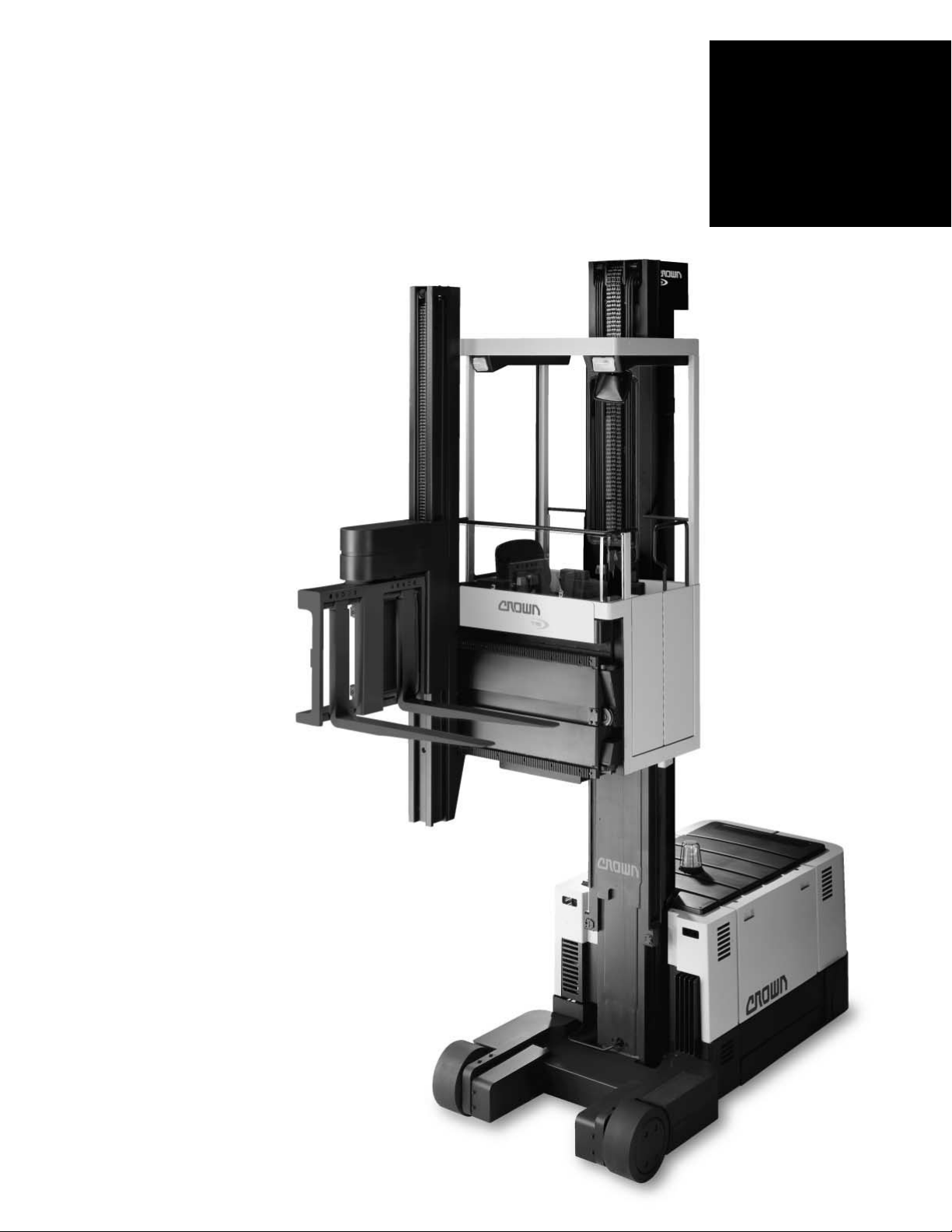
Specifications
Series TS
Turret
Sideloader
Series
TS
Page 2
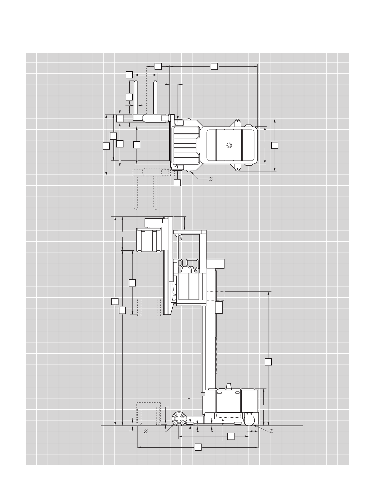
6"x 2"
48"
9"
4"
9.5"
42"
45.8"
3.6" Top of Guide
wheel to floor
2" Fork
3" 15"X 8"
2"
9.9" Battery to floor
11.6"
13"X 5.5"
17
16
16
18
19
21
20 23
25
14
12"
12
10
22
24
11
15
13
0.8"
C
Series TS
Turret
Sideloader
Page 3

Series TS
Specifications
1 Manufacturer Crown Equipment Corporation
2 Model 40TS
3 Load Capacity* 24" Load Center lb 4000
4 Power Electric 72-Volt (2 x 36 Volt)
5 Operator Type Sitdown Rider Turret Sideloader
6 Tire Type Load/Drive Poly/Poly
7 Wheels (x = driven) Load/Drive 2/2x
8 Truck Weight Less Battery lb 11,000 - 14,200
10 Lift Height Lift Height See Chart
11 Collapsed Height Overall See Chart
12 Extended Height Overall See Chart
13 Auxiliary Lift in 81
14 Load Wheel Overall Width (OAW) Available in 1" increments in 48 to 72
15 Operator Compartment Width With Any Carriage Width in 48
16 Carriage and Cab Width in 48 58
17 Clear Aisle - in 1" increments Carriage and Total Sideshift in 56 - 69 66 - 79
18 Sideshift Per Side Available in .5" increments in 4 to 10.5
19 Forks L x W x T in 30, 36, 37, 42, 45, 48, x 4 x 2
20 Load Handler Length Standard in 28.3
Available in 3" increments in From 30.3 to 54.3
21 Outside Fork Spread
For Load Handler from 28.3 to 54.3
in 15.3 to 29.3
For Load Handler from 36.3 to 54.3
in 15.3 to 43.3
For Load Handler from 48.3 to 54.3
in 15.3 to 53.8
22
Overall Length with 28.3" Load Handler
C Battery Compartment in 154
D Battery Compartment in 157.5
23 Headlength C Battery Compartment in 109.9
D Battery Compartment in 113.4
24 Wheelbase C Battery Compartment in 88.8
D Battery Compartment in 92.3
25 Width across Guide Roller Available in .25" increments in 1.25 - 8.75 greater than item 14
30 Speed Travel mph See Technical Information
31 Speed Lift Primary Mast Empty/Loaded fpm 80/64
Auxiliary Mast Empty/Loaded fpm 70/55
32 Speed Lower Primary Mast Empty/Loaded fpm 80/80
Auxiliary Mast Empty/Loaded fpm 40/70
33 Pivot Speed 180 degree rotation 7 seconds
34 Traverse Speed Inches per second 8
40 Battery (Two Required) C Compartment D Compartment
Max Battery Size in 15.88 x 38.38 x 31 high 18 x 38.69 x 31 high
Min Weight/Max Amp lb/Ah 1770/930 2085/1085
Number of Plates/Total Kwh 13/64.4 15/75.2
50 Brakes Number Load/Drive 2/2
Load Wheel Brakes Dual Disc
Drive Unit Brakes Dual Drum
General Info
Dimensions
Battery
*Contact factory. Capacity may be subject to derating.
Derating is dependent upon a combination of: load center, load wheel spread, 180° traverse/sideshift, battery compartment size,
lift height, travel speed and height of Auxiliary Mast.
Performance
Page 4

Series TS
Specifications
10 Lift Height in 219 231 243 255 267 279 291 303 315 327 339 351 363
Free Lift (TN)* in 84 84 84 84 84 84 84 84 84 84 84 84 84
Free Lift (TF)** in 83 89 95 101 107 113 119 125 131 137 143 149 155
11 Collapsed Height in 125 131 137 143 149 155 161 167 173 179 185 191 197
12 Extended Height in 261 273 285 297 309 321 333 345 357 369 381 393 405
Mast
10 Lift Height in 375 387 399 411 423 435 447 459 471 483 495 507
Free Lift (TN)* in 84 84 84 84 84 84 84 84 84 84 84 84
Free Lift (TF)** in 161 167 173 179 185 191 197 203 209 215 221 227
11 Collapsed Height in 203 209 215 221 227 233 239 245 251 257 263 269
12 Extended Height in 417 429 441 453 465 477 489 501 513 525 537 549
Mast
* Auxiliary lift only.
** Including auxiliary lift.
Note: Battery removal from left side.
Standard Equipment
1. 72-volt fused electrical system.
2. SCR controlled lift and drive
motors.
3. Electric power steering.
4. Microprocessor controlled.
5. 350-amp battery connector.
6. Emergency power disconnect.
7. Color-coded wiring.
8. Chain slack sensors.
9. Hour meters independently
recording key on, traction,
lift, steer and accessories.
10. Start-up time and run time
diagnostics.
11. Diagnostic history with
optional service terminal.
12. Battery discharge indicator
with lift interrupt.
13. Maximum travel speed
programmed to meet the
application’s specs.
14. Gradual reduction in maximum travel speed as primary
lift is increased.
15. Swivel seat with height
adjustment.
16. Hinged cab door.
17. Key switch.
18. Horn.
19. Two-speed fan.
20. Cab light.
21. Work lights.
22. Rear view mirror.
23. Flashing light.
24. Storage pockets.
25. Infinite hydraulic control of
raise/lower, traverse and pivot.
26. Manual lowering valve
located in power unit.
27. Solid four-point suspension.
28. Rigid tubular mast.
29. Third mast chain.
30. 2-3/4" diameter battery
rollers.
31. Dual drive units.
32. Four-wheel braking automatically switched to two-wheel
at slower speeds.
Optional Equipment
1. Wire guidance.
2. Rail guidance.
3. End of aisle control system.
4. Extended load handler
lengths and carriage widths.
5. Extended Auxiliary Lifting
heights.
6. Programmable fork height
limits with overrides.
7. Non-marking tires.
8. Power source and mounting
brackets for CRT.
9. Fire extinguisher.
10. Cold conditioning.
11. Additional work lights.
12. Service Terminal.
Series TS
Technical Information
Page 5

Series TS
Technical Information
Travel Speeds
Maximum travel speed on guidance is: 6 mph (528 fpm) to 156"
fork elevation. Gradual speed
reduction to 1 mph at 372", 1
mph above 372" fork elevation.
Travel speed is limited to 1 mph
under any of the following
conditions:
1. Forks are elevated above
12" on the auxiliary mast.
2. Forks are not at full pivot.
3. Load handler traversesideshift are not at clear-aisle
travel position.
Travel speed is disabled under
any of the following conditions:
1. Forks are not at full pivot and
above 240".
2. Not on guidance and above
240".
3. Not on guidance, forks not at
clear-aisle travel position above
93" and steering turned greater
than 10°.
4. The TN travel speed is disabled, whenever out of guided
aisle and primary lift is raised,
unless otherwise specified.
Travel speeds not on guidance
are less than those on guidance
at elevated fork heights.
Wheels and Tires
Large, high-load capacity polyurethane press-on tires. Load
wheels - 15" diameter x 8" wide.
Drive Wheels - 13" diameter x
5.5" wide. Guide Wheels - 6" dia-
meter x 2" wide molded-on hub,
non-press-on.
Suspension
Four-point solid suspension with
long wheel base and wide spread
of load and drive wheels improve
truck capacity, reduce effect of
uneven floors, and improve floor
load distribution.
Forks--Fork Carriage--Turret
Carriage
Forks are incrementally adjustable.
Fork carriage pivots through 180º
permitting pickup and deposit
from either side or front. Cylinders
are equipped with hydraulic cushion stops to automatically reduce
speed at end of pivot. Cross-over
relief valves reduce excess pressure should forks be force-pivoted.
Pivot lock engages at full-rotated
position to prevent drift.
lights, palm switch light, open cab
door warning light, master servicerequired light, service calibration
light, wire guidance field strength
light (optional), wire guidance
switch and status lights (optional),
parking brake switch with status
light, fork height limit override
button with light, and discharge
indicator with low voltage lift interrupt to reduce truck and battery
maintenance.
Controls permitting emergency
fork movement are located below
the hinged arm rest pad. Horn
button, primary power emergency
disconnect and power key are
provided. All controls are located
convenient to the operator.
Storage pockets for work sheets
are provided. A two speed fan,
cab light and work lights front and
back, are located in the overhead
consoles.
Primary Mast
Elevated load sway due to mast
twisting, plus forward and side
bowing are minimized through
the use of closed cross-section
mast construction. Rolled “I”
beams continuously welded to a
flat and a formed plate create a
full length, deep cross-section
mast capable of resisting front
and side loading equally well. Lift
cylinders, hoses, cables and
chains within the mast are readily
accessible for service. Built-in
sensors detect slack chain and
shut down primary lower, auxiliary
lower, pivot and traverse functions.
Drive Units-Steering
Steerable dual drive units with
fixed mounted traction motors
minimize wear and maintenance
on electrical cables. Full electrical
power steering uses servomotors
for turning the drive wheels. Drive
wheels are automatically centered
on trucks equipped with aisleguide rollers.
Brakes
Two force levels of mechanical
braking provide smooth stopping.
This is achieved by the truck
automatically switching from four
wheel to two wheel braking at
slower travel speeds. Braking can
also be accomplished by proportional plugging which permits the
operator to control rate of deceleration when a greater stopping
distance is acceptable.
Electrical
Heavy duty 72 volt electrical
power system reduces current
requirements for improved efficiency. SCR controlled lift and
Auxiliary Mast
Turret carriage with forks can be
elevated on the auxiliary mast to
permit stacking close to the ceiling. Operator can view the load
from the underside at full auxiliary
lift to aid load placement. Lift
cylinder, hydraulic hoses and
electrical cables are protected
within the profile of the structure,
or behind removable covers. Vertical side alignment of the mast is
maintained by gear racks and
pinions. Lowering of auxiliary and
primary lift system will stop if
chains become slack.
Traverse and Sideshift
Traverse movement of the auxiliary mast and side movement of
the sideshift carriage are automatically sequenced, requiring
only one operator control. Full
sideshift travel with built-in limits
is brought to a smooth stop by
hydraulic cushions. Withdrawal of
forks from the side-extended position automatically stops at the
travel position.
Operator Cab and Controls
Adjustable operator’s seat pivots
35° from a full side position toward
a forward position to provide visibility to the front, rear or either side.
Lever controls permit all load
handling functions to be infinitely
controlled. Left hand control is
used for primary and auxiliary
raise and lower. Right hand pivot
and traverse controls can be
simultaneously operated for
pivoting the load in a minimum
amount of space. Movement of
the sideshift carriage is automatically sequenced to the traverse
control. Integrated palm-pressure
buttons in the control knobs
require the operator to keep his
hands within the compartment
during any load handling function.
Programmable fork height limits
are available for raise and lower.
Both lower and one raise limit can
be overridden by the operator.
Steer wheel position indicator is
located next to the steering arm.
Forward and reverse travel is controlled by a directional selector
and accelerator pedal. The truck
can be stopped by activation of
foot-operated brake, proportional
plugging, parking brake, emergency disconnect or power key.
A control and feed back display
include indicator lights for forward
and reverse travel direction, load
handler clear aisle travel position
drive motors. Each controller
provides current limiting motor
protection in addition to the fuses.
Two on-board micro-computers
are integrated into the truck to
provide maximum load handling
through-put and smooth truck
performance. Serial data link
communications between the
elevated cab and the lower power
unit minimizes the number of
electrical conductors through the
mast. Long life solid state encoders and LVDT are used in
place of potentiometers. Travel
speed is sensed and regulated to
precise rate. Height sensor provides input for a programmed
gradual reduction in maximum
allowable travel speed as the primary lift is elevated. Maximum lift
and lower speeds are reduced
near full lift and lower to provide a
soft stop. On-board software includes truck calibration, system
diagnostics and trouble isolation
capabilities accessible by an
optional plug-in terminal.
Hydraulics
Maximum lowering speed is limited by pressure-compensating
flow controls and velocity fuses.
Integrated hydraulic cylinder
cushions bottom stop when lowering. All lift cylinder rams are
plated. Primary mast emergency
lowering valve and load handler
emergency power switch are
located in the power unit.
Other Options
1. Audible Travel Alarm.
2. Contact factory for additional
options.
Safety considerations and dangers
associated with audible travel
alarms include:
• Multiple alarms can cause
confusion.
• Workers ignore the alarms
after day-in and day-out
exposure.
• Operator may transfer the
responsibility for “looking out”
to the pedestrians.
• Annoys operators and
pedestrians.
Dimensions and performance
data given may vary due to manufacturing tolerances. Performance
is based on an average size vehicle
and is affected by weight, condition of truck, how it is equipped
and the conditions of the operating
area. Crown products and specifications are subject to change
without notice.
Page 6

SF12182 Rev. 4/03
The Momentum symbols are a trademark of
Crown Equipment Corporation.
C
Crown Equipment Corporation
New Bremen, Ohio 45869 USA
Tel 419-629-2311
Fax 419-629-3796
crown.com
Because Crown is continually improving its products,
specifications are subject to change without notice.
Copyright 1994 Crown Equipment Corporation
Printed in U.S.A.
 Loading...