

Page 1
C
SR 5285H
Specifications
SR 5285H Series
Reach Truck
Series
Page 2
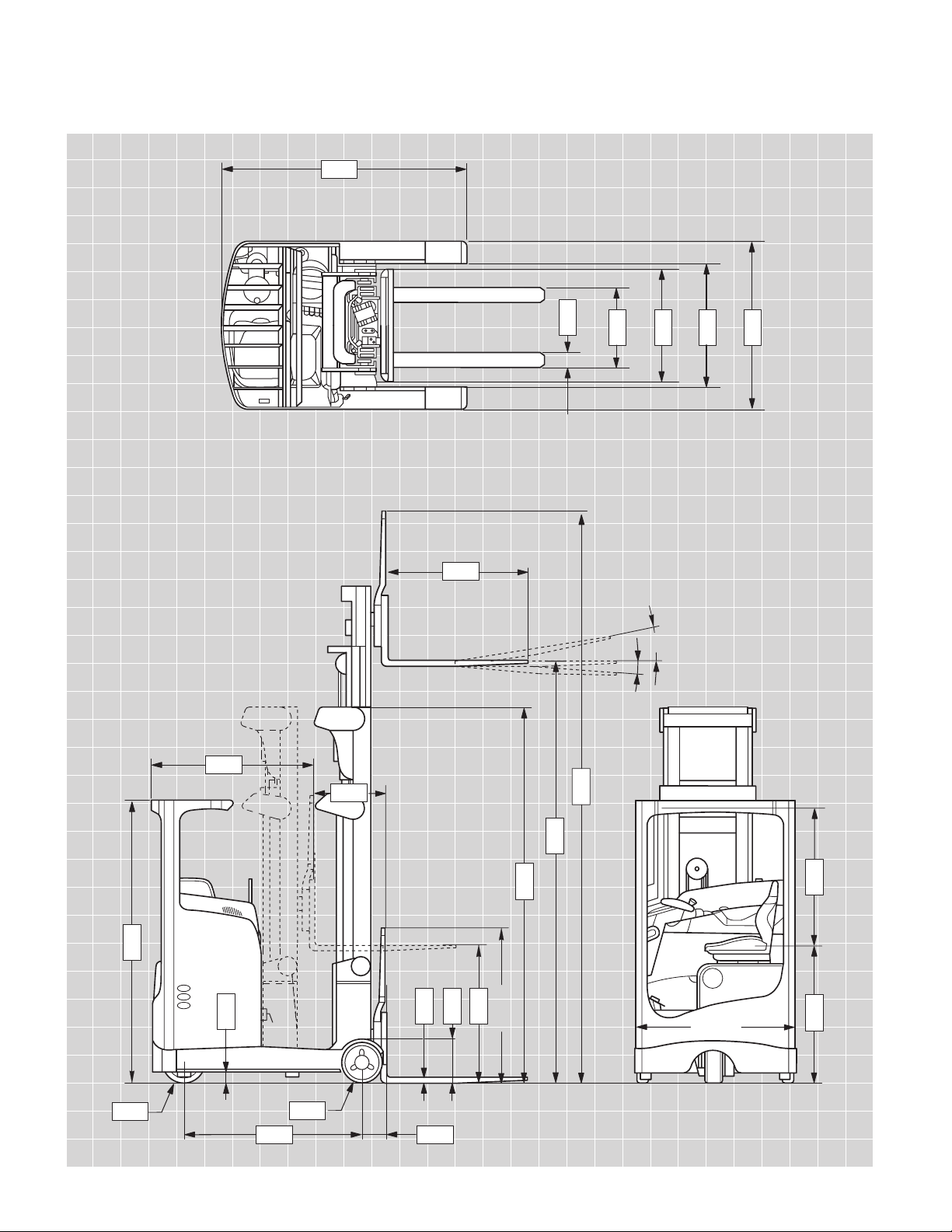
4.37
4.22
4.20
4.28
4.32
3.3
4.22
4.10
47.24"
4.3
4.2
4.4
4.5
2°
4°
4.21
1.8
49.80"
1.9
4.22
4.7
4.164.8
4.26
4.24
4.25
3.2
C
SR 5285H Series
Reach Truck
Page 3

SR 5285H Series
1.1 Manufacturer Crown Equipment Corporation
1.2 Model SR 5285H
1.3 Power Electric
1.4 Operator Type Rider / Seat
1.5 Load Capacity lb 4500
1.6 Load Center in 24
1.8 Load Distance Mast Extended in 8.54
General Information
1.9 Wheelbase in 58.07
2.1 Weight Less Battery lb 8110** (Option 1 Straddle)
3.1 Tire Type D / L in Vulkollan
3.2 Tires Front in 13.50 x 5.51
3.3 Tires Rear in 13.00 x 3.94
Tires
3.5 Wheels Number (x = driven) Front / Rear 1x / 2
4.1 Forkcarriage Tilt Forward / Backward º 2 / 4
4.2 Mast Collapsed Height in See Table 3
4.3 Free Lift* Load Backrest in See Table 3
4.4 Lift in See Table 3
4.5 Mast* (Extended Height) With Load Backrest in See Table 3
4.7 Overhead Guard Height in 84
4.8 Seat Height Compressed in 40.55
4.10 Outrigger Height in 13.62
4.15 Lowered Fork Height in 1.77
4.16 Head Room - Overhead Guard Not Compressed / Compressed in 39.49 / 40.20
4.20 Headlength in 58.03
4.21 Overall Width in See Table 1
4.22 Forks Standard H x W x L in 1.77 x 3.94 x 39.37
Dimensions
4.23 Fork Carriage ISO Class 2 A
4.24 Fork Carriage Width With Load Backrest in See Table 1
Fork Carriage Height in 45.67
Optional Fork Carriage Height in 31.50, 35.43, 39.37, 43.31, 47.24
4.25 Width Across Forks in See Table 1
4.26 Inside Straddle in See Table 1
4.28 Reach in 18.70
4.32 Ground Clearance Center Wheelbase in 2.99
4.37 Length over Outriggers in 74.92
5.1 Travel Speed With / Without Load mph 7.45 / 7.45
5.2 Lift Speed With / Without Load fpm 63 / 106
5.3 Lower Speed With / Without Load fpm 112 / 98
5.4 Reach Speed With / Without Load fpm 37 / 37
Performance
5.10 Service Brake Hydraulic
6.3 Max Battery Box Size in See Table 2
6.4 Battery Voltage Max Capacity 6h Rating V/Ah 48 / 1085
Battery
6.5 Battery Weight Minimum lb 2736
Optional Lengths in 42.01, 45.28, 48.03
Specifications
* With 47.24" Backrest
** With lift height 426"
Page 4

Table 1 - Straddle Options
Option 1 Option 2
4.21 Overall width in 56.10 62.01
4.24 Fork carriage width in 30.71 39.76
4.25 Width across forks, max in 29.52 38.58
4.26 Width inside straddle in 43.50 49.41
Sideshift movement in each direction in 2.75 3.94
Table 2 - Battery Size
6.3 Battery Size 46.97 x 30.56 x 19.64
L x H x W
* Remove standard spacer
*48.15 x 30.56 x 19.64
Table 3
SR 5285H Series
Specifications
4.4 4.2 4.3 4.5
Lift Height Overall Collapsed Height Free Lift** Overall Extended Height**
in in in in
360 145.4 99.8 406.10
378 151.3 105.7 423.81
391 155.6 110.0 436.81
426 167.4 121.8 472.24
450 175.3 129.7 495.87
** With 47.24" backrest
Page 5

SR 5285H Series
Technical Information
Capacity
Model SR 5285H: 4500 lb at
24" load center
Batteries/Electrical
System
The battery is pulled out of the
chassis with the reach carriage.
The battery can be removed
vertically or by rollers provided
allowing horizontal removal of
the battery from either side.
Standard Equipment
1. Crown Integrated Control
System with Access 1 2 3
2. Virtually maintenance free
three-phase (AC) motors
for traction, hydraulics
and steering
3. Motor controllers for traction, hydraulics and steering
4. CAN-Bus technology
5. Speed-sensitive electric
steering with programmable
turning ratios
6. Tilting steer column
7. Proportional fingertip control
for all hydraulic functions incorporating soft-lift/soft-stop
for smooth load movement
8. Information display:
• Access 1 2 3 on-board
diagnostics with real
time troubleshooting
capabilities
• Two-line LCD display with
16 characters per line
• Hour meters for
monitoring various truck
operating components
• Travel direction indicator
• Input for operator PIN
• Real-time clock and date
• Three selectable
performance profiles
• Battery discharge
indicator with lift lockout
• Steer wheel position
indicator
9. Integrated lift height and
load weight indicator with
truck performance linked
to fork height
10. Rack Height Select with
automatic laden/unladen
fork positioning starting
19.7" above secondary
mast staging
11. Tilt position assist
12. Free lift indicator, warning of
fork heights above free lift.
Can be programmed to
reduce top travel speed.
®
13. Thumb-operated travel
direction switch
14. Automotive type accelerator
and brake pedal
15. All-wheel braking
16. Braking systems:
• Parking brake
• Mechanical service brake
• Regenerative direction
reversal
• Regenerative coast
braking
17. Electric switch for parking
brake activation
18. Truck-Hold automatic
braking for slopes or
pushback racking
19. Electric power disconnect
switch
20. Vulkollan load wheels and
drive tire
21. Four easy-access storage
compartments
22. Comfortable knee and
hip padding within the
driver’s compartment
23. Comfortable suspension
seat with multiple
adjustment possibilities
24. Unique offset, wide
visibility mast
25. Clear view overhead guard
and load backrest
26. Lift slowdown prior to
reaching full mast extension
27. Reach-out battery system
28. Reach carriage slowdown
prior to reaching full extend
or retract position
29. Integrated sideshift with
tilting fork carriage
30. ISO Class 2A Forks
31. Battery plug SB 350
32. Battery rollers for horizontal
battery extraction
33. Strobe light
Optional Equipment
1. Lift cutout with/without
override switch
2. Mast mounted camera with
color or B&W monitor
3. Work lights 12-volt
4. Audible travel alarm
5. Dual-axis controls
6. Heated seat
7. Cloth seat
8. OHG covers
9. Work Assist™ Accessories
• Accessory pad clip
and hook
• Accessory clamp
• Accessory RF
mounting plate
• Accessory RF
mounting bracket
• Accessory clip pad
• Accessory hook
• Accessory pocket
• Accessory tube
10. Cold storage conditioning
for applications to -30° C
11. English/French/Spanish
labels
Driver’s Compartment
and Controls
A comfortable step height,
well-positioned grab handle and
non-slip floor mat ensure safe
and comfortable footing during
entry and exit.
Once seated, the operator has
the ability to tailor the compartment to “fit”. A high quality
comfortable seat can be
adjusted for the operator’s
weight. In addition, the seat can
be adjusted laterally, as well as
for the angle of the seatpad and
backrest. These adjustments,
coupled with a tilting steer
column, ensure a comfortable
position for any operator.
The left foot rests on the
operator “presence” pedal.
The right foot operates an
automotive style accelerator and
brake pedal arrangement, while
the right leg is supported by
ergonomically positioned
padding for the knee and hip
areas. The direction switch is
actuated with the right thumb
leaving the fingers of the right
hand free to operate all the
hydraulic controls. The fingertip
control levers allow for easy
blending of hydraulic functions
and are easily understood by
new or inexperienced operators.
There are four easily accessible
storage compartments. The
ergonomically formed armrest
is well padded and is designed
particularly with wrist support
in mind.
The display contains information
on the truck’s operating status,
a battery discharge indicator, a
travel direction indicator, steer
wheel position indicator, hour
meters for various truck operations, performance profile selection, and service information
for planned maintenance scheduling, fault finding and testing.
Coupled with a traditional
keyswitch, the information
display also serves as the PIN
input for those choosing to
employ the on-board user code
system thereby preventing
unauthorized use. The two-line
LCD display with 16 characters
per line is well illuminated for
excellent visibility. These standard features are complimented
by information such as fork
height and load weight indicators
should these options be chosen.
A further panel is integrated into
the chassis column and incorporates optional accessories such
as light switches.
Access 1 2 3
Integrated Control System
Crown’s Integrated Control
System provides unmatched
truck control for all primary
truck systems:
• Traction motor control
• Hydraulic valve and
motor control
• Steer motor control
• Braking
• Information/diagnostic display
Dedicated motor controllers are
employed to simplify troubleshooting and minimize replacement cost. All systems are linked
through CAN-Bus, which greatly
simplifies wiring while improving
diagnostic communication.
On ramps, or when interfacing
with push back racking, the
selectable Truck-Hold feature
electronically brakes the truck
when the accelerator is
released. The operator does
not have to apply the brake,
improving comfort and control
in these applications.
Selected travel speed remains
constant regardless of surfaces,
load weight or grades. The travel
speed, acceleration, and electric
braking ratio can be set via the
display, facilitating the best
possible productivity and energy
consumption for each application. Regenerative motor braking
helps save energy.
The control system for the
hydraulic pump motor and all
proportional hydraulics facilitates
precise and sensitive execution
of all hydraulic functions. All
hydraulic parameters such as lift,
lower, tilt, sideshift and reach
speeds are fully adjustable and
can therefore be adapted to
different applications.
®
Page 6

SR 5285H Series
Technical Information
Access 1 2 3
Integrated Control System
(continued)
Crown’s Access 1 2 3 Diagnostics is the most comprehensive
fault detection system in the
industry. A properly trained
technician can actively view
inputs and outputs during truck
operation thereby significantly
reducing search and downtime.
The information display is the
first point for troubleshooting.
All operator information such as
travel and hydraulic parameters,
truck monitors, etc. can be
obtained and adjusted via the
display. No handset or laptop
is required – all functions are
onboard and easy to use.
Performance Profiling
Three pre-set performance
profiles can be selected on the
display. The pre-set parameters
can be changed to a multitude
of other traction and hydraulic
parameters allowing adaptation
to each customer’s requirements.
Hydraulic System
Proportional control ensures all
hydraulic functions can be individually and precisely actuated
regardless of load. Four hydraulic
functions (lift/lower, tilt, sideshift,
reach) are standard. All hydraulic
hoses are internally reeved
through the mast.
The utilization of an internal
gear pump reduces the noise
level and ensures high efficiency
in all applications. The hydraulic
oil is filtered twice. The return
and suction filters can be
exchanged without draining
the hydraulic tank.
Mast and Reach Carriage
Crown’s unique offset, wide view
mast delivers excellent visibility at
height as well as for low-level
operations. Mast cross-bracing
and overhead guard bracing
have been angled and hose and
chain rollers have been canted to
further enhance visibility. A load
backrest designed for maximum
visibility is also standard. The
standard three-stage full-free lift
mast incorporates integrated
sideshift with tilting carriage,
hence reducing head length.
Mast channels are reinforced
to minimize static and
dynamic deflection.
Spring dampers are located on
the fork carriage to reduce noise
while staging and the lifting
speed is slowed before reaching
the lift limit. Elastomer dampers
between the mast stages and
hydraulic dampening in the
free-lift cylinder reduce noise
while lowering.
The anti-friction mast rollers are
canted to reduce energy consumption and ensure longer life.
The heavy-duty reach carriage
moves on four main roller
bearings. Two adjustable
backing rollers minimize
dynamic mast rocking while
four adjustable side rollers
ensure very smooth movement
and precise positioning.
Drive Unit
A highly efficient drive unit with
helical gears, integrated pinion
and vertically mounted threephase (AC) traction motor
provides quiet, powerful traction
performance. A large Vulkollan
drive wheel (13.50" x 5.51")
offers high load capacity, long
life and excellent travel comfort.
Steering
The electric steering system
is travel speed sensitive. It
provides fast direct response
with light effort for controlled
maneuverability. Variable steering
ratio can be programmed to suit
specific needs. A fail-safe control
circuit applies motor braking and
parking brake if a fault is detected.
Brakes
The foot pedal applies the
service brake. The brake pressure is distributed to the load
wheels and the drive wheel by a
master cylinder in combination
with regenerative motor braking.
This ensures the truck brakes
smoothly and efficiently.
The parking brake is activated by
a switch in the operator compartment. The spring-applied / electro-magnetically released brake
is applied on the drive wheel. The
parking brake is automatically
applied when the operator exits
the truck.
The truck can also be brought to
a stop by reversing the travel
direction using the electric
regenerative plugging function.
Furthermore, the truck is
equipped with an electric autobrake function, which stops the
truck as the accelerator pedal is
released (controlled coasting).
Both electric braking functions
can be set via the display.
Motors
All motors are highly efficient
three-phase (AC) which provide
high available torque and seamless reversal. Traction and
hydraulic motors are oversized
for superior thermal capability
and are especially suitable for
high loads and high ambient
temperature applications.
Other Options
1. Audible travel alarm
2. Flashing lights
Safety considerations and
dangers associated with
audible travel alarms and
flashing lights include:
• Multiple alarms and/or lights
can cause confusion.
• Workers ignore the alarms
and/or lights after day-in and
day-out exposure.
• Operator may transfer the
responsibility for “looking out”
to the pedestrians.
• Annoys operators and
pedestrians.
Other Options Available
Contact your local Crown dealer.
Dimensions and performance
data given may vary due to
manufacturing tolerances.
Performance is based on an
average size vehicle and is
affected by weight, condition of
truck, how it is equipped and the
conditions of the operating area.
Crown products and specifications are subject to change
without notice.
C
Crown Equipment Corporation
New Bremen, Ohio 45869 USA
Tel 419-629-2311
Fax 419-629-3796
crown.com
Because Crown is continually improving its products,
specifications are subject to change without notice.
Crown, the Momentum symbol, Access 1 2 3
and Work Assist are trademarks of
Crown Equipment Corporation.
Copyright 2005 Crown Equipment Corporation
SF14484 6/05
Printed in U.S.A.
 Loading...