

Page 1
C
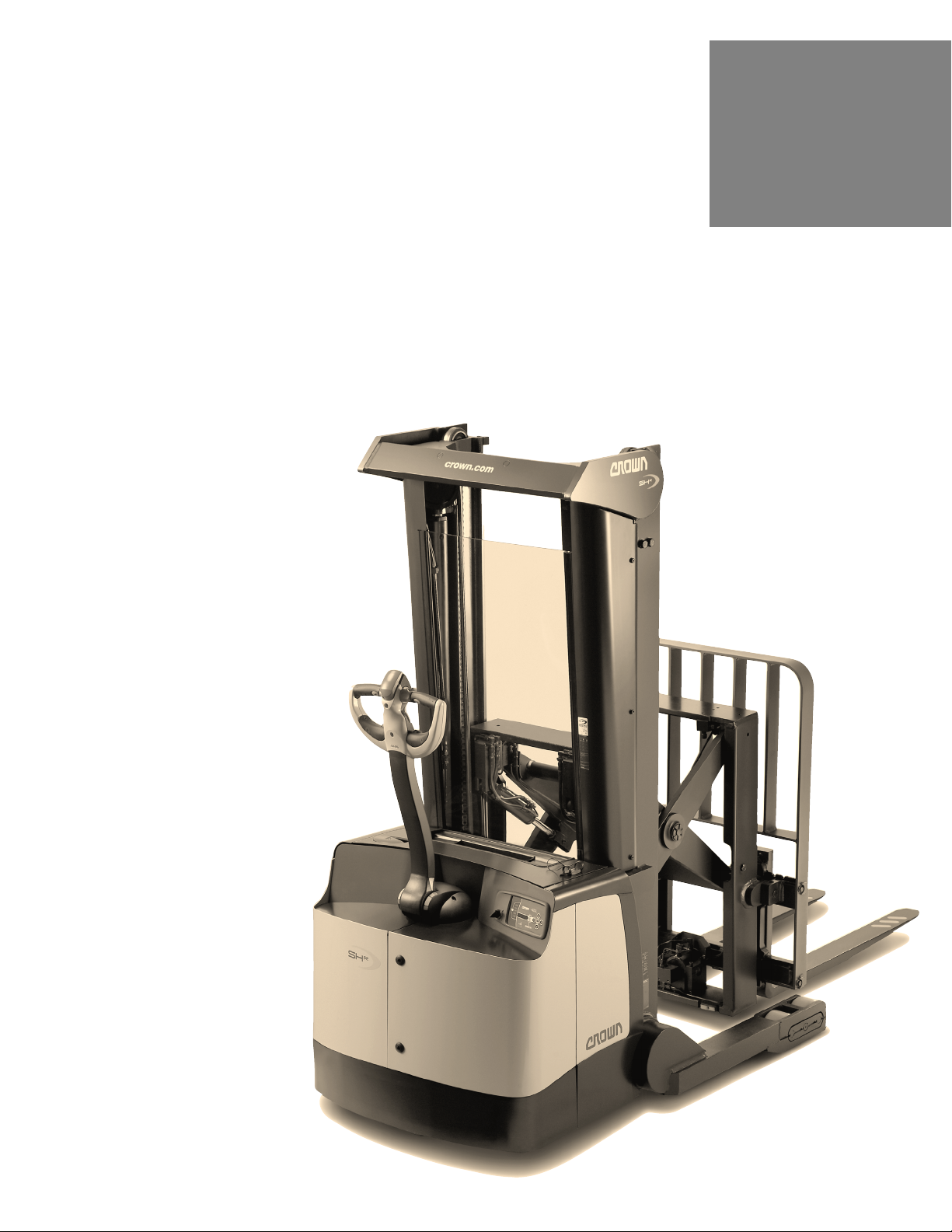
SHR 5500
Specifications
SHR 5500 Series
Heavy-Duty Walkie
Reach Stacker
Series
Page 2
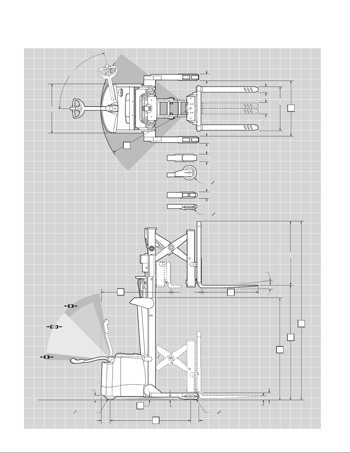
BRAKE
o 10" x 3"
80°
3°
3°
36"
4.13"
4"
8"
32"
16
4.13"
5.5"
4.13"
6.76" 5.73"
12
9
47"
17
23.2"
14
21
(1) o 10.5" x 4"
(2) o 4" x 2.88"
2"
(2) o 5" x 2.88"
3"
5"
13
11
3.5"
BRAKE
OVERRIDE
BRAKE
DRIVE
15
C
SHR 5500 Series
Heavy-Duty Walkie
Reach Stacker
Page 3

SHR 5500 Series
1 Manufacturer Crown Equipment Corporation
2 Model SHR 5520-25 SHR 5520-30 SHR 5540-35
3 Load Capacity lb See Chart See Chart See Chart
4 Load Center in 24 24 24
5 Power Electric 24 Volts 24 Volts 24 Volts
6 Operator Type Walkie Reach Stacker Reach Stacker Reach Stacker
General Information
7 Tire Type Load/Drive Poly/Vulkolan Poly/Vulkolan Poly/Vulkolan
8 Wheels (x=driven) Load/Drive 4/1x 4/1x 4/1x
9 Lifting Height in See Chart See Chart See Chart
13 Head Length* in 44 44 50.5
14 Wheelbase in 52.7 52.7 59.2
15 Turning Radius in 59.4 59.4 65.9
16 Inside Straddle in 34 - 50 inches in 2" increments
Dimensions
17 Forks Standard LxWxT in 36 x 4 x 1.5 36 x 4 x 1.5 36 x 4 x 1.75
Optional Lengths in 30, 39, 42, 45, 48, 54, 60
18 Travel Speeds Empty/Loaded mph 3.7 / 3.4
19 Lift Speeds Empty/Loaded fpm 48.4 / 29.5
20 Lowering Speeds Empty/Loaded fpm 50 / 50
21 Grade Clearance %998
22 Battery Min Weight/Max Amp 510 / 300 510 / 300 975 / 660
Performance
Max Battery Size WxLxH 6.62 x 34.37 x 24.8 6.62 x 34.37 x 24.8 13.12 x 31.10 x 24.8
Specifications
* Add 2.1" for Side Shift
Mast Type TL – Limited Free Lift TT – Triple Telescopic
9 Lifting Height in 127.5 150.5 156 192
3 Load Capacity SHR 5520-25 lb 2500 2500 2500 na
SHR 5520-30 lb 3000 3000 3000 na
SHR 5540-35 lb 3500 3500 3500 2500
10 Free Lift with LBR in 6 6 28 42
11 Collapsed Height in 83.5 95.5 75 89
12 Extended Height with LBR in 175 198 204 240
Mast and Weight
23 Min ID Straddle Width in 34 34 34 42
24 Truck Weight SHR 5520-25 lb 3585 3690 4130 na
w/o Battery**
** Add 105 lb for Side Shift
SHR 5520-30 lb 4100 4205 4650 na
SHR 5540-35 lb 4055 4160 4600 4735
Page 4

SHR 5500 Series
B
Right Angle Aisles
Pallet
Length
Pallet
Width
A
Equal Intersecting Aisles
Aisle Planning Guide
Capacity
Model SHR 5520-25: 2500 lb
at 24" load center
Model SHR 5520-30: 3000 lb
at 24" load center
Model SHR 5540-35: 3500 lb
at 24" load center
Maximum Battery Size
SHR 5520-25: 6.62" wide
x 34.37" long x 24.8" high –
up to 300 amp hours, 24 volts
SHR 5520-30: 6.62" wide
x 34.37" long x 24.8" high –
up to 300 amp hours, 24 volts
SHR 5540-35: 13.12" wide
x 31.10" long x 24.8" high –
up to 660 amp hours, 24 volts
Standard Equipment
1. 24-volt electrical system
2. Crown’s Access 1 2 3
®
Comprehensive
System Control
3. Access 1 2 3 display
• Eight-character scrolling
display, 5 button access
• Three selectable
performance levels
• BDI with lift interrrupt
• Five hour meters
• Event codes
• Access 1 2 3
diagnostics with real
time troubleshooting
• PIN code capability
4.
AC traction and steer motors
5. Performance enhancing
features
• X10®Handle
• Brake override
• Electronic power steering
• Ramp hold and
speed control
• Power boost
• High-visibility mast
and carriage
• Low profile power unit
• Tool storage tray
6. Wire mesh guard - mast
7. Volkollan drive tire –
10" dia. x 3" wide
8. Polyurethane load wheels –
5" dia. x 2.88" wide
9. InfoPoint®System
10. Steel power unit covers
11. 47" tall load backrest
12. Emergency power
disconnect
13. Key switch
14. Horn
15. SB175 gray
battery connector
16. Reversing button
17. Electric park brake
18. Fork tip indicators
19. Battery compartment
rollers
SHR 5520
Pallet 30 36 40 42 48
Width
36 in 62 78 62 81 62 85 62 89 62 97
40 in 64 78 64 82 64 87 64 90 64 97
42 in 65 78 65 81 65 88 65 90 66 97
48 in 68 80 68 83 68 87 68 91 69 99
SHR 5540
Pallet 30 36 40 42 48
Width
36 in 65 83 65 86 66 92 66 95 66 102
40 in 68 84 68 87 68 92 68 95 68 102
42 in 68 84 68 86 68 93 68 95 69 103
48 in 72 85 72 87 72 93 72 96 72 104
A = Equal Intersecting Aisles
B = Right Angle Aisles
Add 2.5" if side shift option is used.
Add 6" to 12" to all aisle dimensions for maximum maneuverability.
ABABAB AB AB
ABABAB AB AB
SHR 5500 Series
Optional Equipment
1. 30 amp on-board charger
(6.62" battery box)
2. Keyless on-off switch
3. Work Assist™ Accessories:
• Clip pad
• Hook
• Clip pad and hook
• Pocket
• Fan
4. Sideshift with internal hosing
5. Optional fork lengths (30",
39", 42", 45", 48", 54", 60")
6. Freezer conditioning
(Continuous -30° C / -22° F)
7. Plexiglass safety shield
8. 10" dia. x 4" wide drive tire
• Soft poly
• Siped soft poly
9. Polyurethane load wheels
• 4" dia. x 2.88" wide
• 10.5" dia. x 4" wide
10. InfoLink® ready
11. SBE 160 battery connector
Pallet Length
Pallet Length
Technical Information
Operator Controls
Crown’s robust X10 handle
places all control buttons in the
optimum position for ease of
operation with either hand and
to minimize hand and wrist
movements. An ergonomic
forward/reverse thumb wheel
allows for precise maneuvering.
The control hand grips are
urethane covered for insulation
from cold and vibration with
integrated horn buttons for easy
activation. The handle contains a
safety button which reverses the
direction of the truck should the
button touch the operator.
The physical efforts to hold the
handle at a comfortable height
was minimized to reduce fatigue.
A rabbit/turtle switch incorporates two levels of programmable
travel performance so operators
can select the setting that
matches their experience level
or application requirements.
Exclusive brake override feature
allows slow speed travel with
the handle near vertical. This
feature improves maneuverability
in tight areas.
Page 5

SHR 5500 Series
Technical Information
Performance
The SHR 5500 Series incorporates the latest generation AC
drive system enhanced with
Access 1 2 3 technology.
Crown’s Access 1 2 3 technology
continuously monitors truck
systems and adjusts system
parameters to deliver optimum
performance and control. The
Access Display provides a
convenient interface for operators
keeping them informed of any
changes impacting truck performance and allowing them to
choose from three performance
profiles when enabled.
Programmable performance
settings enable authorized
personnel to tune the lift truck
to different operator skill levels,
or to meet specific application
requirements. In addition,
up to 25 PIN codes can be
assigned to individual operators
and matched to one of the
pre-programmed performance
profiles if desired.
Electronic power steering allows
the operator to maneuver heavy
loads in tight spaces throughout
the day while minimizing fatigue.
Smooth travel and lift performance combine with excellent
controls provided by the X10
handle to increase productivity.
The SHR 5500 Series features
ramp hold and speed control
to improve operation on small
inclines or ramps. The ramp hold
feature uses the motor to prevent
truck movement when the brake
is released and no travel command is present. The ramp speed
control feature insures that actual
travel speed matches requested
travel speed. If the truck encounters an obstacle, a power boost
feature delivers up to 15 percent
more power than normally available for a full three seconds to
overcome the obstruction.
Electrical System
A heavy-duty 24-volt fused
electrical system utilizes
microprocessor controls for
maximum energy efficiency,
reduced maintenance and infinite
speed control capability.
Access control modules for
travel, lift and steer are sealed
from dirt, dust and moisture
for trouble-free operation. All
contactors have been eliminated
except for the main line contactor.
A 175 amp battery connector with
disconnect handle is standard.
Hydraulic System
Heavy-duty hydraulic motor
(4.8 kw) is transistor controlled
and matched with a gear type
pump selected for optimum lift
performance and low noise.
Single-speed lift with programmable acceleration - deceleration
and programmable two-speed
lowering enables customization
to match operator preference or
application requirements.
Cylinder rods are hard-plated
chrome with polyurethane seals.
Relief valve tuned to capacity
protects all components in the
hydraulic system. Reservoir
incorporates an in-tank 10
micron return filter for removing
debris from oil.
Drive Unit / Brake
Heavy-duty gearbox with
helical spur input gear for quiet
operation.
Regenerative motor braking
is activated under a downhill
condition, during plugging or
when the directional control is
returned to neutral. An electromagnetic brake, spring applied
and electrically released, is
mounted on top of the drive
motor. The electro-magnetic
brake serves as the parking
brake and applies when the
control handle position moves
from the operating zone to brake
zone during truck operation.
Power Steering
Electronic power steering is provided by a heavy-duty AC motor
that pivots the drive unit when
steer tiller movement is detected.
Mast
High visibility two and three-stage
mast design with angled cross
bracing and lift cylinders located
behind nested I-beams provides
maximum visibility for load
positioning and placement.
Crown’s staging cushions
coupled with lowering dampers
ensure smooth operation.
Rolled steel outer mast channels
and inner I-beams roll on canted,
steel, anti-friction roller bearings
for minimal current draw and long
life. Mast and chain rollers are
sealed and lubricated for life.
Telescoping mast sections nest
to reduce truck length. Heavier
mast cross bracing design
increases stiffness.
Reach Mechanism
An exclusive reach mechanism
design provides unmatched
visibility at all rack levels.
Serviceability / Durability
The Access display simplifies
service for technicians by
providing advanced diagnostics
without the need for separate
handsets. The display allows the
technician to view event service
codes and truck hours when
event occurred, perform system
calibrations or functional tests of
components, and make necessary adjustments. Crown’s
InfoPoint System compliments
Access 1 2 3 diagnostics by
providing a Quick Reference
Guide, on-truck component
maps and information nuggets to
further simplify troubleshooting.
All wiring is color coded.
Removable steel power unit
doors are hinged for ease of
opening providing excellent
accessibility to the distribution
panel and all other components.
Steel covers provide added
protection to critical internal
components.
Removable steel battery covers
and hinged cover allow easy
access to the battery. Battery
removal can be accomplished
from either side. Battery compartment rollers are standard.
The X10 handle incorporates a
vacuum die cast process using
high-grade aluminum and benefits
from structural webbing for maximum strength and durability.
Other Options
1. Amber strobe light
2. Travel alarm: reverse, forward
or both
Safety considerations and
dangers associated with audible
travel alarms and strobe lights
include:
• Multiple alarms and/or lights
can cause confusion.
• Workers ignore the alarms
and/or lights after day-in and
day-out exposure.
• Operator may transfer the
responsibility for “looking out”
to the pedestrians.
• Annoys operators and
pedestrians.
Dimensions and performance
data given may vary due to
manufacturing tolerances.
Performance is based on an
average size vehicle and is
affected by weight, condition of
truck, how it is equipped and the
conditions of the operating area.
Crown products and specifications are subject to change
without notice.
Page 6

C
Crown Equipment Corporation
New Bremen, Ohio 45869 USA
Tel 419-629-2311
Fax 419-629-3796
crown.com
You can count on Crown to build lift trucks
designed for safe operation, but that’s
only part of the safety equation. Crown
encourages safe operating practices through
ongoing operator training, safety-focused
supervision, maintenance and a safe working
environment. Go to crown.com and view our
safety section to learn more.
Because Crown is continually improving its products,
specifications are subject to change without notice.
Crown, the Crown logo, the color beige, the Momentum
symbol, Access 1 2 3, InfoPoint, InfoLink and X10 Handle
are trademarks of Crown Equipment Corporation.
Copyright 2008 Crown Equipment Corporation
SF14906 1/08
Printed in U.S.A.
 Loading...