

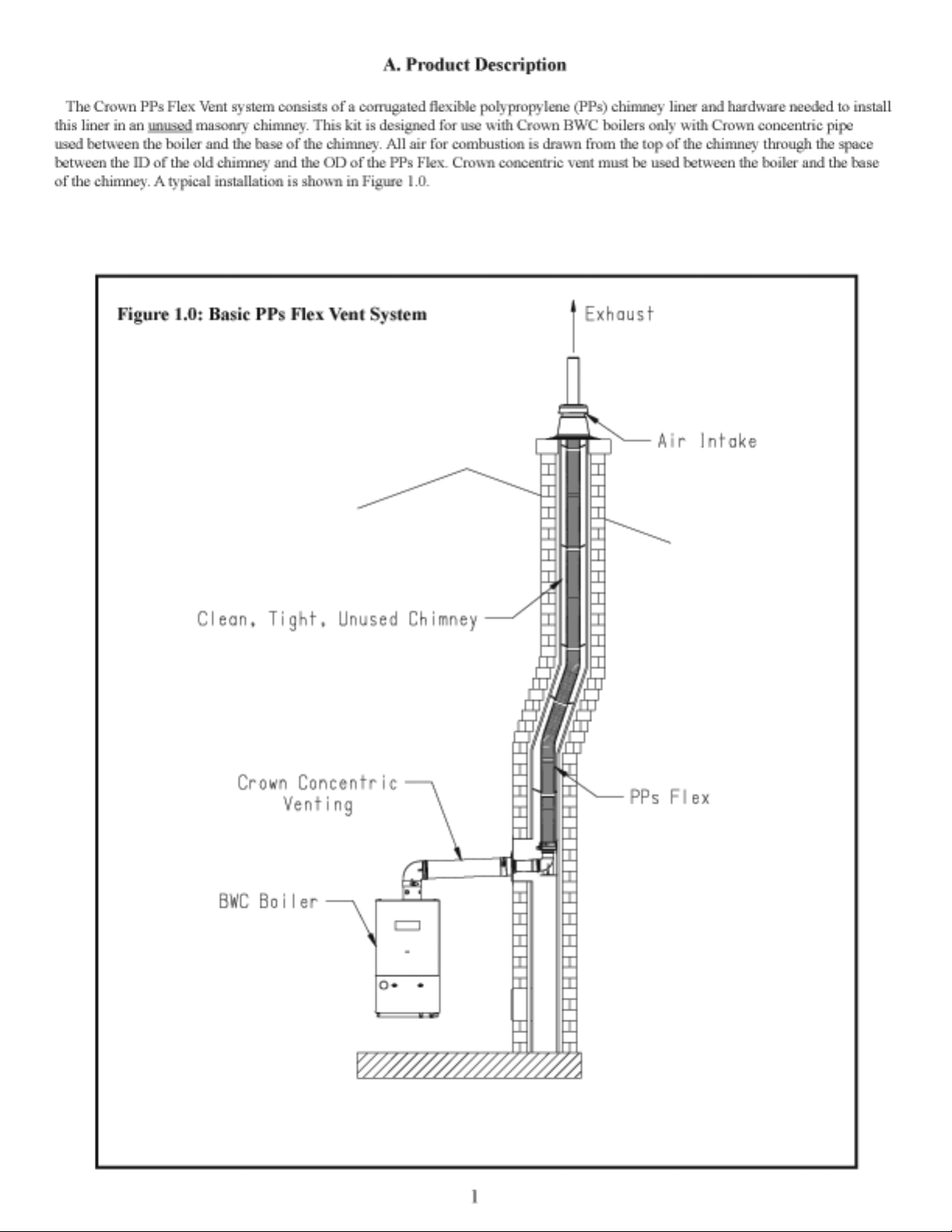
Page 1

Page 2

Page 3
Page 4
Page 5
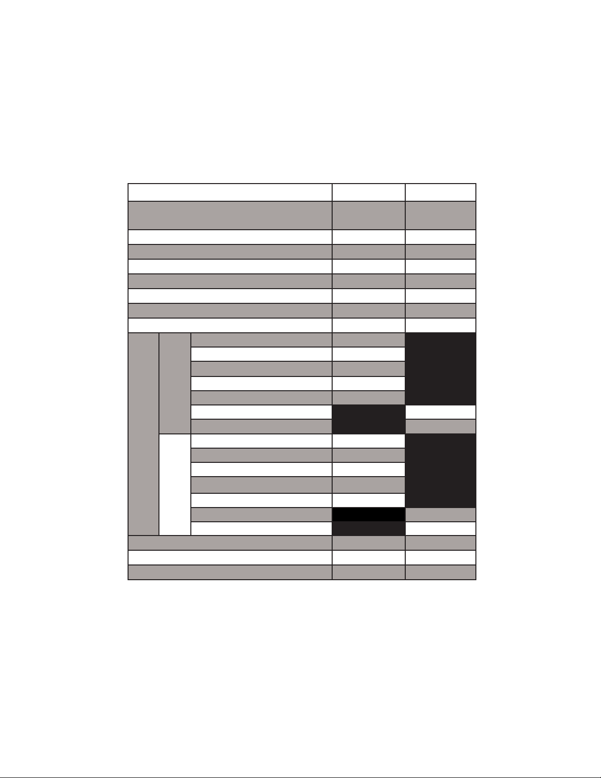
Table 1.1: Summary of PPs Flex Venting Options
VENT OPTION # 9 10
CLASSIFICATION USED IN THIS MANUAL
ILLUSTRATED IN FIGURE 1.0 1.0
VENT PIPE PENETRATION THROUGH STRUCTURE CHIMNEY CAP CHIMNEY CAP
AIR INTAKE PENETRATION THROUGH STRUCTURE CHIMNEY CAP CHIMNEY CAP
MIN CHASE ID (ROUND)
MIN CHASE ID (RECTANGULAR)
NOMINAL PPs FLEX LINER SIZE
CONCENTRIC VENT/INTAKE CONNECTOR SIZE
BWC070 51ft
BWC090 51ft
BWC120 51ft
BWC151 51ft
VENT
BWC150 47ft
BWC225 45ft
BWC300 68ft
BWC070 51ft
BWC090 51ft
BWC120 51ft
BWC151 51ft
INLET
(INLUDING PPS FLEX IN CHASE)
MAXIMUM TOTAL VENT LENGTH
MAX CHASE HEIGHT
CROWN PPs FLEX LINER PART # (32ft COIL) 230955 230956
CROWN PPs FLEX INSTALLATION KIT PART # 230958 230959
BWC150 47ft
BWC225 45ft
BWC300 68ft
PPs FLEX
(MASONRY)
6” DIA 7” DIA
6” x 6” 7” x 7”
80 mm 100mm
80/125 100/150
32ft 32ft
PPs FLEX
(MASONRY)
3
Page 6

WARNING
Failure to ensure that the chimney is clean, leak tight, water tight, and structurally sound could result in severe
corrosion damage to the boiler, damage to the vent system, restriction of combustion air supply, or the entry of flue
products into the structure which in turn could cause unreliable operation, property damage, personal injury, or loss of
life.
Installation of this kit will require an opening at the base of the chimney (at the level of the horizontal vent connection) that is 4)
approximately 7” wide and 12” tall. A slightly smaller, or significantly larger opening may be required depending on the chimney
wall thickness. Before attempting to install this kit, make sure that such an opening either exists, or can be made, without
compromising the structural integrity of the chimney (much of this opening will be re-closed later in the installation process).
Maximum distance from center of chimney chase to outside surface of chimney base is 23” (Figure 1.2).5)
Verify that there are no offsets in the chimney that will cause the PPs Flex Liner to bend more than 45 degrees. 6)
Verify that it will be possible to maintain a 5/8in per ft. pitch towards the boiler in all horizontal piping between the boiler and the 7)
elbow at the base of the chimney chase.
PPs Flex Liner and the hardware needed for a single PPs Flex Liner installation are sold separately. All hardware is included in a 8)
“PPs Flex Installation kit”. Table 1.1 shows the Crown part numbers for these kits and the PPs Flex Liner itself.
4
Page 7

Page 8

Page 9

Page 10

Page 11

Page 12

Remove the rope or pull tool from the end of the vent. 6)
Verify that the Male Adaptor is undamaged. Lubricate the brown gasket in the female end of the Elbow with a few drops of water 7)
and insert the Male Adaptor fully into the Elbow.
Mount the bottom end of the PPs Flex Liner with the Elbow onto the Elbow Support Bracket installed in Step #2 using the Male 8)
Adapter Clamp as shown in Figure 1.9.
The cap provided with this kit is designed for installation over chimney crowns with round openings up to 12” and square 9)
openings having inside dimensions up to 8-1/2”. If the opening in the crown is larger than this, the installer must provide a
weather tight crown with an opening below these limits. The minimum diameter of the opening in this crown must be 6” for the
80mm PPs Flex Liner and 7” for 100mm PPs Flex Liner. Make such modifications to the crown in accordance with standard
practice before proceeding further.
Cut the top end of the PPs Flex Liner so that it protrudes between 1-3/4” and 2-1/4” above the top surface of the crown (Figure 10)
2.0). Cut the pipe in one of the grooves using a sharp utility knife.
Install the Female Adaptor on the top end of the PPs Flex Liner using the same technique used to attach the Male Adaptor (Figure 11)
1.7). Allow the Female Adaptor to rest on Support Cross.
Apply a bead of weather resistant caulk or mortar to the crown and set the Lower Vent Cap flange on the crown so that the joint 12)
between the Lower Vent Cap flange and the crown is completely air and water tight. Anchor the Lower Vent Cap Flange to the
crown using an appropriate fastener through the knock-out in each corner.
Moisten the brown gasket in top of the Female Adaptor with a small amount of water and fully insert the Stainless Termination 13)
Pipe.
Slide the Upper Vent Cap over the Stainless Termination Pipe and snap in place on the Lower Cap. 14)
Provide a thimble for the penetration into the bottom of the chimney chase. This can be a section of smoke pipe, duct or ceramic 15)
chimney tile. It must be installed so that the following requirements are met (Figure 2.1):
The inside dimensions of this thimble must meet the minimum chase ID requirements shown in Table 1.1.•
The thimble must be located so that a 5/8” in per ft. pitch can be maintained in the Vent Stub between the Elbow and •
Concentric Adaptor.
The thimble must be sealed to both the chimney flue and the exterior surface of the chimney using mortar or other suitable •
sealant having a service temperature rating of at least 210F.
The thimble must not protrude into the original chimney flue.•
Lubricate the gasket in the female end of the Vent Stub with a few drops of water and push it onto the Elbow. 16)
Mount the Exterior Wall Plate so that the Vent Stub will pass through the center of the opening in this plate when properly 17)
pitched. Anchor the Exterior Wall Plate to the wall using four masonry anchors, or other appropriate fasteners, capable of
supporting at least 40lbs each. Note: Exterior Wall plate must completely cover the thimble. Exterior Wall Plate can be cut down
as long as this condition is met. If the flange on the Concentric Adaptor is large enough to cover the thimble, the exterior wall
plate may be omitted completely. If the Exterior Wall Plate is too small to cover the thimble, a larger plate may be fabricated in
the field using 18GA (or heavier) galvanized steel. If the exterior wall plate is cut down or replaced, the Usage Warning Label on
the plate must be saved and attached to the base of the chimney near the concentric adaptor.
Seal the Exterior Wall Plate (if used) to the outer wall of the chimney using a suitable sealant having a service temperature rating 18)
of at least 210F.
Mark the Vent stub at a point 1” beyond where it exits the Exterior Wall Plate (Figure 2.1). Cut the Vent Stub squarely at this point 19)
with a fine tooth hacksaw or PVC saw. De-burr the cut end with a file, razor blade, or fine sandpaper.
10
Page 13

Page 14

Lubricate the gasket in the female side of the Concentric Adaptor with a few drops of water. Apply a bead of sealant to the 20)
Concentric Adaptor flange and secure to the Exterior Wall Plate using the four #6 stainless steel sheet metal screws provided. If
the Exterior Wall Plate is omitted as described in Step 17, secure the Concentric Adaptor directly to the exterior wall using four
masonry anchors, or other appropriate fasteners, capable of supporting at least 40lbs each.
If there is a cleanout at the base of the chimney, seal it. 21)
Assemble the concentric vent system between the boiler and the base of the chimney in accordance with the instructions in the 22)
appropriate BWC installation manual.
C. PPs Flex Maintenance
In addition to the maintenance steps described in the boiler installation manual, the use of the PPs Flex Liner system requires that
the following steps be performed by a service technician as part of the annual maintenance procedure:
Disconnect the concentric venting from the Concentric Vent Adaptor at the base of the chimney. Use a flashlight and mirror to 1)
inspect as much of the chase and PPs vent system as possible through the openings in this adaptor. Look for:
Loose mortar or other debris in the chase (old chimney). If any is found, clean it out. •
Damage or deterioration to visible portions of the PPs Flex system itself.•
Obstructions inside the PPs Flex system itself•
Visually inspect all exposed portions of the chimney inside and outside of the building that can be accessed without the use of 2)
ladders. Look for:
Deterioration of the masonry chimney including possible leaks at mortar joints.•
Damage, deterioration, or blockage of the Cap assembly•
Signs that water may be entering the chase•
If the above inspections suggest that further action is needed in order to assure that the chimney chase is still in compliance with 3)
Part B of this manual, perform additional inspections and repairs as necessary.
Reassemble the concentric vent system between the base of the chimney and the boiler. Verify that it is properly supported.4)
Inspect the Exterior Wall plate and Concentric Adaptor to be sure that they are firmly attached to the base of the chimney and are 5)
sealed.
Warning
Failure to maintain the vent system, and boiler in accordance with these maintenance instructions, and those in the
boiler installation and operating manual could cause unreliable operation, severe property damage, personal injury,
or loss of life.
Important
Failure to document the annual boiler and vent system maintenance described above may void the boiler warranty.
12
Page 15

Page 16

Manufacturer of Hydronic Heating Products
P.O. Box 14818 3633 I. Street
Philadelphia, PA 19134
Tel: (215) 535-8900 • Fax: (215) 535-9736 • www.crownboiler.com
PN: 980079 Rev. 0
07/10
 Loading...