

Page 1
(
)
MB-100
”
MB-200
MB SYSTEM
ELECTRONICS INTERFACE
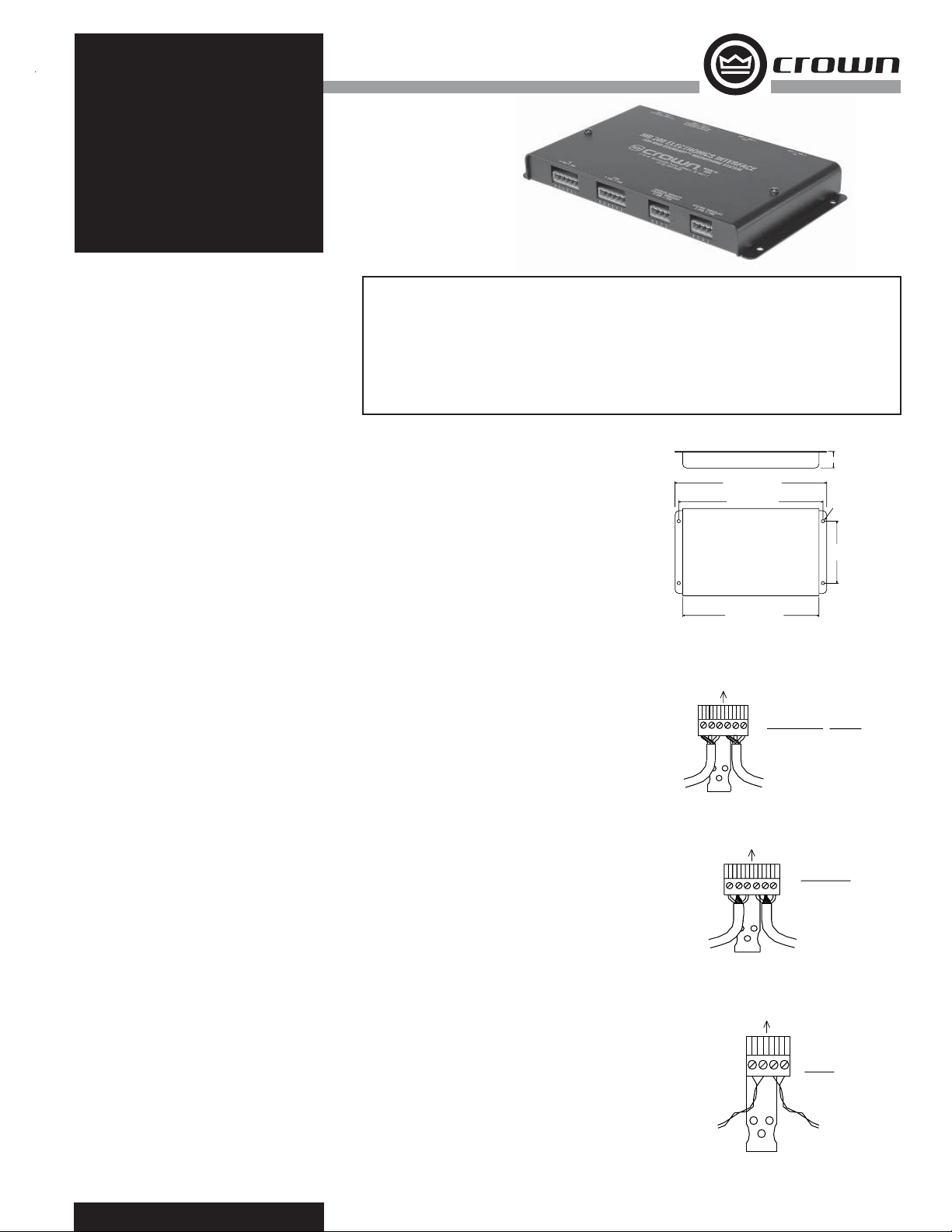
he MB-100 is an electronics interface that powers
up to four Crown
or MB-4/E microphones. This interface for four mics
T
®
mini-boundary™ MB-1, MB-2,
reduces the size and cost of the microphone system and
reduces installation time.
The MB-100 provides programmable switching to turn
the mic on or off if desired (switches not provided). The
MB-200 interface also has remote switch sensing via an
optical coupler.
Two microphones can be wired to each pluggable terminal
block, which plugs into the MB-100 or MB-200 interface.
Pluggable terminal blocks are also provided for the balanced outputs on the interface, and for remote switch
sensing.
The interface is powered by 18 to 48V phantom power
from a mixer or a phantom power supply.
Wiring Interface Mic Inputs
Before installing the mics, wire them to the included pluggable terminal blocks (PTBs) as described below:
1. For the MB-1 and MB-2 mics, solder the proper length
of cable to each mic jack as follows:
Sleeve (common ground) to cable shield
Tip (audio) to cable (+) lead
Ring (LED) to cable (–) lead
2. Wire the cables for two adjacent mics to the PTB as
shown in Fig. 2.
If you do NOT want the LEDs to light, disconnect the leads
from PTB terminals 2 and 5.
3. Similarly, wire MICS 3 and 4 (if used) to another
6-prong PTB.
Wiring Interface Outputs
Please refer to Fig. 3. Repeat this wiring for another interface output (if used).
Wiring Mic On/Off Switches
As supplied from the factory, the mics are always on. For
optional user control of each microphone, you can use
either a momentary or a push-on/push-off SPST switch
(not supplied). Proceed as described below:
1. Two switches connect to one pluggable terminal block
(PTB). Run a twisted pair from each switch to a 4-prong
PTB, and connect as described below (Fig. 4). Wire polarity
does not matter.
Switch for mic 1 to PTB terminals 1 and 2
Switch for mic 2 to PTB terminals 3 and 4
2. Similarly, wire switches for mics 3 and 4 (if used) to
another PTB.
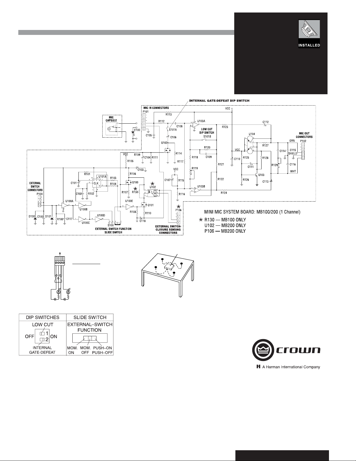
Wiring for External Switch-Closure Sensing (MB-200
only)
If external switch-closure sensing is desired, wire two
sensing circuits to one PTB as shown in Fig. 5. Repeat this
wiring for another pair of mics (if used).
Setting Internal Switch, Gating, and EQ Controls
Remove the MB-100 interface cover. Locate the four slide
switches, one for each mic (see Fig. 6). Set each switch to
one of these modes:
Push-on/push-off
Momentary on (press-to-talk)
Momentary off (mute or privacy button)
Set the low-cut and internal-gate defeat as desired for
each mic. Low-cut is –7 dB at 100 Hz.
Features
• Interfaces Crown MB-1, MB-2, or MB-4/E
microphones to a mixer with phantom power
• Interface powers up to four mics via phantom
power from mixer and provides four balanced
low-impedance outputs
Specifi cations
For microphone specs, see the individual data sheets for
the MB-1, MB-2 and MB-4/E.
Output impedance: 150 ohms, balanced (recommended
load impedance 1000 ohms or greater).
Polarity: Positive (inward) pressure on diaphragm produc-
es positive voltage on output terminal 1 with respect to
terminal 3, and on terminal 4 with respect to terminal 6.
Operating voltage: Phantom power, 18 to 48V DC on
output terminals 1 and 3 with respect to terminal 2, and
on terminals 4 and 6 with respect to terminal 5.
Operating temperature range: –10° to +50° C, or +14°
to +122° F.
Current drain: 5 mA nominal per mic.
Cable connectors (supplied with MB-100 or MB-200
interface):
• Pluggable terminal block (PTB) for connecting two microphones to two mic inputs on the interface. Two of these
PTBs are supplied, for use with up to four mics.
• PTB for connecting two mic-level outputs to two mixer
mic inputs. Two of these PTBs are supplied, for use with
up to four mics.
• PTB for connecting two mic on/off switches (switches not
supplied). Two of these PTBs are supplied, for use with
up to four mics.
(MB-200 only) PTB for external switch-closure sensing.
Each PTB connects to two external circuits (circuits not
supplied) that sense closure of the mic on/off switch.
Two of these PTBs are supplied, for use with up to four
mics .
Chassis connectors:
MIC1/MIC2 IN (connects to mics 1 and 2).
MIC3/MIC4 IN (connects to mics 3 and 4, if used).
MIC1/MIC2 OUT (connects to mixer mic inputs 1 and 2).
MIC3/MIC4 OUT (connects to mixer mic inputs 3 and 4,
if used).
MIC1/MIC2 SWITCH (connects to on/off switches for
mics 1 and 2).
MIC3/MIC4 SWITCH (connects to on/off switches for
mics 3 and 4).
MIC1/MIC2 external switch-closure sensing (MB-200
only).
MIC3/MIC4 external switch-closure sensing (MB-200
only).
Cable: None supplied. For the MB-1 and MB-2, use two-
conductor shielded mic cable between phone jack and
pluggable terminal block. For the MB-4/E, the mic cable
is permanently attached to the microphone. Use twoconductor shielded mic cable between interface output
and mixer input. Use twisted-pair cable between each
user switch and interface.
Materials: Steel chassis.
Finish: Satin black.
Net weight: 2 pounds, 5 ounces (1.048 kilograms).
Dimensions: See Fig. 1.
• Pluggable terminal block (Phoenix type)
connectors
• MB-100 provides programmable mic switching
• MB-200 also has remote switch sensing via
optical coupler
Fig. 1
1.06" (2.7 CM)
9.75" (24.8 CM)
MB-100 and MB-200 Dimensions
Fig. 2
TO INTERFACE “MIC 1 MIC 2 IN”
PTB
65
431
TO MIC 2
Fig. 3
TO INTERFACE “MIC 1 MIC 2 OUT
PTB
TO MIXER
MIC 2 IN
Fig. 4
TO SWITCH
FOR MIC 2
OR
AUTOMIXER
LOGIC OUT
9.31" (23.6 CM)
C-C
22.6 CM
8.89"
1 TIP (AUDIO)
2 RING (LED)
3 SLEEVE (GND)
2
4 TIP (AUDIO)
5 RING (LED)
6 SLEEVE (GND)
TO MIC 1
65
3
1
2
4
TO INTERFACE
“EXTERNAL SWITCH”
PTB
23
4
TO MIXER
1
1 AUDIO +
2 SHIELD
3 AUDIO –
4 AUDIO +
5 SHIELD
6 AUDIO –
MIC 1 IN
1 SW1
2 SW1
3 SW2
4 SW2
TO SWITCH
FOR MIC 1
OR
AUTOMIXER
LOGIC OUT
.190" (0.5 CM)
DIA. HOLE
4 PLACES
4.00" (10.2 CM)
C-C
MB-4/E ONLY
1 WHT
2 RED
3 SHIELD
4 WHT
5 RED
6 SHIELD
Page 2
MB-100
MB-200
Fig. 5
“EXTERNAL SWITCH CLOSURE SENSING”
SENSING CIRCUIT
FOR MIC 2
TO INTERFACE
PTB
9V
1 MIC 1 CIRCUIT +
2 MIC 1 CIRCUIT –
34
2
1
3 MIC 2 CIRCUIT +
4 MIC 2 CIRCUIT –
2K
2K
SENSING CIRCUIT
+
+
9V
FOR MIC 1
Fig. 6
Installation
Please refer to the example in Fig. 7 for installation steps.
1. Using the supplied mounting screws, mount the MB100 or MB-200 interface to the underside of the table in
the center.
Note: Interface should be installed within 30 ft (9.15 m) of
microphone location.
2. Plug the PTB connected to mics 1 and 2 into MIC
1/MIC 2 IN, etc.
3. Plug the PTB connected to mixer inputs 1 and 2 into
MIC 1/MIC 2 OUT, etc.
4. Plug the PTB connected to mic switches 1 and 2 into
MIC 1/MIC 2 SWITCH, etc.
Fig. 7
MB-100 OR MB-200 INTERFACE
(UNDER TABLE)
MIC 4
MIC 1
MIC 3
MIC 2
5. If external switch-closure sensing is being used with
the MB-200 interface, plug the PTB connected to the
sensing circuits for mics 1 and 2 into EXTERNAL SWITCH
CLOSURE SENSING (MIC 1/MIC 2), etc.
Operation
1. If on/off switches are installed, turn each mic on in
turn and talk into it while seated at the table. The LED
should light when the mic is on (unless this function was
disabled).
2. Turn up the mixer volume control for that mic to the
desired volume.
Architects’ and Engineers’ Specifi cations
The product shall be a Crown MB-100 (or MB-200)
interface or equivalent. It shall power up to four Crown
mini-boundary mics. The interface shall be powered by 18
to 48 V phantom power.
The MB-100 shall provide programmable switching to turn
the mic on or off if desired (switches not provided). The
MB-200 interface also shall have remote switch sensing
via an optical coupler.
Pluggable terminal blocks shall be provided for microphone inputs. Pluggable terminal blocks also shall be
provided for the balanced outputs on the interface, and for
remote switch sensing. The Crown MB-100 and MB-200
are specifi ed.
Warranty
Crown professional microphone products are guaranteed
against malfunction from any cause for a period of three
years from date of original purchase. See enclosed warranty sheet for additional information.
Service
If the microphones and interface do not function properly,
fi rst double-check the PTB wiring and switch settings as
described in this data sheet and in the microphone data
sheets. Check for correct microphone orientation.
If you determine the microphone product(s) is defective,
return the complete product in it’s orignal packaging to:
Crown Factory Service, 1718 West Mishawaka Road,
Elkhart, IN 46517-9439. A Service Return Authoriza-
tion (SRA) is required for product being sent to the
factory for ser vice. An SRA can be completed on line at
www.crownaudio.com/support/factserv.htm. For further
assistance or technical support call 800-342-6939.
Crown International, Inc.
1718 W. Mishawaka Rd.
Elkhart, IN 46517-9439
TEL: 574-294-8000
FAX: 574-294-8FAX
www.crownaudio.com
©2007 Crown Audio®, Inc. Specifi cations subject to change
without prior notice. Latest information available at
www.crownaudio.com. Mini-Boundary is a trademark, and
Crown and Crown Audio are registered trademarks of Crown
International.
2/07 103115-7
 Loading...