

Page 1
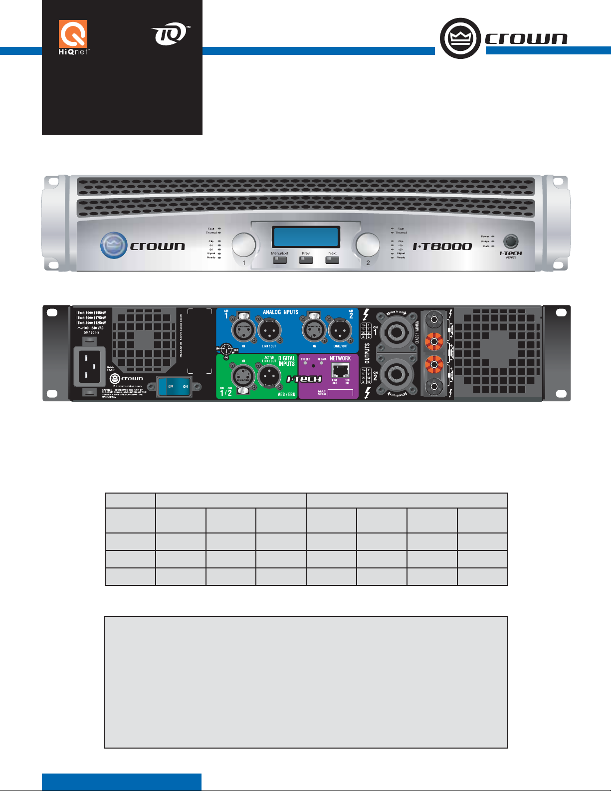
I-Tech Series
I-TECH 4000, 6000, 8000
power amplifi ers for touring sound
Power Output Guaranteed minimum power in watts at 20 Hz-20 kHz with 0.35% THD
2-ohm Dual (per ch.)
Model
Name
I-T4000 2,565W
I-T6000 4,570W
I-T8000 5,900W
20 mS
BURST
20 Hz - 20
kHz 1 kHz
1,800W 1,800W 2,000W 1,250W 3,600W 4,000W
2,500W 2,500W 3,000W 1,500W 5,000W 6,000W
3,500W 3,500W 4,000W 2,100W 7,000W 8,000W
Features
• Global Power Supply – designed to deliver
maximum power no matter where your schedule
takes you
• Studio Quality Processing – integrated processing reduces DSP noise for a quieter overall
system
• Peak voltage and RMS power limiting protects
your speaker investment
4-ohm Dual
(per ch)
• Front panel LCD provides diagnostics and
preset selection to ensure fast and easy system
setup
• Front panel lockout – ensures that tunings and
presets are safely stored and protected from
curious users
• Remote monitoring and control for complete
system control anywhere in the venue
8-ohm Dual
(per ch)
4-ohm
Bridge
8-ohm
Bridge
Page 2
Specifi cations
Performance
Frequency Response (at 1 watt, 20 Hz - 20 kHz):
±0.25dB.
Signal to Noise Ratio below rated full-bandwidth power,
A-weighted: > 105 dB.
Total Harmonic Distortion (THD) at full rated power:
< 0.35%.
Intermodulation Distortion (IMD) 60 Hz and 7 kHz at
4:1, from full rated output to –35 dB: < 0.35%.
Damping Factor (20 Hz to 100 Hz at 8 ohms): > 5000.
Crosstalk (below rated power, 20 Hz to 1 kHz):
> 80 dB.
Common Mode Rejection (CMR) (20 Hz to 1 kHz):
> 50 dB.
DC Output Offset (shorted input): < ± 3 mV.
Input Impedance (nominal): 20 kilohms balanced,
10 kilohms unbalanced.
Maximum Input Level: +15 dBu or +21 dBu, depending
on input sensitivity.
Latency (analog, digital inputs): 1.13 mS analog, 1.81
mS digital (96 kHz).
A/D, D/A Converters: 24-bit 96 kHz Cirrus Logic.
Digital Input: AES/EBU, 24-bit, 32-96 kHz. Onboard
sample-rate converter.
Network: Onboard TCP/IQ and HiQnet, compatible with
standard 100 Mb Ethernet hardware.
DSP: 24-bit conversion with 32-bit, fl oating-point DSP
processing. Has 64 assignable fi lters with 9 different fi lter
types. Includes all-pass fi lters, over 2 seconds of delay
available per channel, and dual uncorrelated-noise and
sine-wave generators.
Load Supervision: Monitors the average impedance on
the output of the amplifi er. If the impedance falls outside
the specifi ed high/low limits, this function alerts the user
via the front panel display, and via System Architect or
IQwic™ software.
Error Reporting: Reports clip errors, thermal errors, fault
conditions and load monitoring errors for each channel
via the front panel display and via System Architect or
IQwic software when amp is on a network.
Attenuators: Speed sensitive, continuously variable rotary
encoder, 0.5 dB steps, range 0 to –100 dB.
Load Impedance: (Note: Safe with all types of loads)
Stereo: 1/2/4/8/16 ohms.
Bridge Mono: 2/4/8 ohms.
Input Sensitivity (referenced to 8 ohm rated output):
Adjustable in 0.1V steps from 1.4V to 7.75V.
Voltage Gain (referenced to 8 ohm rated output):
I-T4000: 37.1 dB to 22.2 dB
I-T6000: 37.9 dB to 23.0 dB
I-T8000: 39.3 dB to 24.5 dB
Required AC Mains: Universal AC input, 100-240VAC,
50/60 Hz (±15%). Maximum AC mains voltage 277VAC.
AC Line Connector: Five cordsets supplied with amplifi er
(USA, UK, European, Australia, India).
Front Panel Controls and Indicators
Bridge Mode Indicator: Yellow LED illuminates when the
amplifi er is set to Bridge-Mono mode.
Ready Indicator: Green LED, one per channel, illuminates
when the channel is initialized and ready to produce audio
output. Indicator is off when the amplifi er is in standby
mode via the control software.
Signal Indicators: Three green LEDs per channel indicate
the amplifi er’s input and output signal levels.
Signal: input signal is above –40 dBu.
–20 dB: amplifi er output is 20 dB below clipping.
–10 dB: amplifi er output is 10 dB below clipping.
Clip Indicator: Red LED, one per channel, illuminates
when the channel’s output signal reaches the onset of
audible clipping. The Clip Indicator also will illuminate
during Thermal Level Control (TLC) limiting.
Thermal Indicator: Red LED, one per channel, illuminates
when the channel has shut down due to thermal stress
or overload.
Fault Indicator: Red LED, one per channel, fl ashes when
the amplifi er output channel has stopped operating.
Data Indicator: Yellow LED indicates network data activity. Data indicator fl ashes only when the amplifi er is polled
for data, or is polled to see whether it is online
Power Indicator: Blue LED indicates amplifi er has been
turned on and AC power is available. The LED will fl ash
when the AC line voltage is 15% above or below the
nominal rated value.
AC Mains Present Indicator: Green indicator built into
power switch indicates AC power is present at the power
cord and the amplifi er circuit breaker is in the “on”
position.
LCD Control Screen and Controls: These let the user
adjust the amplifi er’s attenuation and muting, confi gure
the amp, set up and view error monitoring (such as temperature and load supervision), and recall DSP presets.
The presets allow the user to quickly reconfi gure the amp
for various applications.
LCD Control Screen: Integrated LCD with white LED
backlight, controls amplifi er setup and operation.
Normal mode: Attenuation in 0.5 dB steps, Mute/
Unmute, Front Panel Lockout.
Basic Menu: LCD Contrast, CH1 Sensitivity, CH2 Sensitivity, Speaker Preset, Dual/Bridge mode, Input Y.
Advanced Menu: Attenuator Limits, Attenuator Link,
Clip Limiter, Peak Voltage Limiter, Average Power Limiter, Pink Noise Generator, AES/EBU Input Trim, Input
Source, Maximum Analog Input, Meter Display Type.
Monitor Menu: Speaker Load, Thermal %, AC Voltage,
Operating Time, Firmware, Manufacturing Info, Networking, Thermal Errors, Clip Errors, Low Limit Load
Errors, High Limit Load Errors, Line Voltage Errors.
Menu/Exit Button: “Menu” enters the main menu.
“Exit” gets out of the Menu.
Next Button: Selects the next item in the Menu.
Prev Button: Selects the previous item in the Menu.
Level Controls (Encoders): Speed-sensitive rotary
encoders, 0.5 dB steps, range 0 to –100 dB. These
two knobs affect the Channel-1 and Channel-2 output
levels. They also select Menu items and adjust parameter values that are displayed on the LCD Control
Screen.
Power Switch: Push-on/push-off switch with built-in
green AC mains present indicator.
Back Panel Controls, Indicators and Connectors
Power Cord Connector: Standard 20 amp IEC inlet. Volt-
age range is indicated above IEC inlet.
Reset Switch/Circuit Breaker: If the current draw of the
I-Tech Series
amplifi er exceeds safe limits, this breaker automatically
disconnects the power supply from the AC mains. The
switch resets the circuit breaker.
Output Connectors: Two high-current, 50A Neutrik®
Speakon® NL4MLP (mates with NL4FC or NL4), one per
channel. Two pairs of high-current, 60A color-coded 5way binding posts (for banana plugs, spade lugs or bare
wire). Two male XLR passive analog loop through. XLR
active/re-clocked AES/EBU digital loop through.
Analog Input Connectors: A 3-pin female XLR connector
for each channel.
Digital Input Connector: A 3-pin female XLR connector
that accepts a digital signal in the AES/EBU format.
Network Connector: This Ethernet connector accepts an
RJ-45 connector for TCP/IQ or HiQnet networking. Built
into the connector is a yellow LINK ACT indicator that
shows network activity, and a green 100Mb indicator that
shows a 100Mb network connection.
Data Indicator: Yellow LED indicates network data activity. Data indicator fl ashes only when the amplifi er is polled
for data, or is polled to see whether it is online.
Preset Indicator: Yellow LED fl ashes to signal the number
of the current preset if active.
Construction
Cooling: Dual-zone, microprocessor controlled, continu-
ously variable speed fans, front-to-back airfl ow.
Front Panel: Cast aluminum with integrated handles.
Dimensions: 19 in. (48.3 cm) W x 3.5 in. (8.9 cm) H x
16.2 in. (41.1 cm) D.
Weight: 28 lbs (12.7 kg) net, 36 lbs (16.3 kg) shipping.
Included Accessories: Rear rack ears, rack screws,
operation manual, power cords, foam air fi lter.
Crown International
1718 W. Mishawaka Rd.
Elkhart, IN 46517-9439
TEL: 574-294-8200
FAX: 574-294-8FAX
Customer Service: 800-342-6939
or 574-294-8200.
www.crownaudio.com
Specifi cations subject to change without prior notice. Latest
information available at www.crownaudio.com.
Crown Audio is a registered trademark of Crown International.
HiQnet is a trademark of Harman International Industries, Inc.
Other trademarks are the property of their respective owners.
Printed in U.S.A.
© 2007 Crown Audio
®
Inc
8/07 140318-1A
 Loading...