

Page 1

DC-300A
w
crolun
INSTRUCTION MANUAL
IM-9
S3P2-15-6
SERIAL NO
ISSUED
DC-300A
DUAL CHANNEL
LABORATORY AMPLIFIER
CROWN INTERNATIONAL, INC., BOX 1000, ELKHART, INDIANA 46514
Page 2
w
crown
0
In-runaTlonac
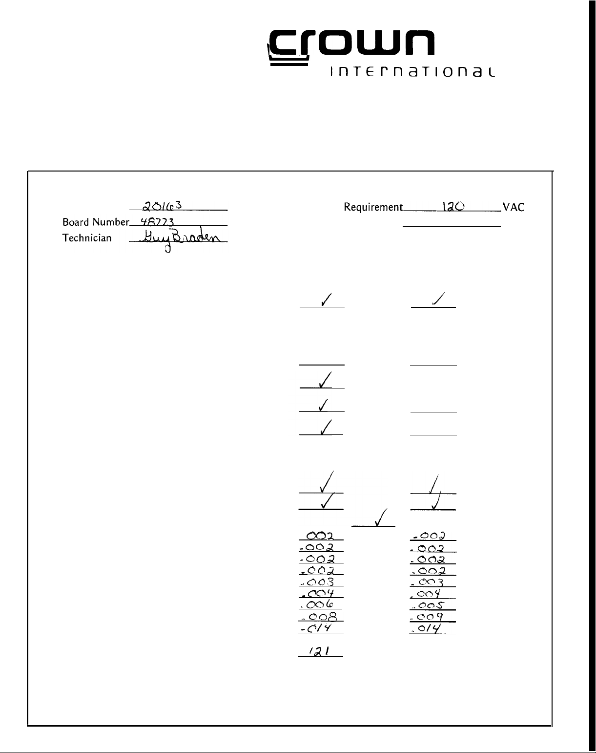
BATCH ID
DCA-11
Proof of Performance Report
DC-300A laboratory power amplifier
Serial Number
1. Quies. offset of less than
2.
1 KHz 180 watts
8 ohms, per channel, both channels
operating, 0.1% total harmonic
distortion
RMS
minimuminto
1OmV
Line Voltage
Amcron Label
CH.l
Requirement\ao,VAC
J
SERIAL NO
020163
CH.2
J
3.
4 ohm test
4. Protection tests
5.
Reliability test
6. 20KHz 155 watts per channel
minimum RMS (both channels
operating) into 8 ohm. 0.05% total
harmonic distortion
7.
10 KHz. sq. wave
8. Mono operation
9.
IM Dist. into 8 ohms (%)
(60-7KHz
10.
Hum and noise-db below
8 ohm (20Hz
4:1)
S.M.P.T.E.
-
20KHz)
155W
into
-002
-002
*
c?oJ.
_ cl03
_ @O’j
.00cc
..
c
ci/ Y’
‘2 1
z
49mW
db
155W
49.0W
15.5w
4.9w
1.55w
490mW
155mW
15.5mW
Page 3

‘TOTAL
PERFORMANCE
IS WHAT COUNTS"
CROWN test and check-out procedures reflect our basic design
philosophy; we believe that reliability can be engineered into a
product. As such, our check-out is designed to expose and
correct a problem, before it happens. This testing begins when
the unit is still a pile of parts; grading and selection of
components is standard. The final test-inspection is the culmination of this vigorous program, but our concern doesn’t stop here.
Our products are backed by an extensive field service program,
and protected by a comprehensive warranty.
A word about our testing procedure is in order. All
cations are referenced to an AC input of 120 VAC. The high
current demand with high power tends to cause the line voltage
to sag, or the sinusoidal waveform to distort. With a distorted
waveform (or lower line voltage) the peak voltage is lowered.
Since it is the peaks that charge the filter capacitors in the
amplifier power supply, and thus determine the maximum power
output, a line voltage problem reduces the maximum power
output. CROWN uses a peak equivalent AC voltmeter which
measures the peaks of any waveform and converts this to an
equivalent rms reading for a sinusoidal waveform. This way we
can vary or regulate the line voltage, no matter how distorted
the waveform, to an equivalent of a 120 VAC sinewave. We are
then measuring a true maximum output power.
With regard to the precision load which we use for our testing,
we realize that a resistive load is quite different than a reactive
speaker. However, using readily available parts, a precision
resistive load is the easiest to duplicate, with respect to
obtaining consistent results. We specify that the load must be
resistive, having less than 10% reactive component at any
frequency up to five times the highest test frequency. The
resistance value should be maintained within
levels.
The following discussion examines each of the test procedures
listed on the facing page. This is an attempt to help you understand, in layman’s terms, what the tests mean.
Quiescent Offset
amplifier’s output is balanced with reference to its input.
Thus the amplifier will not “bias” the program with a
dc component. To meet specifications, offset must be less
than 10 mv.
1KHz -
This test measures the power across an 8 ohm
load at
a frequency of 1 KHz with both channels operating.
This is a determination of how much power an amplifier
can produce before a specified total harmonic distortion
is reached. For the
at less than
4 Ohm Test
performance at impedances below that for which it is
rated. We check the wave form for level (it must reach a
specified voltage before clipping) purity, and stability.
-
This simply
DC-300A,
.1%
THD.
-
This is a critical examination of the DC-300’s
assures
the power is 180 watts
our specifi-
1%,
at all power
that your
Protection Test
4.
determines the threshold at which the protection circuitry
will be activated. Sharp clipping should occur with no
evidence of instability. The positive and negative limiters
operated independently and therefore may not be activated
simultaneously.
5.
Reliability Test
an extremely vigorous
low frequency input signal driving the output to full
power across a short circuit for a predetermined period of
time.
6.
20KHz
-
We specify that at any frequency between 1Hz and
2OKHz the DC-300A will produce 155 watts minimum
rms (both channels operating) into an 8 ohm load, at a
sum total harmonic distortion of .05% or less. We choose
20KHz
as the test frequency because high frequencies
produce more heat than lower frequencies. Thus, if the
amplifier can safely pass the
safely at lower frequencies.
10 KHz Square Wave
7.
amplifier’s frequency response and rise time. (How fast
the amplifier can follow rapid signal changes.) The output
square wave (with an 8 ohm load) should be clean and
sharp, with no ringing or overshoot.
Mono Operation
8.
the stereo mono switch. A signal is applied to channel 1
input only and the mono output is observed between the
two red output terminals of the amplifier.
IM
Distortion Test - At CROWN we feel that IM
9.
distortion testing yields a truer picture of amplifier
performance than harmonic distortion testing. While a
large amount of documentation supports this opinion,
some of the reasons are apparent, even in layman’s terms.
For example, a sinusoidal waveform (used in HD testing)
bears little resemblance to the complex waveforms
associated with actual program materials. IMD testing
uses such a complex waveform. Also, harmonic distortion
is not always aurally offensive. The human ear may
interpret such distortion as pleasing, but usually finds IM
distortion rather obnoxious. In order to support this
design philosophy, we designed and built our own IM
analyzer with residual noise and distortion low enough to
test our amplifiers.
Hum and Noise
10.
small a signal can be amplified without it becoming “lost
in the mud”. The test is limited to the audio band width
of
20Hz-20KHz,
for the DC-300A is: hum and noise from
will be at least
watts. This means that with a 155 watt output the noise
will be only
of a watt
11.
Quiescent AC power Input at 120 VAC - This test
confirms that your amplifier is not drawing excessive
power while “idling”. If an amplifier exhibits a tendency
toward instability, or oscillation, it may draw power with
no signal input. The DC-300A will draw 40 watts or less
at idle.
-
This is a test with a 2 ohm load which
-
This test puts the output stages through
thermal
cycling. The test is a very
This tests the amplifier at its rated power level.
20KHz
test, it will operate
-
This test critically examines the
-
This is a check for proper operation of
-
This test, in plain English, tells you how
with a bandpass filter. Our specification
110db
below the full power output of 155
.00155
micro watts. (That’s 1.55 billionths
)
20Hz
-
20KHz
Page 4

Section 1 DESCRIPTION
1
.1
General
Specifications
1.2
Warranty
1
.3
Section 2 INSTALLATION
Unpacking
2.1
2.2 Mounting
Normal
2.3
2.4 Connecting Output Lines ................................................................................................,
2.4.1
Section 3 OPERATING INSTRUCTIONS
MonoOperation
Connecting
2.5
Connecting
2.6
Controls
3.1
The
3.2
OperatingPrecautions
3.3
Load
3.4
Cleaning
3.5
. . . . . . . . . . . . . . . . . . . . . . . . . . . . . . . . . . . . . . . . . . . . . . . . . . . . . . . . . . . . .
. . . . . . . . . . . . . . . . . . . . . . . . . . . . . . . . . . . . . . . . . . .. . . . . . . . . . . . . . . . . . . . . . . . . . . . . . . . . . . . . . . . . . . . . . . . . . . . . . . . . . .
. . . . . . . . . . . . . . . . . . . . . . . . . . . . . . . . . . . . . . . . . . . . . . . . . . . . . . . . . . . . . . . . . . . . . . . . . . . . . . . . . . . . . . . . . . . . . . . . . . . . . . . . . . . . . . . . . . . . . . . .
. . . . . . . . . . . . . . . . . . . . . . . . . . . . . . . . . . . . . . . . . . . . . . . . . . . . . . . . . . . . . . . . . . . . . . . . . . . . . . . . . . . . . . . . . . . . . . . . . . . . . . . . . . . . . . . . . . . . . . . .
. . . . . . . . . . . . . . . . . . . . . . . . . . . . . . . . . . . . . . . . . . . . . . . . . . . . . . . . . . . . . . . . . . . . . . . . . . . . . . . . . . . . . . . . . . . . . . . . . . . . . . . . . . . . . . . . . . . . . . . .
Installation
Hi-Fi
. . . . . . . . . . . . . . . . . . . . . . . . . . . . . . . . . . . . . . . . . . . . . . . . . . . . . . . . . . . . . . . . . . . . . . . . . . . . . . . . . . . . . . . . . . . . . . . . . . . . . . . . . . . . . . . . .
Lines
Input
Power
and Adjustments
Protection
Protection
. . . . . . . . . . . . . . . . . . . . . . . . . . . . . . . . . . . . . . . . . . . . . . . . . . . . . . . . . . . . . . . . . . . . . . . . . . . . . . . . . . . . . . . . . . . . . . . . . . . . . . . . . . . . . . . . . . . . . . . .
. . . . . . . . . . . . . . . . . . . . . . . . . . . . . . . . . . . . . . . . . . . . . . . . . . . . . . . . . . . . . . . . . . . . . . . . . . . . . . . . . . . . . . . . . . . . . . . . . . . . . . . . . . . . . .
Mechanisms
Methods
. . . . . . . . . . . . . . . . . . . . . . . . . . . . . . . . . . . . . . . . . . . . . . . . . . . . . . . . . . . . . . . . . . . . . . . . . . . . . . . . . . . . . . . . . . . . . . . . . . .
. . . . . . . . . . . . . . . . . . . . . . . . . . . . . . . . . . . . . . . . . . . . . . . . . . . . . . . . . . . . . . . . . . . . . . . . . . . . . . . . . . . . . . . . . . . . . . . . . . . . .
. . . . . . . . . . . . . . . . . . . . . . . . . . . . . . . . . . . . . . . . . . . . . . . . . . . . . . . . . . . . . . . . . . . . . . . . . . . . . . . . . . . . . . . . . . . . . . . . .
. . . . . . . . . . . . . . . . . . . . . . . . . . . . . . . . . . . . . . . . . . . . . . . . . . . . . . . . . . . . . . . . . . . . . . . . . . . . . . . . . . . . . . . . .
. . . . . . . . . . . . . . . . . . . . . . . . . . . . . . . . . . . . . . . . . . . . . . . . . . . . . . . . . . . . . . . . . . . . . . . . . . . . . . . . . . . . . . . . . . . . . . . . . . . . . . .
. . . . . . . . . . . . . . . . . . . . . . . . . . . . . . . . . . . . . . . . . . . . . . . . . . . . . . . . . . . . . . . . . . . . . . . . . . . . . . . . . . . . . . . . . . . . . . . . . .
TABLE OF
. . . . . . . . . . . . . . . . . . . . . . . . . . . . . . . . . . . . . . . . . . . . . . . . . . . . . . . . . . . . . . . .
CONTENTS
..
2,
PAGE
..
3, 4, 5
12
...
13
..
13
..
13
14
16
16
17
19
19
.
21
21
22
...
1
Section 4 CIRCUITRY
Principles
4.1
Test
4.2
Service. . . . . . . . . . . . . . . . . . . . . . . . . . . . . . . . . . . . . . . . . . . . . . . . . . . . . . . . . . . . . . . . . . . . . . . . . . . . . . . . . . . . . . . . . . . . . . . . . . . . . . . . . . . . . . . . . . . . . . . . . ......
4.3
Section 5 APPLICATION NOTES
Application
Application
Application Note No. 3
TITLE
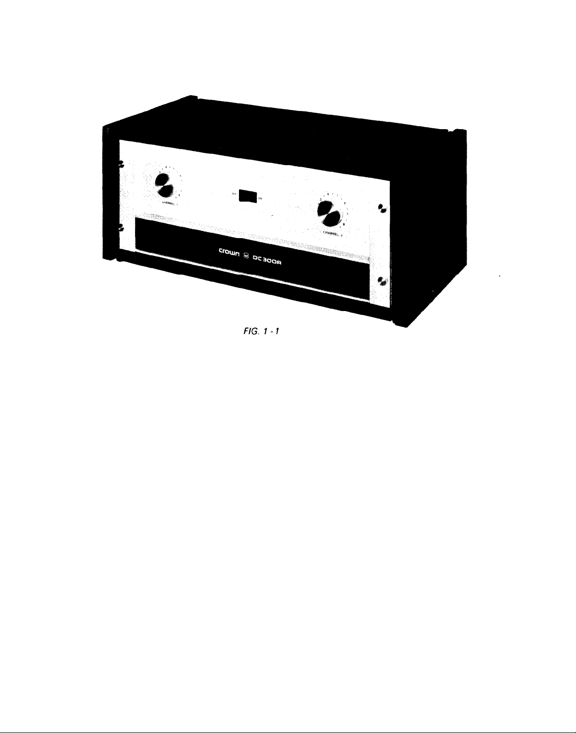
DC-300A
l-l
l-2 DC-300A Performance Graphs
I.M. Distortion
Harmonic
Frequency
Power
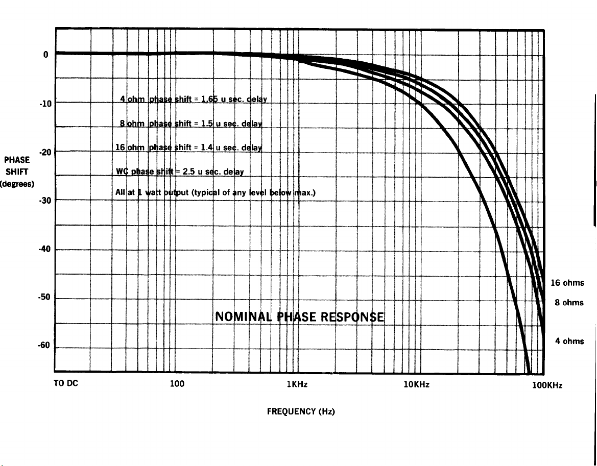
Phase
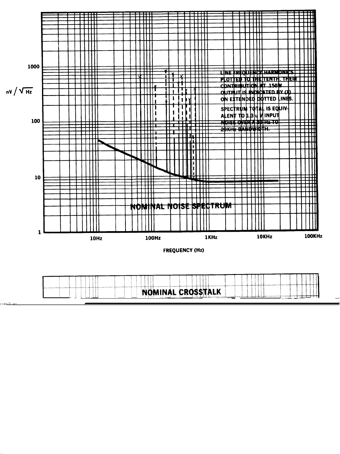
Noise
Crossta Ik
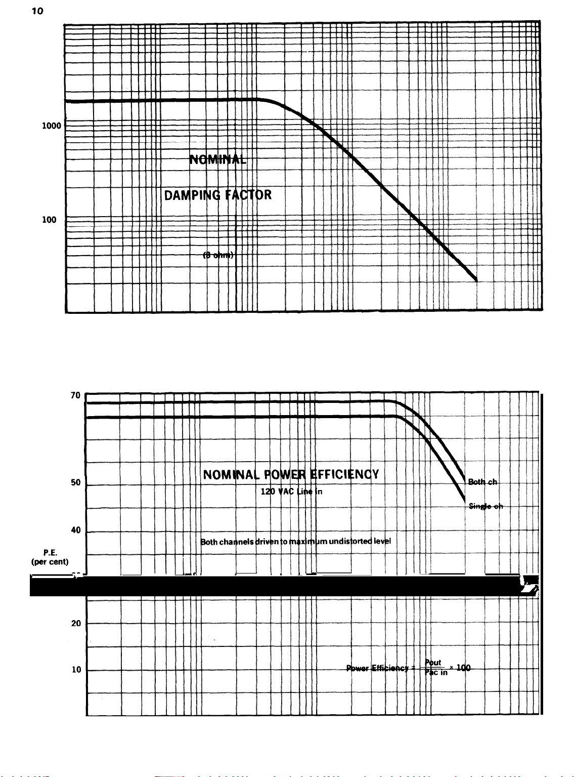
Nominal
Damping
Power
Input
of Operation
Procedures
Pictorial
Distortion
Response
Response
Spectrum
. . . . . . . . . . . . . . . . . . . . . . . . . . . . . . . . . . . . . . . . . . . . . . . . . . . . . . . . . . . . . . . . . . . . . . . . . . . . . . . . . . . . . . . . . . . . . . . . . .._..............
Limits
Factor
Efficiency
Impedance
. . . . . . . . . . . . . . . . . . . . . . . . . . . . . . . . . . . . . . . . . . . . . . . . . . . . . . . . . . . . . . . . . . . . . . . . . . . . . . . . . . . . . . . . . . . . . . . . . . . . . . . . . . . . . . . . .
Note No.
Note
Response
1 - V-l
No.2 -
. . . . . . . . . . . . . . . . . . . . . . . . . . . . . . . . . . . . . . . . . . . . . . . . . . . . . . . . . . . . . . . . . . . . . . . . . . . . . . . . . . . . . . . . . . . . . . . . . . . . . . . . . . . . . . . .
. . . . . . . . . . . . . . . . . . . . . . . . . . . . . . . . . . . . . . . . . . . . . . . . . . . . . . . . . . . . . . . . . . . . . . . . . . . . . . . . . . . . . . . . . . . . . . . . . . . . . . . . . . . . . . . . . . . . . .
. . . . . . . . . . . . . . . . . . . . . . . . . . . . . . . . . . . . . . . . . . . . . . . . . . . . . . . . . . . . . . . . . . . . . . . . . . . . . . . . . . . . . . . . . . . . . . . . . . . . . . . . . . . . .
. . . . . . . . . . . . . . . . . . . . . . . . . . . . . . . . . . . . . . . . . . . . . . . . . . . . . . . . . . . . . . . . . . . . . . . . . . . . . . . . . . . . . . . . . . . . . . . . . . . . . . . . . . . .
. . . . . . . . . . . . . . . . . . . . . . . . . . . . . . . . . . . . . . . . . . . . . . . . . . . . . . . . . . . . . . . . . . . . . . . . . . . . . . . . . . . . . . . . . . . . . . . . . . . . . . . . . . . . . . . . . .
. . . . . . . . . . . . . . . . . . . . . . . . . . . . . . . . . . . . . . . . . . . . . . . . . . . . . . . . . . . . . . . . . . . . . . . . . . . . . . . . . . . . . . . . . . . . . . . . . . . . . . . . . . . . . . . . . . .
. . . . . . . . . . . . . . . . . . . . . . . . . . . . . . . . . . . . . . . . . . . . . . . . . . . . . . . . . . . . . . . . . . . . . . . . . . . . . . . . . . . . . . . . . . . . . . . . . . . . . . . . . . . . . . . . . . . .
of V-lOutput
. . . . . . . . . . . . . . . . . . . . . . . . . . . . . . . . . . . . . . . . . . . . . . . . . . . . . . . . . . . . . . . . . . . . . . . . . . . . . . . . . . . . . . . . . . . . . . . . . . . . . . . . . . . . . . . . . .
. . . . . . . . . . . . . . . . . . . . . . . . . . . . . . . . . . . . . . . . . . . . . . . . . . . . . . . . . . . . . . . . . . . . . . . . . . . . . . . . . . . . . . . . . . . . . . . . . . . . . . . . . . . . . . . .
vs.
Gain
. . . . . . . . . . . . . . . . . . . . . . . . . . . . . . . . . . . . . . . . . . . . . . . . . . . . . . . . . . . . . . . . . . . . . . . . . . . . . . . . . . . . . . . . . . . . . . . . . . . . . .
Limits of a
VFX-2
-
Speaker Protection . . . . . . . . ....................................................... 29
. . . . . . . . . . . . . . . . . . . . . . . . . . . . . . . . . . . . . . . . . . . . . . . . . . . . . . . . . . . . . . . . . . . . . . . . . . . . . . . . . . . . . .
. . . . . . . . . . . . . . . . . . . . . . . . . . . . . . . . . . . . . . . . . . . . . . . . . . . . . . . . . . . . . . .
Load
23
24
24
25
27
LIST OF ILLUSTRATIONS
PAGE
1
5
5
6
6
7
8
8
. . . . . . . . . . . . . . . . . . . . . . . . . . . . . . . . . . . . . . . . . . . . . . . . . . . . . . . . . . . . . . . . . . . . . . . . . . . . . . . . . . . . . . . . . . . . . .
. . . . . . . . . . . . . . . . . . . . . . . . . . . . . . . . . . . . . . . . . . . . . . . . . . . . . . . . . . . . . . . . . . . . . . . . . . . . . . . . . . . . . . . . . . . . . . . . .
9
10
10
11
Page 5

2-l
2-2
2-3
2-4
2-5
2-6
2-7
2-8
2-9
2-10
3-l
3-2
3-3
3-4
3-5
Maximum Output vs. Load Impedance
output
output IL I..
Mounting Dimensions
Normal Hi-Fi Hook-up
Rear View of Chassis
............................................................................................................................
(Z)
.
...........
..............................................................................................................
.......................................................................................................
...........
......
.............................................................................................
..................................................................................................
Source Resistance and Damping Factor vs. Length and Size of Output Leads
Schematic For Full Range Electrostatic Speaker Connections
Schematic of Earphone Pad
DC-3ODA Mono Hook-up
..............................................................................................
...................................................................................................
Table For Selection of Input DC Blocking Capacitor
Low-Pass
Filter
For
Severe
RFAtInputs
Table of Line Voltage Connections
.....................................................................................................
Operating
Controls
........
Graph of VI Operating Range of DC-300A Output
For
Fuse
Selector
RelayControlled
Nomograph
Protector with
Turn-On-Transient
Muter
Loudspeaker
Overload
ForLoad
............................................................................
............
......................................
.......................................................
.........................................................................
...................................................................................
.........................................................
Protection
Indicator
Protection
................................................................
..................................................
........................................................
11
1 2
12
13
14
14
15
15
16
16
17
17
18
19
20
22
22
22
Page 6
1 .1 GENERAL
Section 1
DESCRIPTION
DC-300A PICTORIAL
The DC-300A is a dual-channel high-power amplifier for
precision amplification of frequencies from DC to
The unit features extremely low harmonic and
ulation distortion, very low noise, highest “damping
factor,”
the large output power, It is possible to obtain a monaural
70-volt balanced line without using an output transformer.
The DC-300A contains a new CROWN developed Signal
Programmed Automatic Current Executor (SPACE
control) electronic amplifier protection circuit which
manifests no
audio frequencies any impedance load including totally
reactive loads may be driven with no adverse effects.
Only maximum output power will be affected by variations in load impedance. At sub-sonic to DC frequencies
the limiter acts as a VI limiter to provide optimum protection for the extremely rugged silicon hometaxial
output devices (total of 16 for a total of 2400W dissipation).
A pair of thermal switches remove power from the unit
if overheating occurs due to insufficient ventilation, The
AC line is fused to protect the power supply.
See Section 3.2 for a description of the protective systems.
and quality parts and workmanship. Because of
flyback
pulses, thumps, or shut-down. At
20KHz.
intermod-
26 diodes, 1 bridge rectifier, and 3 zener diodes are used in
the
DC-3OOA
effective number of semiconductors is 60 transistors, 30
diodes, and 3 zener diodes.
The output devices, 8/channel, are conservatively employed, having a total peak current rating/channel of 120
amps in a circuit that is limited to a maximum of 28
amps. Among its unique features, the circuitry includes
the CROWN-pioneered and patented
figuration.
The input operational amplifiers are powered by two
voltage-regulated supplies. This results in complete
channel-to-channel isolation and independence from line
voltage variations.
Total direct coupling results in perfect, instantaneous,
thump-free overload recovery even on non-symmetrical
waveforms. This cannot be said for any AC-coupled
amplifier presently in existence. Turn-on is instantaneous
with no program delays.
circuitry. With the integrated circuit, the
AB+B
output con-
The power supply features a 1 KW transformer and large
computer-grade filter capacitors giving over 48 joules
of energy storage.
A total of 44 discrete transistors, 1 linear IC (dual op amp),
Front-panel controls include two independent heavy-duty
level controls and a power switch with an associated pilot
light. DC balance controls, which never need adjustment
in normal operation, are located behind the front-panel.
Page 7

1.2 SPECIFICATIONS
1.2.1 STEREO SPECIFICATIONS
Output Power
Frequency Response
1 KHz Power
Harmonic Distortion
I.M. Distortion
(60Hz-7KHz 4:1)
Slewing Rate
Damping Factor
Output Impedance
Load Impedance
Voltage Gain
Input Sensitivity
Output Signal
155 watts per channel minimum RMS (both channels operating) into an 8 ohm load over a bandwidth of 1
Hz-20KHz
at
a rated RMS sum total harmonic distortion of 0.05% of the
fundamental output voltage.
±0.1dB DC-20KHz
180 watts RMS into 8 ohms, per channel, both channels operating, 0.1% total harmonic distortion.
Less than 0.001% from
per channel into 8 ohms.
Less than 0.05% from 0.01 watts to 0.25 watts and less than 0.01% from 0.25 watts to
into 8 ohms, per channel.
8 volts per microsecond (slewing rate is the maximum value of the first derivative of the output
signal, or the maximum slope of the output
Greater than 750,
Less than 7 milliohms in series with less than 3 microhenries.
Rated for 8 ohm usage; safely drives any load Including completely reactive loads.
20.6±2%
1.75
Unbalanced, dual channel.
or
volts±2%
at 1 watt into 8 ohms;
20Hz-400Hz.
DC-400Hz
26.3±0.2dB
for 155 watts into 8 ohms.
into 8 ohms.
at maximum
±ldB DC-100KHz.
and increasing linearly to 0.05% at 20KHzat 155watts RMS
155watts
signal).
gain.
Page 8

1
.2.2
MONAURAL SPECIFICATIONS
Output Power
Frequency Response
1 KHz Power
Harmonic Distortion
I.M. Distortion
Slewing Rate
Damping Factor
Output impedance
Load Impedance
Voltage Gain
Input Sensitivity
Output Signal
310 watts minimum RMS into a 16 ohm load over a
bandwidth of 1
Hz-20KHz
at a rated RMS sum total harmonic distortion of 0.05% of the fundamental output
voltage.
±0.15dB,
360 watts RMS into 16 ohms.
Less than 0.001% from
16 ohms.
Less than 0.05% from 0.01 watts
into 16 ohms.
16 volts per microsecond.
Greater than 700, DC-400Hz into 16 ohms.
Less than 15 milliohms in series with less than 6 microhenries.
Rated for 16 ohm usage; safely, drives any load including completely reactive loads.
41.2±2% or 32.3±0.2dB at maximum gain.
1.75 volts for 310 watts into 16 ohms.
Balanced, single channel.
DC-20KHz
at 1 watt into 16 ohms; ±1
20Hz-400Hz
and increasing linearly to 0.05% at 20KHz at 310 watts into
to 0.25
watts and less than 0.01% from 0.25 watts to
dB, DC-6OKHz
at 1 watt into 16 ohms.
310 watts
Page 9

4
1.2.3 GENERAL SPECIFICATIONS
below rated output
Hum and Noise
(20Hz-20KHz)
Phase Response
Input Impedance
110dB
-15°
+0,
100K
Zero to
ohms at minimum gain,
20KHz
at 1 watt
10K
ohms at maximum gain.
Amplifier Output
Protection
Overall Protection
Turn-on
Circuit
Power Supply
Power Requirements
Heat Sinking
Chassis
Controls
Connectors
Short, mismatch, and open circuit proof. Limiting is instantaneouswith noflyback pulses, thumps,
cutout, etc. No premature limiting on transients.
AC line fused. Thermal switch in AC line protects against overheating caused by insufficient
ventilation. Controlled slewing rate voltage amplifiers protect overall amplifier against RF burnouts. Input overload protection is furnished by internal resistance at inputs of amp.
instantaneous, with minimum thumps and no program delay.
Wideband
60 transistors, 30 signal diodes, 3 zeners and 6 rectifier diodes.
1 kilowatt transformer with massive computer-grade filter capacitors storing over 48 joules of
energy. Two regulated supplies for complete isolation and stability.
Requires
Draws 40 watts or less on idle, 500 watts at 300 watts total output.
Massive black-anodized heat sinks are thermally joined with the chassis, thereby utilizing the en-
tire amplifier as a heat sink.
All aluminum construction for maximum heat conduction and minimum weight.
front panel is a single extrusion.
Independent input level controls are on front panel. Power switch, with integral pilot light is on
front panel. Non-interacting DC balance controls are mounted behind front panel. A mono-stereo
switch is located above the input jacks on the rear panel.
Input - ¼ inch phone jack
Output - Color coded binding posts
AC Line
multiple feedback loop design utilizing one linear IC (dual op-amp). Total equivalent of
50-4OOHz
-
Three-wire (grounded) male connector on 5 ft. min. cable
AC with selectable taps for 100, 120, 200, 220 and 240V
±10%
Heavy
operation.
aluminum
Dimensions
Weight
Finish
19 inch standard rack mount (W.E. hole spacing), 7 inches high,
surface).
45 pounds
Satinized aluminum front panel, with gray suede Lexan insert.
9¾
inches deep (from mounting
Page 10
Page 11
Page 12
Page 13
10
TO DC
60
10
100
FREQUENCY (Hz)
1K
10K
1OOK
10
100
1KHz 1OKHz
FREQUENCY (Hz)
1OOKHz
Page 14

Page 15

Page 16

2.1 UNPACKING
Section 2
INSTALLATION
As soon as the amplifier shipment is received, please
inspect for any damage incurred in transit. Since the unit
was carefully inspected and tested at the factory, it left
the factory unmarred. If damage is found, notify the
transportation company immediately. Only the consignee
may institute a claim with the carrier for damage during
shipment. However, CROWN will cooperate fully in such
an event. Se sure to save the carton as evidence of damage for the shipper’s inspection.
Even if the unit arrived in perfect condition -as most do
it is advantageous to save the packing materials. They
will prove valuable in preventing damage should there
ever be occasion to transport or ship the unit. Note
the carton and internal pack - each is designed for protection during transit, particularly of the power transformer weighing over 25 Ibs. Do
this factory pack!
nof
ship the unit without
-
2.2 MOUNTING
The DC-3DDA is designed on a standard 19 inch rack
mounting format. However, it may be custom mounted
if sufficient support is provided. For dimensions see
Fig.
2-1.
In any circumstance, sufficient ventilation must
be provided for the unit. Good ventilation practice allows
air to flow completely under, around, and through the
amplifier. If the unit is placed above a horizontal surface,
7
-I-
r
an air space should be allowed above and below the unit.
If sufficient ventilation is not provided, the unit will
intermittently turn off due to the built-in thermal pro-
tection. Such a condition (if observed) will also be ac-
companied by a warm front-panel due to the integral
heat-sinking employed in the amplifier.
Applications requiring long sustained signals at high
power levels may require the use of a cooling fan.
2.3 NORMAL HI-FI INSTALLATION
1. Remove output covers, exposing dual binding-posts.
Two-conductor speaker cables must connect to the OUT-
PUTS using terminal lugs, tinned ends, or the special
“banana” plugs supplied with the
in-line fuses as recommended in the Accessory Bag and
Fig. 2-2. (Not needed with CROWN speakers.)
2. Since the DC-300A is a “basic amplifier,” the main
outputs of the control-center or “preamplifier” must be
connected via shielded audio-cables to the two jacks
marked INPUT. Use RCA-pin at preamp and standard
¼
inch phone-plug at the
The two cables should be tied parallel along their entire
length, using the accessory cable ties.
DC-300A.
DC-300A.
Connect the
FIG. 2
- 1
MOUNTING DIMENSIONS
3. U/L requirements specify a 3-wire AC power connector; however, proper connections to a switched outlet
on the control center require the use of a 3-to-2 wire
adapter. NOW, plug the AC into a switched outlet on the
control center.
4, Your Control Center may now be turned on. Then
advance the
(1
50°
clockwise).
When using the CROWN IC-150A Control-Center, the
VOLUME should attain almost full rotation (2 to 4 o’clock)
for loudest “concert-hall”volume. If at 3 o’clockthevolume
is low, increase the DC-300A input gain controls; if too
high, decrease the
To assure maximum enjoyment and full speaker protection, read the following detailed sections on OUTPUTS,
INPUTS and Chapter 3-OPERATION.
13
DC-300A
DC-300A
Input-Gain Controls about %-open
gains.
Page 17

CONTROL
CENTER
RIGHT
SPEAKER
3 to 2 WIRE ADAPTER
SWITCHED OUTLET
POWER CABLE _
/
/
lb---
JJ
MDP PLUGS
DUAL BANANA
IN-LINE FUSES
FIG. 2-2
NORMAL HI-N HOOK-UP
CABLE TIE(S)
NOTE! /
SHIELDED AUDIO CABLES MONO-STEREO SWITCH
Or A o’hl
TO ¼" PHONE
7)
LEFT
SPEAKER
2.4 CONNECTING OUTPUT LINES
Input and output connectors are located on the back of
the chassis as shown in Fig. 2-3.
It is always wise to remove power from the unit and turn
the input level controls off while making connections,
REAR OF CHASSIS
WITH OUTPUT COVERS REMOVED
especially
eliminate
liable for
its being overpowered! (CROWN speakers excepted.)
Before making connections, it is recommended that the
operator familiarize himself with the amplifier’s
tective system. See Section 3.2. Section 3.3 entitled
“Operating Precautions” should also be read.
Because of the location of the output connectors
coded binding posts), it will be easiest to make these
connections first. High-quality, dual “banana” plugs are
the preferred connections for permanent installations,
critical applications, and when testing the amplifier.
Because the output wire gauge and length raises the
resultant source impedance or lowers the Damping Factor
by adding its series resistance, the nomograph (Fig. 2-4)
if the load is a loudspeaker system. This will
any chance of loud blasts. CROWN is not
damage incurred to any transducer due to
pro-
(color-
Page 18

15
40
RL
LOAD
30
RESISTANCE
(ohms)
20
15
10
9
8
7
6
Rl
R,
DAMPING
7.
.04
s-.06
R,
-
--
SOURCE
.l
~MOOO ft.1
RESISTANCE
2-COND.
CABLE --
8000
5000
--ANNEALED
1000
T
COPPER
500.-
WIRE
IAWGI
50.---t24
5
4
FIG. 2-4
SOURCE RESISTANCE AND DAMPING FACTOR VS. LENGTH AND SIZE OF OUTPUT LEADS
is provided for wire selection. For dynamic moving-coil
loudspeakers the value of
RL
should preferably be that
measured by an ohmmeter across the voice coil, rather
than the manufacturer’s rating. For electrostatic speakers and such, the manufacturer’s rated impedance should
be used for R.
If the load (matching transformer, inductance, or
range electrostatic speaker system) appears as a
full-
short-
circuit at low frequencies, a large non-polarized
capacitor (paralleled with a resistor) should be placed
in series with the load.
For electrostatic speakers (if the manufacturer has not
provided a capacitor) an external non-polar capacitor of
590-708 mfd and 4 ohm power resistor should be placed
in series with the plus (+) speaker lead. This will prevent large low-frequency currents from damaging the
electrostatic transformer
activating the
DC-3OOA’s
or from
unnecessarily
protective systems. An ef-
fective test to determine if such parts are needed is to
F/G. 2-5
-
SCHEMA TIC FOR FULL RANGE
ELECTROSTATIC SPEAKER CONNECTIONS
measure the DC resistance between the output terminals
with an ohmmeter. If the resistance is less than 3 ohms,
the parts should be added as shown schematically
in Fig. 2-5.
When selecting connectors for the output lines, the follow-
ing general precautions apply (with all power connectors):
1. A male plug, carrying signal, must not be on the
far end of the line where it can be exposed, giving
rise to both shock and short-circuit hazards.
Page 19

16
Connectors which might accidentally cause the two
2.
channels to be tied together during making and
breaking of connection should not be used. A common
example is the standard 3-circuit
l/4
inch phone jack
and plug when wired for stereo sound.
Connectors which can be plugged into AC power
3.
receptacles should
Connectors having low-current-carrying capacity
4.
never
be used.
are “verboten.”
Connectors having any tendency to short, or having
5.
shorted leads, are unadvisable.
Most commercially-available headphones employ a 3-
circuit
l/4
inch phone plug which violates condition number
2. This is no handicap if a pad is inserted between the
amp and jack, which is the only sensible thing to do,
when such a large amplifier is coupled to such a small
transducer. If this precaution is ignored, not only may
the transducer be burned out but permanent hearing loss
could result. The recommended pad is shown in Fig. 2-6.
2.
Connect output lines as per the following drawing, Figure 2-7. The output from the
DC-3OOA
in Mono is BAL-
ANCED and is isolated from the chassis, and from the
input grounds to the DC-300A.
CAUTION: Be certain that all equipment (meters,
switches, etc.) connected to the Mono output lines is
balanced. Both sides of the line must be totally isolated
from the input grounds, to the DC-300A. If this is not ob-
served, severe oscillation may result.
lo
st.r.0
Earphenor
FIG. 2 - 6
SCHEMATIC OF EARPHONE PAD
2.4.1 MONO OPERATION
A mono-stereo switch on the rear panel adjacent to the in-
put jacks, allows the DC-300A to be operated normally
(stereo) or in mono, with no internal modification. (See
figure 2-2.) When in the mono position, the input circuitry of
the
DC-3OOA
is changed so that the two amplifiers are
“added” for mono output. (See mono specifications, page
3).
Care must be taken in the external hook-up to assure proper
operation. Proceed as follows:
The input line should be plugged into
1
the
channel 1 input
jack. The level is adjusted with the channel 1 input level
control.
NOTE: The Channel 2 input jack and level control are
not defeated in the Mono mode. However, the Channel 2
input should not be used in this mode. If a Channel 2
input is added to the Channel 1 input, distortion may
result. If Channel 2 input is used alone, very low power
output will result. For best results unplug the input to
Channel 2 when operating Mono.
FIG. 2-7
DC-300A MONO HOOK-UP
2.5 CONNECTING INPUT LINES
Connecting the inputs will require avoiding three basic
dangers: Undesirable signals to the inputs, “ground loops,”
and feedback from output(s) to input(s).
For loudspeaker-driving applications, the input should be
free of any DC, as this could cause overheating of the
loudspeaker voice coil. A simple visual test for DC on the
inputs (providing the woofer is visible) is to slowly turn up
the input level control with the amp on and watch for any
displacement of the cone. If very much displacement is
observed, the DC content of the input may be excessive and
require a blocking capacitor. The graph of Fig. 2-8 indicates
Page 20

the effect of the size of the blocking capacitor on the
frequency response. Only a low-leakage type paper, mylar,
or tantalum capacitor should be used for this purpose.
TABLE FOR SELECTION OF
INPUT DC BLOCKING CAPACITOR
If large amounts of ultrasonic or RF frequencies are found
on the input, such as bias from tape recorders, etc., a
pass filter should be placed on the input. While
obtainable RF input levels will not damage the amplifier,
they may cause burn-out of tweeters or other sensitive
loads, activate the amplifier’s protective systems, or cause
general overload in the controlled-slewing-rate stage of the
amp (which is employed to provide RF overload protection).
The following filters are recommended for such applications.
low-
practically-
power line may provide this feedback path. Proper
grounding, and isolation of inputs of common AC line
devices is good practice. Refer to Section 4.2, par. 5 for
testing precautions.
An extremely common form of this problem is encountered
when using electrostatic loudspeakers or any other kind of
load that is joined to the AC power mains. Capacitive
coupling through the load’s supplies may allow the
amplifier’s output to be fed through the AC mains and into
the grounds of input equipment resulting in a system
oscillation.
To combat the problem, first try reversing the speaker leads
on all channels if possible. If this does not solve the
problem, try grounding the power amplifier to the AC
ground with its 3 wire plug. (A ground loop may result
through an FM tuner with an earth-grounded antenna
system when deploying the 3 wire plug. The use of ,005
disc capacitors in series with the FM antenna leads will
eliminate
should of course be as short as reasonably possible, and a
turntable baseplate ground should always be broughtto the
phono preamp with a separate ground wire, never via the
input cable ground. If the oscillation still persists, start
thisproblem.)All hookup(interconnecting)cables
UF
removing input devices, working towards the amplifier until
the oscillation disappears. This will identify the point of
feedback. If an offending piece of equipment is found it
should be inspected for unnecessary AC line-to-ground
capacitances such as
line
filters,
etc. If possible such should
be removed. Such devices should never be found in the
load, although it is true that some RF loudspeakers have
used such filters to reduce
RFI.
FIG. 2-9
LOW-PASS FILTER FOR SEVERE RF AT INPUTS
A second problem area is “ground loops”
jargon for undesirable circulating currents flowing in a
grounding system. A common form of loop (possibly resulting in hum in theoutput)isapairof inputcableswhosearea
is subjected to a magnetic hum field. In practice, both
cables should lie
the power transformer. Tying the input and output grounds
together may also form a ground loop.
A third problem (with input and output grounds together, as
in testing or metering) is feedback oscillation, from load
current flowing in the loop. In industrial use, even the AC
together
along their length, and away from
-
electronic
2.6 CONNECTING POWER
The amplifier is furnished with a three-wire AC plug as
standard equipment. Adapters are readily available com-
mercially for adapting this to a two-wire system if necessary.
The amplifier offers five standard line-voltage connections: 100, 120, 200, 220, and 240VAC. The tag attached to
the line cord indicates for which voltage the amplifier is
connected. Most units are connected for
12OVAC.
When
changing the voltage to 200V or above, the external fuse,
Fl,
should be changed from 1 OA to 5A. Relabel the line tag
to indicate the proper voltage.
When testing the amplifier, the line voltage must be the
peak equivalent to a sinusoid of the indicated line voltage
when at full load. Line regulation problems can introduce
serious errors in the measurements on an amplifier of this
size.
Only a competent technician should attempt alteration of
the line voltage connections.
Page 21

In order to change the voltage, it is first necessary to
carefully detach the bottom cover from the unit. On the back
of the board-mount subchassis a terminal stripwith solder-
ALL VIEWS WITH BOTTOM PLATE REMOVED
on jumpers is used to make the line-to-transformer
primaries connections (see Fig. 2-10).
1oov
120v
See Note
2oov
220
v
I
I
I
I
L
I
240 V
See Note
NOTE: The 120V and 240V connections require the changeover of the RED
wire from TB-3 to TB-2. Therefore the front panel, control circuit-board and
shield must be carefully removed for access. When replacing shield, use
care so that on-off switch locates properly in front panel opening!
I
FIG.
2-10
TABLE OF LINE VOLTAGE CONNECTIONS
1
Page 22

Section 3
3.1 CONTROLS AND ADJUSTMENTS
OPERA TING CONTROLS
OPERATING INSTRUCTIONS
The DC-300A contains all the facilities essential for a
high performance amplifier.
On the front panel are located independent level controls,
a power switch, and pilot light. There is an AC line fuse
on the rear of the unit.
The level control should be adjusted for the desired
amplifier gain or output level. When the control is fully
CW, the gain is 26db as determined by precision 1%
resistors in the
The DC balance controls located behind the front panel
seldom, if ever, need adjustment.
critical applications will they need adjustment (not
“hi_fi”
balance controls, use the following procedures (see
Circuit Board layout in Section 4):
1.
Make sure amp has been allowed at least 15 minutes
of warm-up.
Set corresponding level control fully CCW.
2.
3.
Remove input signal from corresponding input.
Place sensitive DC voltmeter across output.
4.
5.
Adjust output balance control using small
bladed screwdriver for zero reading on voltmeter.
6.
Turn level control CW to 12 o’clock.
7.
Adjust input balance control using small
bladed screwdriver for zero reading on voltmeter.
The DC balance controls are now adjusted.
DC-300A’s
or similar applications). To adjust the DC
feedback loop.
Only
in the most
flat-
flat-
3.2 THE PROTECTION MECHANISMS
The DC-300A is protected against all the common
hazards which plague highpower amplifiers, including
shorted, open, and mismatched loads; overloaded power
supplies; excessive temperature;
phenomena; input overload damage; and high frequency
overload blowups.
Protection against shorted and low impedance loads is
provided by the Signal Programmed Automatic Current
Executor (SPACE control). It functions as an automatic
current limiter at audio frequencies whose value of
current limiting threshold is dependent on the history
of the output signal. Output current causes the threshold
to decrease while output voltage causes the threshold to
increase. The no signal threshold is high enough to
allow tone bursting, (even into 4 ohms) without premature
limiting as is found in some recent products of other manu-
facturers
Since the limiter has no instantaneous response to output
voltage, flyback transients do not appear in the output
when limiting occurs on inductive loads. Flyback
transients are a necessary response of a VI limiter
(sometimes misnomered an “Energy Limiter”) when
limiting drive to an inductive load. The actual response
of the flyback pulse is that the amplifier yields to the
load resulting in a pulse emanating from the load which
returns the inductive energy of the load to the opposite
polarity power supply of the amplifier as that supply
that produeed the excessive output. The audible effect
of flyback pulses is to produce a rasping, popping sort
of sound which is not pleasing.
chain destruction
19
Page 23

A current limiter will
not
yield to the load butwill sustain the
constant current demands of the inductive load without
flyback.
Early amplifier designs frequently employed fixed current
limiters but had serious difficulty with obtaining reliable
low frequency output while being capable of full-voltage 4
ohm output. Also, many earlier designs used fragile
epi-
base or triple diffused outputs, which for reliable performance are poor mates for a current limiter protection
scheme. The
DC-3OOA
uses eight 150W silicon power
transistors per channel, chosen for their combination of
current, voltage and response characteristics to allow wide
operating safety margins. The safe operating area of each
transistor is specified by the manufacturer and individually
tested by CROWN. Their toughness allows the reliable use
of a current limiter which when rendered signal variable
permits larger power outputs than would be safely allowable with a current limiter of fixed type.
At subsonic frequencies, the SPACE control behaves as
a
VI
limiter and provides the increased protection needed at DC
to prevent destruction due to heat buildup in the half of the
output stage that is being driven.
Page 24

The fuse inherently protects the power supplies against
overload. The AC line for 100,
250V type A6 fuse (on 200, 220,
250V).
The use of any other size fuse will invalidate the
warranty.
Never change fuses with power applied!
On each heat sink (see Fig. 2-2) is mounted a thermal
switch which protects the amplifier against insufficient
ventilation. If either heat sink becomes too hot, the AC
line power will be interrupted until the temperature falls
to a safe level, whereupon power will be automatically
restored. When such an event occurs, the external
symptoms are: no indication of AC power (by the pilot),
and a warm front panel.
All of the amplifier’s voltage-amplifier circuitry is de-
signed to be inherently current-limited. Thereby, if any
of the devices should fail, (which is extremely unlikely),
no damage will occur to the rest of the stages.
The input stage is protected against overdrive damage
by a series limiting resistor should the input signal level
ever become very excessive.
120VAC
240VAC,
is fused with a 1 OA
5A type MTH
The amplifier features a controlled slewing-rate which,
coupled with the SPACE controller, protects the amplifier from blowups when fed large RF input signals.
3.3 OPERATING PRECAUTIONS
The following are a number of operating precautions
given as an aid to understanding proper and improper
amplifier usage:
1. Use care in making connections, selecting signal
Page 25

--7
Emmpl.: z:sn
a-9
--10
N
”
a
W;;
..14 y
E
43
..16 g
UJ
e-20
AllStir:
2 ; .;
IL-
l--
d--
.4--
.a-
t
400
300
200
A common problem which causes damage and irritation is
the turn-on thump problem typical to many signal sources.
Fig. 3-5 shows the schematic of a muter which, when
inserted in the input signal line, mutes for several seconds
before connecting the source to the amplifier, thereby
eliminating turn-on transients. It also removes turn-off
transients occurring after the relay drops open
(=O.l
sec.).
..25
--30
--At3
.2- -
.15..
.l--
.oa-
FIG. 3-3
FUSE SELECTOR NOMOGRAPH FOR
LOUDSPEAKER PROTECTION
Another form of load protector is shown schematically
in Fig. 3-4. Whenever the load is overdriven, a relay
switches a lamp in series with the load, smoothly
relieving the overload. The lamp then doubles as an
overdrive indicator as it glows. If overdrive is unreasonably severe, the lamp will serve as a fuse. By adjusting
the relay tension adjustment and the protection level
control, this system is useful from 25 to 200 watts for
a typical 8 ohm load.
to
Load
FIG. 3-5
TURN-ON- TRANSIENT MUTER FOR
LOAD PROTECTION
3.5 CLEANING
The CROWN
for life-time service. The panel can be cleaned with a
moist cloth and mild detergent. Never use steel wool,
scouring powder, lye solution, or any strong abrasive
cleaner as these will damage the panel’s finish.
The back chassis should require no more cleaning than
periodic dusting with a clean dry cloth. The use of detergents, abrasives or other cleaners may remove the
fine film of oil from the black anodized chassis which
is used to increase its surface lustre.
DC-3DDA
has a rugged anodized front panel
FIG. 3-4
RELAY CONTROLLED PROTECTOR
WITH 0 VERLOAD INDICA TOR
Page 26

Section 4
CIRCUITRY
4.1 PRINCIPLES OF OPERATION
The DC-300A has two totally direct-coupled amplifier
circuits which employ a dual IC op amp and silicon
transistors in all stages. The CROWN-designed and
developed circuit represents a level of quality and per-
formance presently unequaled in the field of audio am-
plifier design.
As is implicit in the term “totally direct-coupled,” the
300A has a perfectly flat frequency and phase response
extending to
only low frequency amplification with absolutely no phase-
distortion, but also in perfect overloadcharacteristics.
symmetrical waveforms (such as music) cause overload
thumping in all currently produced AC amplifiers. These
same amplifiers may, however, show no signs of thumping
when fed a symmetrical test waveform such as a sinusoid.
DC frequency response combined with ultra-low noise and
IM distortion results in the closest approach to a “straight
wire with gain.”
Another characteristic of a DC amplifier is the thump or pop
produced at turn-on and turn-off. For example, at turn-on
the input amplifier requires a finite period of time to reach
operating levels. During this time the output could be driven
to large DC offsets resulting in annoying thumps.
A supply voltage detector virtually eliminates this problem
in the
supply voltages to the output stages during these turn-on
and turn-off periods, thus not allowing the DC offsets at the
output to occur.
The dual IC op amp is of a low noise type having a large gain
bandwidth. The result of using it for the input voltage
amplifier is that a maximum amount of feedback is applied
reducing distortion to record low values. This has been
confirmed by measurement with an elaborate test setup
employing CROWN-developed solid-state variable filters
and wave analyzing equipment. No other presently available harmonic distortion test apparatus is capable of
such low residuals. The 300A’s low distortion is achieved
by employing multiple feedback loops to allow a max-
imum of total feedback.
The lack of noise is evidenced by a typical 20Hz-20KHz effective input noise of
effective 8 ohm output of 80 micro-micro (pica) watts.
The output stage is a quasi-complementary format em-
ploying the CROWN class
OHz
DC-BOOA.
or DC. Flat to DC response results in not
The detector disconnects the regulated
1.25~
volts which produces an
AB+8
technique which uses no
DC-
Non-
bias current in the output transistors. The result is
maximum efficiency with minimum crossover notch distortion and amplifier idling-heat. Thus there is no bias
current adjustment,
temperature-tolerance critical. Temperature drifts of bias
are further controlled by bias servos which are mounted on
the heat sinks.
In the
AB+8
output circuit, the driver transistors carry the
bias current, while the output transistors serve only as
boosters. The output transistors
sensewhen the driver transistors are delivering significant
current to the load and take over and deliver the large load
currents.
Protection against shorted and low impedance loads is
provided by the CROWN-developed SPACE (Signal Programmed Automatic Current Executor) control circuit. It
functions as an automatic current limiter at audio fre-
quencies and as a VI limiter at subaudio frequencies. The
threshold of current limiting is dependent on the history of
the signal, yet the no-signal threshold of current limiting is
high enough to allow full power tone bursting. The net
result is total protection with a maximum of headache-free
output power requiring neither an inventory of special fuses
or cumbersome load matching techniques.
The monolithic input amplifier stages result in extremely
low DC drift. The input terminal bias current is offset by a
unique temperature compensated source resulting in a
laboratory amplifier needing no user-accessible offset
controls.
The input amplifiers are powered by zener-regulated power
supplies. The bias regulators are also powered by zener-
regulated current sources with the result that line voltage
variations do not cause noise or distortion due to misbias-
ing.
The power supply is a continuous-duty type, capable of
1 KW loading. The power transformer, weighing 25 pounds,
is constructed of special grain-oriented steel. The main DC
supplies arefull-wavecapacitor inputtypewith heavy-duty,
chassis heat-sinked diodes. Computer grade
furnish over 48 joules of energy storage. A higher voltage at
low current is derived from a half-wave voltage-doubler cir-
cuit. This voltage is used in the amplifier’s driver circuit.
The DC-300A represents nothing short of the highest
quality in both circuitry and components. It should provide a
lifetime of trouble-free service for the most discriminating
users.
as the output circuit is not
(12OOW
dissipation/Ch)
electrolytics
23
Page 27

24
4.2 TEST PROCEDURES
The sole function of this section is to list precautions
essential to obtaining accurate measurements when deal-
ing with high-power, high-purityamplifierssuch
300A.
Use the proper line voltage, which is the one for which
1.
the amplifier is connected. The voltage should be
measured throughout the testing with a peak reading
meter, and adjusted to the RMS equivalent voltage (to
compensate for line voltage regulation errors during
the course of the measurements). All measurements
should be taken at the power amplifier’s plug. When
testing for IHF music-power measurements, the line
voltage is to be set at 12OV when the amplifier is con-
nected to 12OV, (IHF standards). If the amp is con-
nected otherwise, the equivalent test may be given by
applying the appropriate voltage.
The load should be resistive, having less than 10% re-
2.
active component at any frequency up to five times the
highest test frequency. The resistor should be capable
of continuously dissipating the full output of the
amplifier while maintaining its resistance within 1% of
its rated value. The load should employ only
current connectors (if any), and be connected to the
binding-post output terminals. All output measurements should be taken at the amplifier output terminals, and not anywhere along the output cable
through which the load current is flowing.
The input level controls should be set to maximum for
3.
all distortion tests to assure repeatability of all measurements.
4.
When measuring hum and noise, all inputs should be
disconnected from the amplifier and the level controls
set to minimum or to maximum, preferably minimum.
5.
Whenever possible avoid ground loops in the test
equipment caused by connecting the output ground to
the input ground. Never connect the ground of the
cable going to the load back to the input ground.
Ground loops are especially obnoxious when measur-
ing distortion. An I-M distortion analyzer, for example,
has its input and output terminals tied to a common
ground. Such a test should use an ungrounded output
return, with the output lead(s) wrapped around the
well-shielded and grounded input cable.
Always monitor the test oscillator when measuring fre-
6.
quency response. Use a wide-band AC voltmeter; or
use the same meter for both input and output level
measurements, if the meter’s frequency response is
known not to be dependent on attenuator settings.
Accuracy in measuring voltages for computing wattage
7.
is critical. For example, a 2% voltage error together with
a 1% resistance error can result in an error of
power into 8 ohms.
astheDC-
high-
lOwatts
Residual distortion and noise levels should be fully
8.
known for all the test equipment in order to accurately
evaluate the amplifier.
9.
Never attempt to measure damping factor by placing
abnormal loads on the output. D-F measurements
taken during clipping, or any other form of overload, are
meaningless. The preferred method is to apply an
externally generated current to the output terminals
and measure the resultant voltage at the terminals. A
convenient current is one ampere - as the resultant
voltage will read
Factor is defined as
ohms. A convenient
amplifier channel not under test. A non-inductive
resistance of 8 ohms - coupled between both
channels’ output terminals -will provide 1A when 8
volts are impressed across the resistor (by that channel
not under test).
Never measure hum and noisewhen in the presence of
10.
strong magnetic fields. The amplifier should be at least
4 inches away from any large metallic objects or shield
plates for a reading to be meaningful.
11
Noise measurements should be taken with a bandpass
filter of
ment of noise above
20.20KHz.
direc;ly
For audio purposes the measure-
in ohms for
w
gengrator
20KHz
[Zd.
Damping
,
where
is meaningless.
IZLI
is typically 8
for the 1A current is that
4.3 SERVICE
Should service other than routine fuse replacementever be
required, it is recommended that the unit be returned to the
factory in the original packing (or replacement, if damaged).
For warranty service the machine must be returned to the
factory or warranty service station. The CROWN warranty is
detailed on page 12.
Because of the level of circuitry sophistication of the DC-
300A,
only the most competent technicians should be
allowed to service it.
Many of the parts are standard items stocked by most
supply houses. However, there are several which appearto
be standard parts but are actually different. Although
standard parts may be used in an emergency, best results
will be with factory parts. A number of the parts are
available only from CROWN.
When ordering parts, be sure to give the amplifier serial
number as well as the part number and description. Rated
firms will be billed, otherwise shipments will be C.O.D.
Before returning an amplifier to the factory for service,
authorization should first be obtained from the service
manager. Shipments may be sent UPS or truck freight,
prepaid and insured at total value. The factory will return
your serviced unit by UPS or truck freight, collect. and will
add C.O.D. charges in the event that the cost is not covered
by registered warranty.
Page 28

Section 5
APPLICATION NOTE NO. 1
V-l LIMITS OF A LOAD
Evaluating the V-l (volt-ampere) needs of a load: Many
loads exhibit large
which limits a power amplifier’s ability to deliver a
maximum power. If a load stores energy, which in turn
flows back into the amplifier, it is clear that the max-
imum power efficiency of the system is not being
achieved. Power that flows back into a linear amplifier
must necessarily be dissipated in the form of heat. A
pure reactance is not capable of dissipating any power;
therefore to drive such a load would only cause power
amplifier heating.
In practice all loads exhibit some energy dissipation
however large their energy storage characteristics may
be. The ideal coupling to any load is one that optimizes
the desired dissipation component while minimizing the
reactive or stored-energy component that is seen by
the amplifier’s output terminals.
reactances
(or energy storage),
-
APPLICATION NOTES
In applications where the input is sinusoidal and of small
proportional frequency deviation, a relatively stable load
may be resonantly tuned to present a real value of impedance to the amplifier.
Any load, no matter how complex its behavior, has a
V-l operating range which may be mapped by the following test.
The maximum voltage and amperage excursions in all
directions about zero (center of scope screen) define
the volt-ampere operating range of the load. If a load is
known to be linear over its operating range it is not necessary to supply the maximum desired power to the load.
The test may be conducted at low signal levels and the
current-sensing resistor (indicated as 0.1 ohm) may be
enlarged to a convenient value for the oscilloscope’s deflection sensitivity. The resulting plot may be then linearly
scaled to the desired operating level.
cl
scope
LOAD
under
ted
Note: Scope and amplifier grounds are not common.
Vertical input reads (-) amperes vertically. If scope
has an inverter, invert to read (+) A.
AMPLIFIER LIMITS OF VI OUTPUT
. . .
AC LINE
F”SE
[DC
SINGLE
AT
10A
DC IF BOTH AREA OVER
CHANNELS ARE DRIVEN
EDUALLY
BLOWS
CHAN.l
SLOWS
V
out
- - MID-FREDVENCY BURST
SHORT CIRCUIT CONTINUOUS LIMIT
X
“ARIES (SIGNAL DEPENDENT)
-MAX AC LIMIT
MAX.)
MAX. CONT. AC POWER
-
----
,ZA = 2.75*)
HlGH FREDVENCY LIMIT
WHICH
It‘,
V OUT
LIMIT
LIMITER (AC)
ISINEI
AT
25
Page 29

APPLICATION NOTE NO. 2
VFX-2
The CROWN VFX-2 is a dual-channel variable electronic
filter-crossover. When used with a power amplifier it can
greatly add to the total system capability. In combination
with the
useful functions.
The connections are made with the VFX-2 quickly and
easily. If a balanced line is to be used with the unbalanced
input of the DC-300A. the VFX-2 can serve asthe interface.
While maintaining these functions the output can be
shaped by selecting variable high-pass, lo-pass, or
pass filters. As a filter, the VFX-2 can be used as a cross-
DC-300A,
the VFX-2 adds several convenient
band-
over or ahead of several amplifiers in a bi- or
system.
Overall noise and distortion are extremely low, with IM
distortion less than .Ol% at rated output (2.5V into 600
ohms), and noise more than 1
OdB
gain.
For further information please request the VFX-2 specification sheet or for a nominal fee, purchase a VFX-2 instruction manual.
OOdl3
below rated output with
tri-amped
Page 30

29
APPLICATION NOTE NO. 3
WARNING
POWER AMPLIFIER PROTECTION SYSTEMS PRO-
TECTAMPLIFIERS BUT NOT SPEAKERS! YOU, AND/
OR YOUR SPEAKER MANUFACTURER ARE RESPONSIBLE FOR SPEAKER PROTECTION!
Except in unusual sets of circumstances, the circuitry included in power amplifiers designated as “protection”,
whether made up of transistor limiters, circuit breakers,
fuses, SCR’s, or whatever, is designed primarily to pro-
tect the amplifier from damage and will only protect
speakers incidentally. There are some exceptions to this
rule, which allow the user to vary the output power limits
of his amplifier to match the power rating of his speakers Even this, however, is a far from perfect speaker
protection scheme. The reason why this holds true is
simple: each make or model speaker has its own unique
operating capabilities. As a rule, a speaker system (including all electronics parts such as crossover parts and
electrostatic element transformers, as well as voice
coils) will be able to
continuously without burning up. This depends on the size,
quality, configuration, etc., of those parts. The same
speaker will be able to handle a somewhat
level for a short period of time (in the millisecond range)
without being destroyed by heat, but may then be endan-
gered by such phenomena as extending moving elements
beyond their normal range of travel (bottoming, torn dia-
phragm, etc.), overvoltaging electrostatic panels (arcing),
or other such suddenly disabling events. Since the points
at which these disastrous happenings will occur, differ for
different speakers, a speaker protection system must be
completely adjustable if it is to be useful for more than a
narrow range of speakers. Furthermore, if the user is to
be able to do adequate adjustment on a protection system
external to his speakers, he must receive accurate information about the speaker power handling capabilities
from the speaker manufacturer. Speaker protection systems embodied in amplifiers are comparatively useless,
therefore, unless the following things are true:
(1) The protection system can be accurately adjusted
by the user.
(2) The power handling capabilities of the speakers
are clearly stated by the manufacturer.
(3) The information about the speaker protection and
speaker power handling are stated in common
terms so that the user can adjust the protection
properly for the speaker.
These three things are rarely true simultaneously. It is
for this reason that CROWN takes the approach that
speaker protection is the responsibility of the speaker
manufacturer. Amplifier manufacturers have long been
required to provide protection in their products for any
faults
occuring
as speaker short circuits, open circuits, etc. In order to
drssipate
externally to the amplifier outputs, such
a certain amount of power
hrgher
power
fairly share the responsibility, and since the protection
cannot be exhaustively provided any other way, we feel
that speaker manufacturers should provide protection
tailored to their individual products. At CROWN we have
done this with our own speakers, simply because it is the
only comprehensive means of providing worthwhile protection for all of our speakers.
Increasing power available from modern amplifiers increases the danger of speaker damage. Although occasionally an internal amplifier malfunction can contribute
to speaker failure, it is much more likely that speakers
will be overpowered by inadvertant use of too much
power. In the absence of internal protection in most
speaker systems, CROWN recommends very strongly
that in-line speaker fuses be employed in all systems.
The fuse selection nomograph reprinted in each CROWN
amplifier manual can be an invaluable help in choosing
fuses of the proper size. However, the effectiveness of
fuses in protecting speakers is limited in two important
ways
(1) Fuses as a rule protect only against prolonged
overpowering, and can only prevent speakers from
being driven with more than their RMS or average
power rating. Fuses cannot protect against sudden
high level transients of short duration. The use of
high-speed instrument fuses will give the best protection available from fuses, but musical transients can have an effect before the fastest fuses
blow.
(2) An appropriate fuse can only be selected if the
manufacturer’s specifications for hrs speaker are
accurately and clearly stated. If a speaker can
handle 100 watt peaks and 30 watts continuously,
but is advertised, and therefore fused, as a 100
watt speaker, then the speaker will destroy itself
before the fuse can protect it under a continuous
power level above 30 watts.
There are more effective (also more complicated and ex-
pensive) methods of protecting speakers than fuses. Some
of these, including methods similar to those employed in
CROWN speakers, are illustrated in the load protection
section of CROWN amplifier manuals. But these systems,
as all others, must still be adjusted in accordance with
the power-handling capability of the speakers In use, and
this can still be most readily done by speaker manufacturers.
Your speakers have probably cost you at least as much
as any other part of your audio system. And since speaker sound continues to be the most subjective area of com-
ponent selection, you may also have devoted more time
and effort to selecting your speakers than you have devoted to any other part of your system. With these facts
in mind, be extremely careful in providing for adequate
protection of these often fragile, but most important, ex-
pressions of your audio taste.
Page 31

Schematic
Designation
ClOO,
PARTS LIST, DC-300A Page 1
Page 32

PARTS LIST, DC-300A Page 2
Schematic
Designation
RllO,
R210
RlO
R112,
R212
R5
R113,
R213
R114,
R214
R115, R215
R121, R221
R116,
R216
R117,
R217
R118,
R218
R119,
R219
R124, R224
R125, R225
R120,
R220
R123, R223
R122, R222
R3
R126, R226
R127, R227
R128, R228
R129, R229
R130, R230
R146, R246
R147, R247
R148, R248
Description
10K
ohm
V’Z
8.2K
ohm
5.6K
ohm
68K ohm
820 ohm
82 ohm
l/4
l/4
l/s
watt 1% Film
l/4
watt 10% 2877
l/4
watt 10% 3220
watt 10%
watt 10%
watt 10%
Part #
2343
3620
3301
3300
470 ohm VI watt 10% 2626
Crown
120 ohm
15K
3.3K
15 ohm
2.2K
750 ohm ‘A watt 5%
V’Z
watt 5% Film
ohm
Y’z
watt 10% 1064
ohm 1 watt 5%
l/4
watt 10%
ohm X watt 5% Film
3837
3617
3614
3145
3509
Sel
47 ohm
2.4K
ohm
100 ohm
56 ohm
l/4
watt 5%
j/4
watt 5%
l/4
watt 10%
l/4
watt 10%
1011
3616
2872
3511
Other Information
R149, R249
Rl
R2
R4
R6
R7
R8
R9
Rll
0103,0203
Q119, cl219
Q12O.Q220
180K
ohm VI watt 10%
1K
ohm 1 watt 10%
2.2K
ohm % watt 10%
200K ohm
91K
ohm VI watt 5%
6.2K
3.9K
l/4
watt 5%
ohm
l/4
watt 5%
ohm 1 watt 10%
2.7 ohm % watt 10%
75 ohm ‘A watt 5%
Semiconductors
2N4125
2884
3615
1036
3622
3621
3619
3618
2857
3798
3625
Wired between main board and
terminal strip on main shield
Page 33

PARTS LIST, DC-3OOA Page 3
Schematic
Designation
QlOO,
Q200
0101,
Q201
Q102,0202
Q105,0205
01
Q104,0204
Q106.0206
0107,0207
02
DlOO,
D200
DlOl,
0201
D102,
0202
D103, D203
D104, D204
D105, D205
D106, D206
D107, 0207
Dill,
0211
Description
MPSA93
2N3859A
(selected)
NSDI 28
RCA 61061 (selected)
2N4929 SS7304
PN4250A
lN4148
Crown
Part #
3578
2961
4061
3348
2923
3786
3181
Other Information
Positive pre-driver
Negative pre-driver
D108, D208
Dl,
D2
D3, D4, 05
IC-lA,8
LlOO,
200
L102,
202
lN270
1 N4003
lN9616 1OV
zener
Integrated Circuits
~A739 or
~A749
Coils
.5
mhy axial lead
Miscellaneous
Main PC board
TO-5 mounting pad
TO-5 coolers
IC
socket,
14-pin
DIL
TO-92 dual cooler
PC receptacle
3447
2851
3549
3231
3643
3510
9605
1250
3175
3450
3493
3519
R
107,
207
omitted
R
107,
207 is 2629
Used to mount pre-drivers (QlO6,
206, 107, 207)
Mount on pre-drivers
Used on Ql 01, Q201
LlOl,
201
#8 x
5/s
hex WHSMT screw
OUTPUT INDUCTOR ASSY.
Torroid form
Magnet wire,
#14
(13” lg)
2757
41206
2850
3630
Fasten main board to shield
Wound on form 2850
Page 34

PARTS LIST, DC-300A Page 4
Schematic
Designation
Cl 15. C215
Cl 17, C217
Description
Captive stud,
Nylon washer
Nylon spacer
#lO
internal star lockwasher
Hex nut,
Solder lug 806,
HEATSINK
DC-300
Heatsink
Capacitors
.Ol MF Ceramic Disc
.22
MF,
Diodes
#lo
lo-32
BOARD
heatsink
PC board
1OOV
Filmatic
x 1
#lO
l/4
ASSY.
Crown
Part # Other Information
3636 Used to mount coil assy.
3609 One used on each side of coil
2762 Used in center of coil; over stud 3636
2279 To mount coil
2170 To mount coil
3312
41207
3561
7954u
1751
3218
Mounted under nut; under coil
On PC board
On
heatsink
0109,
0209
DllO.
D210
R131, R231
R138.
R238
R132, R232
R139. R239
R133,
R233
R134, R234
R135, R235
R136,
R236
R137, R237
R140,
R240
R141, R241
R142, R242
R143, R243
SW-2
SW-3
0108,0208
1
N4003
Resistors
180 ohm
5.6
12
.33
Thermal switch SPST NC 1
Transistors
2N3859A
l/4
watt 10%
ohm1watt
or
ohm 2 watt
ohm 5 watt
(selected)
5%
1%
5% Wire
60°F
2851
2873
2355
3931
3583
2799
2961
On board
On board
On board
See chart on schematic
On board
One mounted on left heatsink,
one on the right
Attach to
heatsink
with 2162 compound
0109, 0209
Q114,
Q214
TIP558 (selected)
4025
Driver transistors
Page 35

PARTS LIST, DC-300A Page 5
Schematic
Designation
QllO,Q210
0111,0211
0112, Q212
Q113,0213
0115, 0215
Q116.0216
0117,0217
0118,
Q218
Description
Sel. 1605 (RCA)
or
2N5631; 1 OOV (Motorola)
Miscellaneous
TO-3 anodized insulator
TO-3 insulator
Heatsink
#6 internal star lock washer
6-32 hex nut
6-32 x 3/ BHP screw
#6 solder lug, 505
FRONT PANEL ASSY.
compound, 340
Crown
Part #
3937
3990
4039
407 1
2162
1823
1889
2135
3163
Other Information
Output transistors
Mounts outputs and drivers
Mounts outputs and drivers
Mounts outputs and drivers
Mounts outputs and drivers
Mounts outputs and drivers
Mounts outputs and drivers
Used as terminals on board and
heatsink
RlOO,
R200
DC-300A Chassis cover
1 O-32 x
6-32 x
%
internal star lockwasher
Cable ties
,375 hole solder lug
Front panel extrusion
Front panel overlay
Knobs
Xi’ bright nut
Bright washer
Carrier strip
25K ohm audio ZF3448
Rack ears
SHIELD ASSY.
5/l
6 captive stud
l/4
BHP screw
9561s
3635
1954
2188
1811
2828
4087
4088
4080
1288 NIC
2189 NIC
3638
2942
20030
41202
Level controls
Main board shield
Brass shield spacer
8-32 x % THP screw
95928
3581
2155
Mounted on spacers
Mounted on transformer screws
(1 O-24)
To mount shield on transformer
spacers
Page 36

PARTS LIST, DC-300A Page 6
Schematic
Designation
Added after
SN A71 14
Cl. c2
Description
Brass tube
6-32 x 1
j/4
BHP screw
G-6-G terminal strip
6-32 x % BHP screw
6-32 hex nut
G-6-G insulator
#6 internal star lockwasher
l/4”
expansion nut
#8 x
5/e
SMT hex screw
13,500 MF, 70V
,218 solder lug
lo-32
x
l/2
THP screw
Fiber shoulder washer
Crown
Part #
3637
3634
3503
2134CAD
1889
3600
1823
2544
2757
3436
2934
2049
3320
Other Information
To mount power switch
To mount power switch
Mounted on shield
To mount terminal strip
To mount terminal strip
Under terminal strip
To mount terminal strip
Mounted on shield in square holes
Used to secure main PC board to
shield
Mounted on
heatsink
Positive capacitor uses 2 on each
terminal; on top of 3320
Used to mount capacitor
Mounted inside 1309 to
insulate screw
Nylon washer
Flat metal washer
TRANSFORMER ASSY.
Tl
Power transformer
#lO
solder lug, 806
46P6E
1647
3830
41204
4004
3312
Mounts over capacitor terminals
Mounts between 3320 and 2934
Supplied with mounting screws (10-24)
Used under 3581 spacer and 2829 nut
for gnd. lug (3 position only)
#lO
internal star lockwasher
2279
Used over transformer screws; one in
position not having 3312 lug, 4 on top of
2829 nuts
#lo-24
hex nuts
Panel washer
Solder lug
2829
3830
3664
To mount transformer
Used between 2829 nuts and 3581 spacer
Used over one 3581 spacer to secure
input cables
Foam tape
120V serial plate
CHASSIS COVER ASSY.
Chassis cover
1152
3883
41209
9561 S
DMI
c3
Bridge, SDA9903, 30A
.l
MF, 200V Filmatic
Heatsink
compound
3526
2938
2162
On chassis cover
On bridge assembly
Use to mount bridge
Page 37

Schematic
Designation
PARTS LIST, DC-300A Page 7
Description
#6
internal star lockwasher
Crown
Part #
1823
F2
Fl
Fl
6-32 hex nut
6-32 x % BHP screw
1 O-24 x 3/ self-tap screw
ABC
12A
internal fuse (CSA)
HTA fuseholder
Fuse block
1 OA 3 AB fuse
5A ABC fuse
Strain relief
112A
2-conductor hi-D
3/8”
fiber shoulder washer
Fiber flat washer
Dual binding post
#6 solder lug, 505
250
faston
terminal
250
faston
terminal housing
1889
2176
4035
jax
C116,
Cl 18,
R144,
R145,
SW-1
216
218
244
245
5 MF,
7OV
.l
MF, 200V Filmatic
5.6 ohm 1 watt 5%
1 ohm
‘/2
watt 10%
Power cord 3 #18 male
8-32 hex nut
8-32 x
3/e
RHS screw
#lo
solder lug
Power switch
250
faston
flag
Page 38

Page 39

Page 40

Page 41

Page 42

 Loading...