

Page 1
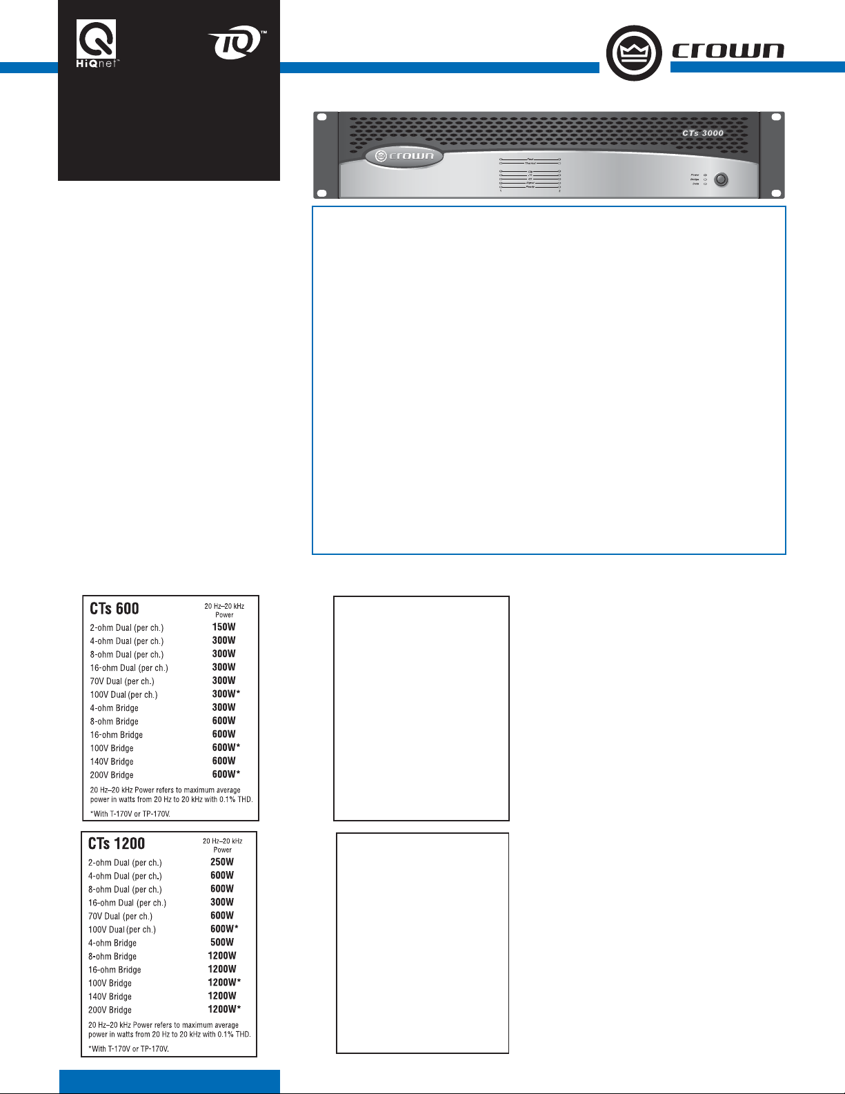
CTs Series
2-channel
CTs SERIES
uilding on the foundation of the Crown®
Com-Tech
B
fl exibility and value for installed sound appli-
®
Series, the CTs Series offers new
cations. The Com-Tech Series was the fi rst to offer
independent selection of high- and low-impedance
operation for a specifi c channel, and CTs Series
amplifi ers continue that tradition, with power
levels and features carefully chosen to perfectly
integrate into fi xed install design requirements.
For added fl exibility, the CTs Series includes both
dual-channel and multi-channel models.
All models in the CTs Series feature Crown’s new
Switching Power Supply for lighter weight, and
all models are also compatible with Harman Pro
System Architect as well as the IQ System
®
.
Two-channel models accept PIP2™ modules, and
also feature selectable high-pass fi lters and input
sensitivity for each channel.
In a profession where unplanned service calls
quickly wipe out profi ts, the CTs Series amplifi ers
are designed to be the most reliable amplifi ers you
can install.
For more details about the Crown
CTs Series,
contact Crown Customer Service at 800-342-6939
or 574-294-8200. Also, visit the Crown Audio
website at www.crownaudio.com.
Features
• Switching Power Supply for reduced weight
• High power-density, with all two-channel models in
a 2U chassis
• Direct constant-voltage (70V/100V/140V/200V) or
low-impedance (2/4/8 ohm) operation
• Input sensitivity independently selectable for each
channel
• TLC protection circuitry protects the amplifi er from
long-term excessive heat by subtly and dynamically
reducing the gain only when necessary
• PIP2 (Programmable Input Processor) connector
accepts accessory modules that tailor the amplifi er
to suit specifi c applications
• Removable terminal block input connectors, with “Y”
Input Switch in the standard PIP2-BBY module
• Switchable high-pass fi lter for each channel provides
low-frequency roll off to eliminate step down transformer saturation when used in distributed systems
• Comprehensive array of indicators including Power,
Data and Bridge, along with Ready, Signal, Clip,
Thermal and Fault for each channel, provide accurate
diagnostics
• Blue Power Indicator fl ashes if the AC mains is
under/over voltage
• Advanced protection circuitry guards against: shorted
outputs, DC, mismatched loads, general overheating,
under/over voltage, high-frequency overloads and
internal faults
• JTs circuitry (CTs 600/1200) quickly protects output
transistors from unsafe operating conditions without
shutting the channel down
• Legendary Crown AB+B (Multi-Mode
topology in the CTs 600/1200 and Class I (BCA
output topology in the CTs 2000/3000 offer the best
in amplifi er reliability
• Continuously variable fans optimize cooling effi ciency
• Three Year, No-Fault, Fully Transferable
Warranty completely protects your investment and
guarantees its specifi cations
®
) output
®
)
20 Hz–20 kHz
CTs 2000
2-ohm Dual (per ch.)
4-ohm Dual (per ch.)
8-ohm Dual (per ch.)
16-ohm Dual (per ch.)
70V Dual (per ch.)
100V Dual (per ch.)
4-ohm Bridge
8-ohm Bridge
16-ohm Bridge
140V Bridge
200V Bridge
20 Hz–20 kHz Power refers to maximum average
power in watts from 20 Hz to 20 kHz with 0.35% THD.
CTs 3000
2-ohm Dual (per ch.)
4-ohm Dual (per ch.)
8-ohm Dual (per ch.)
16-ohm Dual (per ch.)
70V Dual (per ch.)
100V Dual (per ch.)
4-ohm Bridge
8-ohm Bridge
16-ohm Bridge
140V Bridge
200V Bridge
20 Hz–20 kHz Power refers to maximum average
power in watts from 20 Hz to 20 kHz with 0.35% THD.
Power
1000W
1000W
1000W
625W
1000W
1000W
2000W
2000W
2000W
2000W
2000W
20 Hz–20 kHz
Power
1500W
1500W
1250W
625W
1500W
1500W
3000W
3000W
2500W
3000W
3000W
Specifi cations
Minimum Guaranteed Power: See power charts
at left.
Frequency Response (at 1 watt, 20 Hz - 20 kHz):
±0.25 dB.
Signal to Noise Ratio below rated power (20 Hz
to 20 kHz): 105 dB A-weighted.
Total Harmonic Distortion (THD) at full rated
power, from 20 Hz to 20 kHz: CTs 600/1200:
< 0.1%. CTs 2000/3000 < 0.35%.
Damping Factor: 10 Hz to 100 Hz: > 3000.
Crosstalk (below rated power, 20 Hz to 1 kHz):
> 80 dB.
Common Mode Rejection (CMR) (20 Hz to 1
kHz): 50 dB.
DC Output Offset: < ±2 mV.
Input Impedance (nominal): 10 kilohms balanced,
5 kilohms unbalanced.
Maximum Input Level: +20 dBu before input compression, +32 dBu absolute maximum.
Load Impedance: (Note: Safe with all types of
loads)
CTs 600/1200
Stereo: 2/4/8/16 ohms, 70V, 100V
Bridge Mono: 4/8/16 ohms, 140V.
CTs 2000/3000
Stereo: 2/4/8/16 ohms, 70V, 100V
Bridge Mono: 4/8/16 ohms, 140V, 200V.
Page 2
CTs Series
2-channel
Voltage Gain (at maximum level setting):
8/4 ohm operation, 1.4V sensitivity
CTs 600 35:1 (31 dB)
CTs 1200 50:1 (34 dB)
CTs 2000 63.9:1 (36 dB)
CTs 3000 71.4:1 (37 dB).
26 dB: 20:1 (26 dB).
70V operation, 1.4V sensitivity or 100V operation, 2.0V sensitivity: 50:1 (34 dB).
AC Line Voltage and Frequency Confi gurations
Available (±10%): 120VAC/60Hz, 230VAC/50 Hz.
Power Draw at Idle (120VAC mains):
CTs 600/1200: 24W (standby mode)
CTs 2000/3000: 35W (standby mode).
Cooling: Continuously variable speed forced air,
front-to-back airfl ow.
Dimensions: 19 in. (48.3 cm) W x 3.5 in. (8.9 cm)
H x 14.25 in. (36.2 cm) D.
Weight: Net, Shipping
CTs 600: 22.8 lb (10.3 kg), 27.7 lb (12.6 kg)
CTs 1200: 23.4 lb (10.6 kg), 28.3 lb (12.8 kg)
CTs 2000: 27.0 lb (12.2 kg), 32.0 lb (14.5 kg)
CTs 3000: 27.7 lb (12.6 kg), 32.7 lb (14.8 kg).
Front Panel Controls and Indicators
Bridge Mode Indicator: Yellow LED illuminates
when the rear-panel Mode Switch is set to the
“Bridge” position.
Ready Indicator: Green LED, one per channel,
illuminates when the channel is initialized and
ready to produce audio output. Indicator is off
when PIP puts the amplifi er in standby mode via
the control system.
Signal Indicators: Three green LEDs per channel
indicate the amplifi er’s input and output signal
levels.
Signal: input signal is above –40 dBu.
–20 dB: amplifi er output is 20 dB below clipping.
–10 dB: amplifi er output is 10 dB below clipping.
Clip Indicator: Red LED, one per channel, illuminates when the channel’s output signal reaches the
onset of audible clipping. The Clip Indicator also
will illuminate during Thermal Level Control (TLC)
limiting or when the input compressor/limiter is
protecting the amplifi er from input overload.
Thermal Indicator: Red LED, one per channel,
illuminates when the channel has shut down, or
is very near shutting down, due to thermal stress
or overload.
Fault Indicator: Red LED, one per channel, fl ashes
when the amplifi er output channel has stopped
operating.
Data Indicator: Yellow LED indicates control data
activity (if the amplifi er is equipped with an IQPIP2 module, and connected to a control system).
Power Indicator: Blue LED indicates amplifi er has
been turned on and AC power is available. The
LED will fl ash when the AC line voltage is 15%
above or 25% below the nominal rated value.
Cooling Vents: Front-to-rear forced airfl ow.
Power Switch: Push-on / push-off switch.
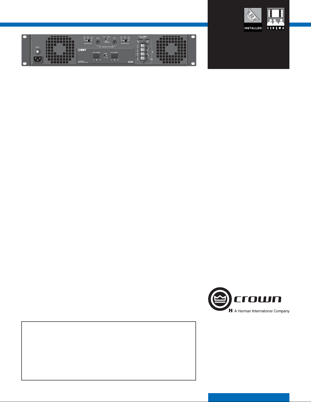
Back Panel Controls and Connectors
Power Cord Connector: Standard 15 amp IEC
inlet. Voltage is indicated above IEC inlet.
Reset Switch: Resets the circuit breaker that
protects the power supply.
Speaker Connectors: One four-pole touch-proof
terminal strip. Accepts up to 10 AWG terminal
forks.
Input Connectors: Balanced 2-pin terminal block
connector, one per channel, on the standard PIP2BBY module.
Channel Level Control: One 21-position detented
rotary attenuator per channel, ranging from minus
infi nity (–70 dB) to 0 dB gain.
Mode Switch: Two-position switch is used to
select the amplifi er’s mode of operation: Dual or
Bridge-Mono.
Highpass Filter: One 3-position switch per
channel selects between OFF, 35Hz and 70Hz
3rd-order fi lters.
“Y” Input Switch: When set to ON, this switch
parallels the input signals of the two channels for
use when the input signal is mono. Also can be
used to daisy-chain the signal to another amplifi er.
Ventilation Grille: Front-to-rear forced airfl ow.
Options
PIP2 modules, including the PIP-Lite, PIP-USP3,
and PIP-USP3/CN.
Protection Systems
Thermal Level Control (TLC): If an amplifi er chan-
nel starts to overheat, the TLC circuit will engage
the input compressor. By compressing the input,
the amplifi er will not generate as much heat and
will have a chance to cool down.
Junction Temperature Simulation (JTS): In the
CTs 600/1200, if excess power is demanded, JTS
circuitry limits the drive level of the output devices
to a safe range, preventing damage.
Fault: The amplifi er will light the Fault LED if the
amplifi er output stage stops operating.
AC Under-/Over-Voltage Protection: If the AC line
voltage drops below 25% or rises above 15% of
the nominal operating voltage of the amplifi er, the
amplifi er’s power supply turns off and the blue
Power LED fl ashes. The amplifi er will turn back on
when the AC line voltage returns to safe operating
levels.
Circuit Breaker: This breaker protects the amplifi er from excessive AC current draw.
DC Output Servo: The output servo circuit protects your drivers by eliminating DC offset, even in
the presence of very large asymmetrical signals.
In-rush Limiting: A soft-start circuit in the power
supply minimizes the amplifi er’s current draw
during power-on.
Variable-speed Fan: Two continuously variable
speed fans direct the airfl ow through the amplifi er
for cooling.
Crown’s Three-Year, No-Fault, Fully Transferable Warranty
Crown offers a Three-Year, No-Fault, Fully Transferable Warranty for every new Crown amplifi er—an
unsurpassed industry standard. With this unprecedented No-Fault protection, your new Crown
amplifi er is warranted to meet or exceed original specifi cations for the fi rst three years of ownership.
During this time, if your amplifi er fails, or does not perform to original specifi cations, it will be
repaired or replaced at our expense. About the only things not covered by this warranty are those
losses normally covered by insurance and those caused by intentional abuse. And the coverage is
transferable, should you sell your amplifi er.
See your authorized Crown dealer for full warranty disclosure and details. For customers outside
of the USA, please contact your authorized Crown distributor for warranty information or call
574-294-8200.
Crown International
1718 W. Mishawaka Rd.
Elkhart, IN 46517-9439
TEL: 574-294-8200
FAX: 574-294-8FAX
www.crownaudio.com
Specifi cations subject to change without prior notice. Latest
information available at www.crownaudio.com.
Crown, Crown Audio, Com-Tech, IQ System, BCA and MultiMode are registered trademarks and PIP2 is a trademark of
Crown International. HiQnet is a trademark of Harman International Industries, Inc. Other trademarks are the property of
their respective owners. Printed in U.S.A.
© 2007 Crown Audio
9/07 136317-2B
®
, Inc.
 Loading...