

Page 1

Operation Manual
CTs 2-Channel Series
CTs 600
CTs 1200
CTs 2000
CTs 3000
Obtaining Other Language Versions:
local Crown Distributor. If you need assistance locating your local distributor, please contact Crown at 574-294-8000.
This manual does not include all of the details of design, production, or variations of the equipment. Nor does it cover every possible
situation which may arise during installation, operation or maintenance.
The information provided in this manual was deemed accurate as of the publication date. However, updates to this information may have
occurred. To obtain the latest version of this manual, please visit the Crown website at www.crownaudio.com.
Trademark Notice:
trademarks of Crown International. Other trademarks are the property of their respective owners.
©2003 by Crown Audio, Inc. P.O. Box 1000, Elkhart, Indiana 46515-1000 U.S.A. Telephone: 574-294-8000
Com-Tech, Crown, Amcron and Multi-Mode are registered trademarks of Crown International. PIP and PIP2 are
To obtain information in another language about the use of this product, please contact your
Some models may be exported under the name Amcron.
®
134433-4
7/03
Page 2
Important Safety
Instructions
CTs 2-Channel Power Amplifiers
1) Read these instructions.
2) Keep these instructions.
3) Heed all warnings.
4) Follow all instructions.
5) Do not use this apparatus near water.
6) Clean only with a dry cloth.
7) Do not block any ventilation openings. Install
in accordance with the manufacturer’s instructions.
8) Do not install near any heat sources such as
radiators, heat registers, stoves, or other
apparatus that produce heat.
9) Do not defeat the safety purpose of the polarized or grounding-type plug. A polarized plug
has two blades with one wider than the other.
A grounding-type plug has two blades and a
third grounding prong. The wide blade or the
third prong is provided for your safety. If the
provided plug does not fit into your outlet,
consult an electrician for replacement of the
obsolete outlet.
10) Protect the power cord from being walked on
or pinched, particularly at plugs, convenience
receptacles, and the point where they exit from
the apparatus.
11) Only use attachments/accessories specified
by the manufacturer.
12) Use only with a cart, stand, bracket, or table
specified by the manufacturer, or sold with the
apparatus. When a cart is used, use caution
when moving the cart/apparatus combination
to avoid injury from tip-over.
13) Unplug this apparatus during lightning storms
or when unused for long periods of time.
14) Refer all servicing to qualified service personnel. Servicing is required when the apparatus
has been damaged in any way, such as powersupply cord or plug is damaged, liquid has
been spilled or objects have fallen into the
apparatus, the apparatus has been exposed to
rain or moisture, does not operate normally,
or has been dropped.
15) To reduce the risk of fire or electric shock, do
not expose this apparatus to rain or moisture.
TO PREVENT ELECTRIC SHOCK DO NOT REMOVE
TOP OR BOTTOM COVERS. NO USER SERVICEABLE PARTS INSIDE. REFER SERVICING TO
QUALIFIED SERVICE PERSONNEL.
À PRÉVENIR LE CHOC ÉLECTRIQUE N’ENLEVEZ
PAS LES COUVERCLES. IL N’Y A PAS DES PARTIES SERVICEABLE À L’INTÉRIEUR. TOUS REPARATIONS DOIT ETRE FAIRE PAR PERSONNEL
QUALIFIÉ SEULMENT.
IMPORTANT
CTs Series amplifiers require Class 2 output wiring.
MAGNETIC FIELD
CAUTION! Do not locate sensitive high-gain equipment such as preamplifiers or tape decks directly
above or below the unit. Because this amplifier has
a high power density, it has a strong magnetic field
which can induce hum into unshielded devices that
are located nearby. The field is strongest just above
and below the unit.
If an equipment rack is used, we recommend locating the amplifier(s) in the bottom of the rack and the
preamplifier or other sensitive equipment at the top.
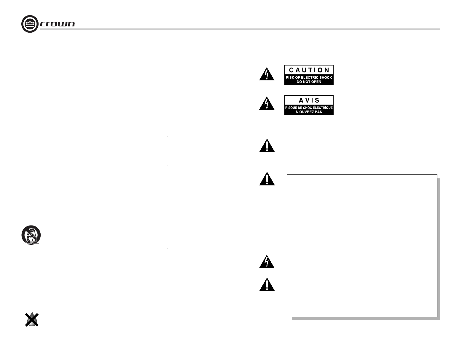
WATCH FOR THESE SYMBOLS:
The lightning bolt triangle is used to alert the user
to the risk of electric shock.
The exclamation point triangle is used to alert the
user to important operating or maintenance instructions.
FCC COMPLIANCE NOTICE
This device complies with part 15 of the FCC rules. Operation is subject to the following
two conditions: (1) This device may not cause harmful interference, and (2) this device
must accept any interference received, including interference that may cause undesired
operation.
CAUTION: Changes or modifications not expressly approved by the party responsible for
complicance could void the user’s authority to operate the euqipment.
NOTE: This equipment has been tested and found to comply with the limits for a Class B
digital device, pursuant to part 15 of the FCC Rules. These limits are designed to provide
reasonable protection against harmful interference in a residential installation. This
equipment generates, uses, and can radiate radio frequency energy and, if not installed
and used in accordance with the instruction manual, may cause harmful interference to
radio communications. However, there is no guarantee that interference will not occur in a
particular installation. If this equipment does cause harmful interference to radio or television reception, which can be determined by turning the equipment off and on, the user is
encouraged to try to correct the interference by one or more of the following measures:
• Reorient or relocate the receiving antenna.
• Increase the separation between the equipment and receiver.
• Connect the equipment into an outlet on a circuit different from that to which the
receiver is connected.
• Consult the dealer or an experienced radio/TV technician for help.
page 2
Operation Manual
Page 3

CTs 2-Channel Power Amplifiers
Crown International, Inc.
ISSUED BY: Crown International, Inc.
1718 W. Mishawaka Road
Elkhart, Indiana 46517 U.S.A.
European Representative's Name and Address:
Nick Owen
19 Clos Nant Coslech
Pontprennau
Cardiff
CF23 8ND United Kingdom
Equipment Type: Commercial Audio Power Amplifiers
Family Name: CTs
Model Names: CTs 3000, CTs 2000, CTs 1200, CTs 600
EMC Standards:
EN 55103-1:1995 Electromagnetic Compatibility - Product Family Standard for Audio, Video, Audio-Visual and Entertainment Lighting Control Apparatus for Professional Use, Part 1: Emissions
EN 55103-1:1995 Magnetic Field Emissions-Annex A @ 10 cm and 1 M
EN 61000-3-2:1995+A14:2000 Limits for Harmonic Current Emissions (equipment input current ≤16A per phase)
EN 61000-3-3:1995 Limitation of Voltage Fluctuations and Flicker in Low-Voltage Supply Systems Rated Current ≤16A
EN 55022:1992 + A1: 1995 & A2:1997 Limits and Methods of Measurement of Radio Disturbance Characteristics of ITE: Radiated, Class B Limits; Conducted, Class B
EN 55103-2:1996 Electromagnetic Compatibility - Product Family Standard for Audio, Video, Audio-Visual and Entertainment Lighting Control Apparatus for Professional Use, Part 2: Immunity
EN 61000-4-2:1995 Electrostatic Discharge Immunity (Environment E2-Criteria B, 4k V Contact, 8k V Air Discharge)
EN 61000-4-3:1996 Radiated, Radio-Frequency, Electromagnetic Immunity (Environment E2, criteria A)
EN 61000-4-4:1995 Electrical Fast Transient/Burst Immunity (Criteria B)
EN 61000-4-5:1995 Surge Immunity (Criteria B)
EN 61000-4-6:1996 Immunity to Conducted Disturbances Induced by Radio-Frequency Fields (Criteria A)
EN 61000-4-11:1994 Voltage Dips, Short Interruptions and Voltage Variation
Safety Standard:
EN 60065: 1998 Safety Requirements - Audio Video and Similar Electronic Apparatus
I certify that the product identified above conforms to the requirements of the EMC Council Directive 89/336/EEC as amended by 92/31/EEC, and the Low Voltage Directive 73/23/EES as amended by 93/68/EEC.
Signed
Larry Coburn
Title: Senior Vice President of Manufacturing
DECLARATION of CONFORMITY
Date of Issue: March 1, 2002
Sue Whitfield
574-294-8289
swhitfield@crownintl.com
Operation Manual
Due to line current harmonics, we recommend that you contact your supply authority before connection.
page 3
Page 4

Table of Contents
CTs 2-Channel Power Amplifiers
Important Safety Instructions .......................................................... 2
Declaration of Conformity .............................................................. 3
1 Welcome ...................................................... 5
1.1 Features ............................................................................. 5
2 How to Use This Manual .................................... 6
3 Setup ........................................................... 7
3.1 Unpack Your Amplifier ....................................................... 7
3.2 Install Your Amplifier ......................................................... 7
3.3 Ensure Proper Cooling ....................................................... 7
3.4 Choose Input Wire and Connectors .................................... 8
3.5 Choose Output Wire and Connectors ................................. 8
3.6 Wire Your System .............................................................. 9
3.6.1 Dual 8/4/2 Mode ....................................................... 9
3.6.2 Bridge-Mono 16/8/4 Mode........................................ 9
3.6.3 Dual 70V/100V Mode ................................................ 10
3.6.4 Bridge-Mono 140V/200V Mode ................................ 10
3.6.5 Dual Mode with “Y” Input .......................................... 11
3.7 Connect to AC Mains ......................................................... 12
3.8 Startup Procedure .............................................................. 12
4 Operation ...................................................... 12
4.1 Precautions ........................................................................12
4.2 Front Panel Controls and Indicators ...................................13
4.3 Back Panel Controls and Connectors ................................. 14
5 Advanced Features and Options ...........................15
5.1 Protection Systems ............................................................15
5.1.1 Thermal Level Control (TLC) .....................................15
5.1.2 Junction Temperature Simulation (JTS) .....................15
5.1.3 Fault ..........................................................................15
5.1.4 High-Pass Filters ......................................................15
5.1.5 Low-Pass Filters .......................................................15
5.1.6 AC Under/Over Voltage Protection ............................15
5.1.7 Circuit Breaker ..........................................................15
5.1.8 DC Output Servo .......................................................15
5.1.9 Inrush Limiting ..........................................................15
5.1.10 Variable-speed Fans ................................................15
5.2 Advanced Features .............................................................15
5.2.1 Switching Power Supply ...........................................15
5.2.2 Input Compressor .....................................................15
5.2.3 Sleep Circuit..............................................................15
5.2.4 Input Sensitivity Switches .........................................16
5.3 Options ..............................................................................16
5.3.1 Nominal Attenuation Settings ....................................17
6 Troubleshooting ...............................................18
7 Specifications .................................................20
8 Service .........................................................24
8.1 Worldwide Service .............................................................24
8.2 US and Canada Service.......................................................24
8.2.1 Service at a US or Canada Service Center .................24
8.2.2 Factory Service .........................................................24
8.2.3 Factory Service Shipping Instructions .......................24
8.2.4 Crown’s Profit Protection Plan ...................................24
9 Warranty........................................................25
Crown Factory Service Information Form .......................................27
page 4
Operation Manual
Page 5
CTs 2-Channel Power Amplifiers
20 Hz–20 kHz
*
CTs 600
2-ohm Dual (per ch.)
4-ohm Dual (per ch.)
8-ohm Dual (per ch.)
16-ohm Dual (per ch.)
70V Dual (per ch.)
4-ohm Bridge
8-ohm Bridge
16-ohm Bridge
140V Bridge
*20 Hz–20 kHz Power: refers to maximum
average power in watts from 20 Hz
to 20 kHz with 0.1% THD.
CTs 1200
2-ohm Dual (per ch.)
4-ohm Dual (per ch.)
8-ohm Dual (per ch.)
16-ohm Dual (per ch.)
70V Dual (per ch.)
4-ohm Bridge
8-ohm Bridge
16-ohm Bridge
140V Bridge
*20 Hz–20 kHz Power: refers to maximum
average power in watts from 20 Hz
to 20 kHz with 0.1% THD.
Power
150W
300W
300W
300W
300W
300W
600W
600W
600W
20 Hz–20 kHz
*
Power
250W
600W
600W
300W
600W
500W
1200W
1200W
1200W
1 Welcome
Building on the foundation of the Com-Tech®
Series, the Crown
bility and value for installed sound. The ComTech Series was the first to offer independent
selection of high- and low-impedance operation for a specific channel, and CTs Series
amplifiers continue that tradition, with power
levels and features carefully chosen to perfectly
integrate into fixed install design requirements.
Modern power amplifiers are sophisticated
pieces of engineering capable of producing
extremely high power levels. They must be
treated with respect and correctly installed if
they are to provide the many years of reliable
service for which they were designed.
In addition, CTs Series amplifiers include a
number of features which require some explanation before they can be used to their maximum advantage.
Please take the time to study this manual so
that you can obtain the best possible service
from your amplifier.
1.1 Features
• Switching Power Supply for reduced
weight.
• High power-density, with all two-channel
models in a 2U chassis.
®
CTs Series offers new flexi-
• Direct constant-voltage
(70V/100V/140V/200V) or low-impedance
(2/4/8 ohm) operation. No switch
required.
• Input sensitivity is independently selectable for each channel. Choose low-impedance (4/8 ohm), constant-voltage (70V/
100V/140V/200V), or 26 dB.
• TLC protection circuitry protects the
amplifier from long-term excessive heat by
subtly and dynamically reducing the gain
only when necessary.
• JTS circuitry (CTs 600/1200 only) quickly
protects BJT output transistors from
unsafe operating conditions without shutting the channel down. (Not applicable to
BCA amplifiers as they are inherently protected.)
• PIP2™ (Programmable Input Processor)
connector accepts accessory modules that
tailor the amplifier to suit specific applications.
• Removable terminal block input connectors, with “Y” Input Switch in the standard
PIP2-BBY module.
(Continued on next page)
20 Hz–20 kHz
*
CTs 2000
2-ohm Dual (per ch.)
4-ohm Dual (per ch.)
8-ohm Dual (per ch.)
16-ohm Dual (per ch.)
70V Dual (per ch.)
100V Dual (per ch.)
4-ohm Bridge
8-ohm Bridge
16-ohm Bridge
140V Bridge
200V Bridge
*20 Hz–20 kHz Power: refers to maximum
average power in watts from 20 Hz
to 20 kHz with 0.35% THD.
CTs 3000
2-ohm Dual (per ch.)
4-ohm Dual (per ch.)
8-ohm Dual (per ch.)
16-ohm Dual (per ch.)
70V Dual (per ch.)
100V Dual (per ch.)
4-ohm Bridge
8-ohm Bridge
16-ohm Bridge
100V Bridge
200V Bridge
*20 Hz–20 kHz Power: refers to maximum
average power in watts from 20 Hz
to 20 kHz with 0.35% THD.
Power
1000W
1000W
1000W
625W
1000W
1000W
2000W
2000W
2000W
2000W
2000W
20 Hz–20 kHz
*
Power
1500W
1500W
1250W
625W
1500W
1500W
3000W
3000W
2500W
3000W
3000W
Operation Manual
page 5
Page 6

1 Welcome
CTs 2-Channel Power Amplifiers
Features (continued from page 4)
• Switchable high-pass filter for each channel provides low-frequency roll off to eliminate step down transformer saturation
when used in distributed systems.
• Comprehensive array of indicators including Power, Data, and Bridge; along with
Ready, Signal, Clip, Thermal and Fault for
each channel, provide accurate diagnostics.
• Blue Power Indicator flashes if the amplifier shuts off due to an under/over-voltage
condition on the AC mains.
• Advanced protection circuitry guards
against: shorted outputs, DC, mismatched
loads, general overheating, under-/overvoltage, high-frequency overloads and
internal faults.
• Legendary Crown class I (BCA) and class
AB+B (Multi-Mode
offer the best in amplifier reliability. CTs
600/1200 use Class AB+B; CTs 2000/
3000 use Class I.
• Class I is the lowest distortion, lowest
noise, and highest performing topology
available among switch-mode amplifiers.
• Continuously-variable fans optimize cooling efficiency.
• Three Year, No-Fault, Fully-Transferable
Warranty completely protects your investment and guarantees its specifications.
• Crown’s Profit Protection Plan guarantees
replacement of covered amps should they
fail at any time during the original threeyear warranty period (available in U.S.
only).
®
) output topologies
2 How to Use This
Manual
This manual provides you with the necessary
information to safely and correctly setup and
operate your amplifier. It does not cover every
aspect of installation, setup or operation that
might occur under every condition. For additional information, please consult Crown’s
Amplifier Application Guide (available online at
www.crownaudio.com), Crown Tech Support,
your system installer or retailer.
We strongly recommend you read all instructions, warnings and cautions contained in this
manual. Also, for your protection, please send
in your warranty registration card today. And
save your bill of sale—it’s your official proof of
purchase.
page 6
Operation Manual
Page 7
CTs 2-Channel Power Amplifiers
3 Setup
3.1 Unpack Your Amplifier
Please unpack and inspect your amplifier for
any damage that may have occurred during
transit. If damage is found, notify the transportation company immediately. Only you can initiate a claim for shipping damage. Crown will
be happy to help as needed. Save the shipping
carton as evidence of damage for the shipper’s
inspection.
We also recommend that you save all packing
materials so you will have them if you ever
need to transport the unit. Never ship the
unit without the factory pack.
YOU WILL NEED (not supplied):
• Input wiring cables
• Output wiring cables
Rack for mounting amplifier (or a stable surface
for stacking)
WARNING: Before you start to set up
your amplifier, make sure you read and
observe the Important Safety Instructions found at the beginning of this
manual.
3.2 Install Your Amplifier
CAUTION: Before you begin, make sure
your amplifier is disconnected from the
power source, with power switch in the
“off” position and all level controls
turned completely down (counterclockwise).
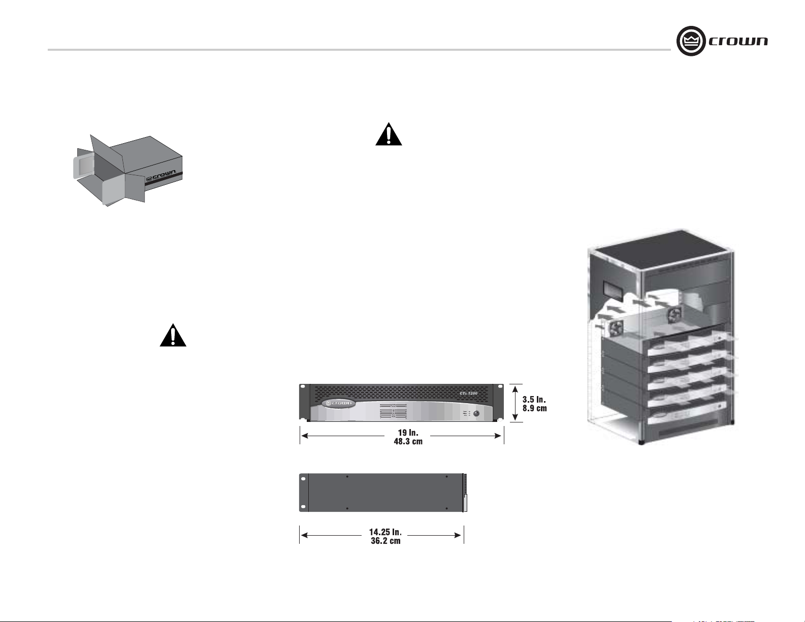
Use a standard 19-inch (48.3 cm) equipment
rack. See Figure 3.1 for amplifier dimensions.
You may also stack amps without using a cabinet.
NOTE: When transporting, amplifiers should be
supported at both front and back.
3.3 Ensure Proper Cooling
When using an equipment rack, mount units
directly on top of each other. Close any open
spaces in rack with blank panels. DO NOT
block front or rear air vents. The side walls of
the rack should be a minimum of two inches
(5.1 cm) away from the amplifier sides, and the
back of the rack should be a minimum of four
inches (10.2 cm) from the amplifier back panel.
Figure 3.2 illustrates standard amplifier airflow.
Operation Manual
Figure 3.2 Airflow
FRONT
Figure 3.1 CTS 2-Channel Series Dimensions
page 7
Page 8
3 Setup
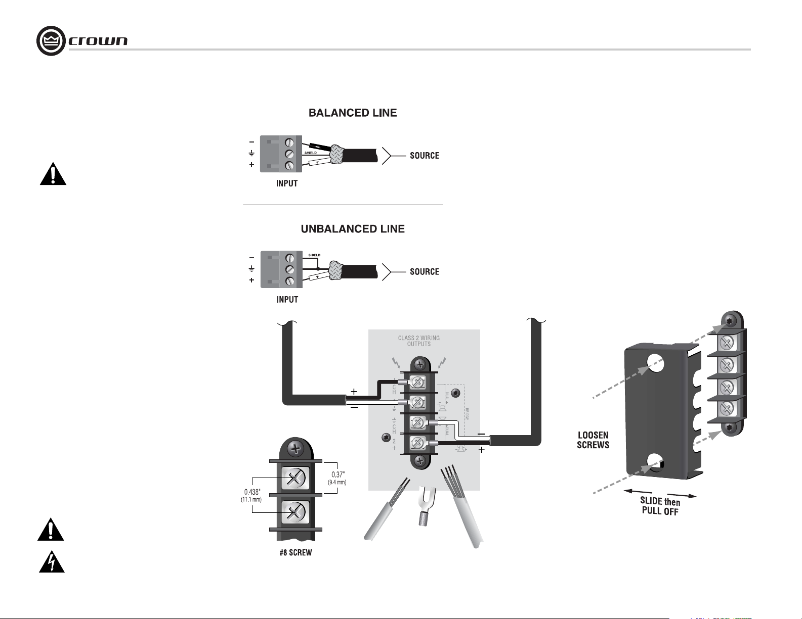
3.4 Choose Input Wire
and Connectors
Figure 3.3 shows connector pin assignments for
balanced wiring, and Figure 3.4 shows connector pin assignments for unbalanced wiring.
NOTE: Custom wiring should only be performed by qualified personnel.
3.5 Choose Output Wire and Connectors
A protective cover is installed over the barrierstrip output. Some models have a cover with two
holes. To remove this type of cover:
1. Loosen screws inside top and bottom holes of
cover (see Figure 3.6).
2. Slide cover to left or right, then pull it off away
from the amplifier.
Crown recommends using professionally constructed, high-quality, two- or four-conductor,
heavy gauge speaker wire and connectors. You
may use terminal forks up to 10 AWG or bare
wire for your output connectors (see Figure 3.5).
To prevent the possibility of short-circuits, wrap
or otherwise insulate exposed loudspeaker cable
connectors. For best results, Crown recommends Panduit part #PV10-10LF-L or equivalent
terminal fork. Screw spacing is shown in Figure
3.5.
Using the guidelines below, select the appropri-
ate size of wire based on the distance from
amplifier to speaker (low-impedance loads only).
Distance Wire Size
up to 25 ft. (7.6m) 16 AWG
26-40 ft. (7.9-12.2m) 14 AWG
41-60 ft. (12.5-18.3m) 12 AWG
> 60 ft (18.3m) 10 AWG
CTs 2-Channel Power Amplifiers
Figure 3.3
Balanced Input
Connector Wiring
Figure 3.4
Unbalanced Input
Connector Wiring
page 8
CAUTION: Never use shielded cable for
output wiring.
Replace output cover after output wiring
is complete.
Figure 3.6 How to Remove the Two-Holed
Barrier-Block Cover
Figure 3.5 Typical Output Connector Wiring
Operation Manual
Page 9
CTs 2-Channel Power Amplifiers
3 Setup
3.6 Wire Your System
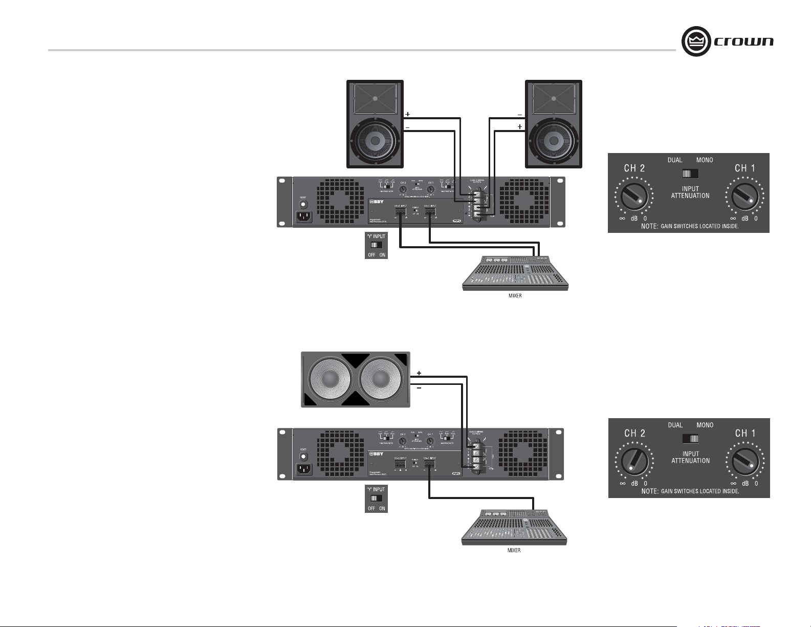
3.6.1 Dual 8/4/2 Mode
Typical input and output wiring, along with Attenuator
and Mode Switch settings are shown in Figures 3.6 and
3.7. Make sure the Mode switch is set to the “Dual” position when operating in Dual mode.
INPUTS: Connect input wiring for each channel. The Y
switch on the rear PIP panel can be used to parallel the
channel inputs when only mono input signals are necessary. The amplifier’s channel outputs are still independent.
OUTPUTS: Maintain proper polarity (+/–) on
output connectors.
Connect the Channel 1 speaker’s positive (+) lead to
amplifier Channel 1 positive terminal; repeat for negative
(–). Repeat Channel-2 wiring as for Channel 1. Refer to
Section 3.5 for output connector pin assignments.
3.6.2 Bridge-Mono 16/8/4 Mode
Typical input and output wiring, along with Attenuator
and Mode Switch settings, are shown in Figures 3.8 and
3.9. Make sure the Mode switch is set to the “Mono”
position when operating in Bridge-Mono mode.
INPUTS: Connect input wiring to Channel 1 only.
OUTPUTS: Connect the speaker across the positive ter-
minals of each channel pair. Do not use the negative terminals of the channel pair when the pair is being
operated in Bridge-Mono mode. Refer to Section 3.5 for
output connector pin assignments.
NOTE: Crown provides a reference of wiring pin assignments for commonly used connector types in the Crown
Amplifier Application Guide available at
www.crownaudio.com.
NOTE: When operating in Bridge-Mono mode,
turn down (full CCW) the Input Attenuator for
Channel 2. The Channel-1 Input Atttenuator
works both channels.
See the next page for constant-voltage operation.
Figure 3.8 Attenuator and Mode-
Switch Settings for Dual Mode
Figure 3.7 System Wiring, Dual Mode.
Always route the input and output wires in
separate bundles.
Figure 3.10 Attenuator and Mode-
Switch Settings for Bridge-Mono Mode
Operation Manual
Figure 3.9 System Wiring, Bridge-Mono Mode
page 9
Page 10
3 Setup
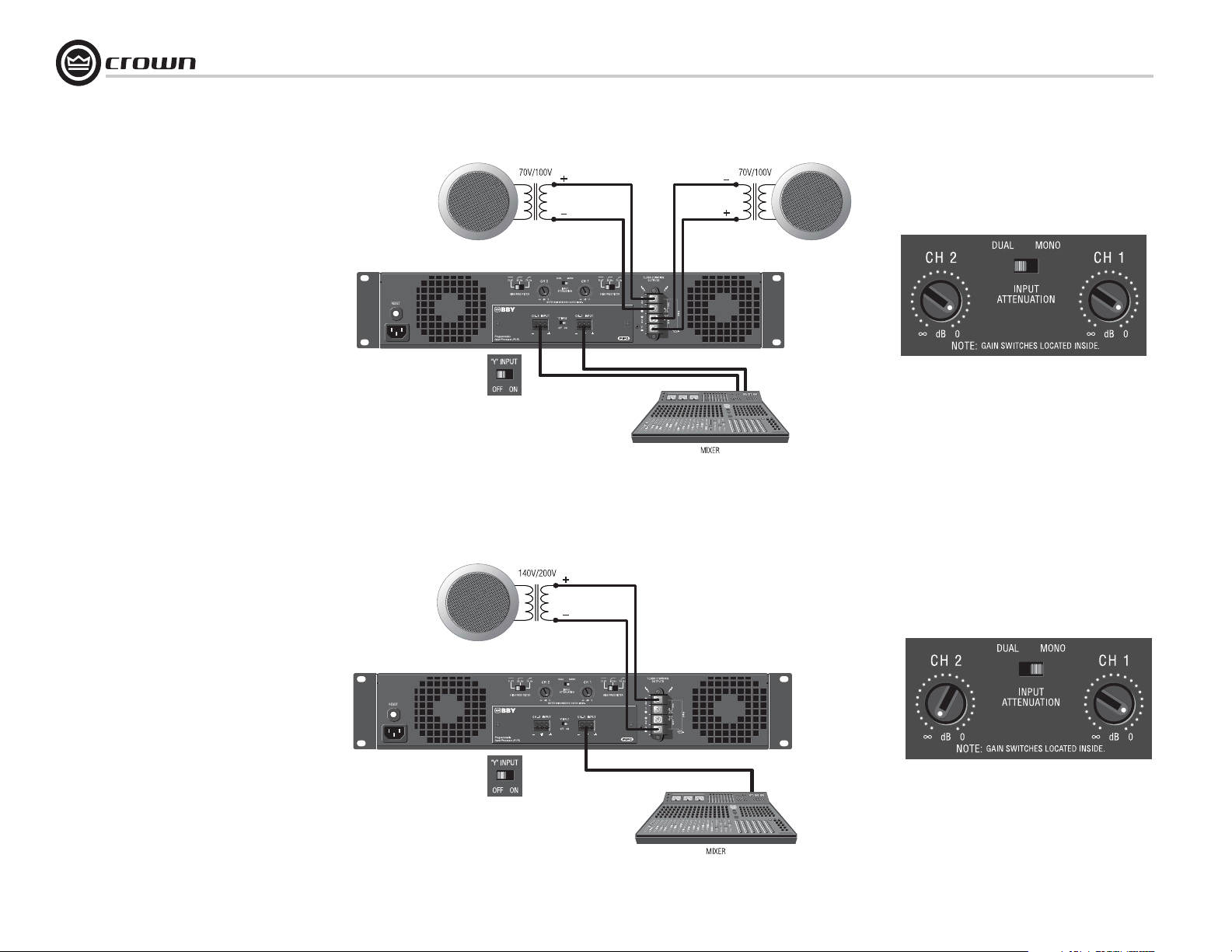
3.6.3 Dual 70V/100V Mode
Typical input and output wiring, along with Attenuator and Mode Switch settings are shown in Figures 3.10 and 3.11. Make sure the Mode switch is
set to the “Dual” position when operating in Dual
mode.
INPUTS: Connect input wiring to both channels.
OUTPUTS: In Dual Mode, the CTs 600/1200 can
power 25/50/70V lines; the CTs 2000/3000 can
power 25/50/70/100V lines. Connect each channel of output connectors to speakers that have the
appropriate transformers.
.
CTs 2-Channel Power Amplifiers
Figure 3.12 Attenuator and Mode-Switch
Settings for 70V/100V Operation
3.6.4 Bridge-Mono 140V/200V Mode
Typical input and output wiring, along with Attenuator and Mode Switch settings are shown in Figures 3.12 and 3.13. Make sure the Mode switch is
set to the “Mono” position when operating in
Bridge-Mono mode.
INPUTS: Connect input wiring to Channel 1 only.
OUTPUTS: In Bridge-Mono mode, the CTs 600/
1200 can power 140V lines; the CTs 2000/3000
can power 140V and 200V lines. Connect speakers with 140V or 200V transformers across the
positive terminals of the channel pair. Do not use
the negative terminals of the channel pair when
the pair is being operated in Bridge-Mono mode.
Refer to Section 3.5 for output connector pin
assignments.
NOTE: When operating in Bridge-Mono
mode, turn down (full CCW) the Input
Attenuator for Channel 2. The Channel-1
Input Attenuator works both channels.
page 10
Figure 3.11 System Wiring and Y-Switch Setting for 70V/100V Operation
Figure 3.13 System Wiring and Y-Switch Setting for 140V/200V Operation
Always route the input and output wires in
separate bundles.
Figure 3.14 Attenuator and Mode-Switch
Settings for 140V/200V Operation
Operation Manual
Page 11
CTs 2-Channel Power Amplifiers
3 Setup
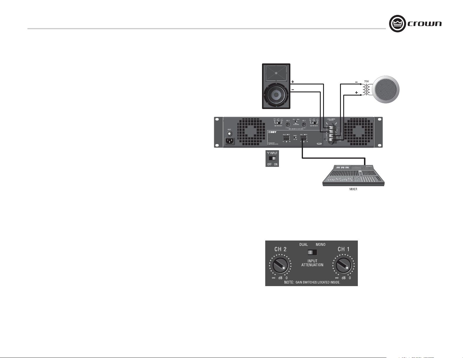
3.6.5 Dual Mode with “Y” Input
See Figure 3.14. This configuration feeds a mono
signal to both Channel 1 and Channel 2. In the
example in Figure 3.14, Channel 1 is driving a lowimpedance loudspeaker and Channel 2 is driving a
loudspeaker with a 70V transformer.
INPUTS:
Connect the signal to the Channel 1 input. On the
back panel, set the “Y” Input Switch to ON.
OUTPUTS:
Connect the Channel 1 speaker’s positive (+) lead
to Channel 1 positive terminal of amp; repeat for
negative (–).
Connect the Channel 2 speaker’s positive (+) lead
to Channel 2 positive terminal of amp; repeat for
negative (–).
See Figure 3.15. Turn up both Input Attenuators and
set the Mode Switch to Dual.
NOTE: When the “Y” Input Switch is on, the Channel 2 input can be used to daisy-chain to another
amplifier.
Figure 3.15 System Wiring for “Y” Input Mode
Operation Manual
Always route the input and output wires in
separate bundles.
Figure 3.16
Attenuator and Mode-Switch
Settings for “Y” Input Mode
page 11
Page 12

3 Setup
CTs 2-Channel Power Amplifiers
page 12
3.7 Connect to AC Mains
On the back panel, check whether your amplifier is labeled
for 120V or 220-240V AC mains. Connect your amplifier
to the corresponding AC mains power source (power outlet) with the supplied AC power cordset. First, connect the
IEC end of the cordset to the IEC connector on the amplifier. Then, with the amplifier in the OFF position, plug the
other end of the cordset into the AC mains.
WARNING: The third prong of this connector
(ground) is an important safety feature. Do not
attempt to disable this ground connection by
using an adapter or other methods.
Amplifiers don’t create energy. The AC mains voltage and
current must be sufficient to deliver the power you expect.
Check the amplifier’s back-panel label which specifies the
required AC mains voltage and frequency. The AC mains
voltage must be no more than 15% above the required
voltage, and no less than 25% below the required voltage.
The AC mains frequency must be within the required frequency range. If you are unsure of the output voltage of
your AC mains, please consult your electrician.
3.8 Startup Procedure
Use the following procedure when first turning on your
amplifier:
1. Turn down the level of your audio source.
2. Turn down the level controls of the amplifier.
3. Turn on the “Power” switch. The Power indicator
should glow. Wait for the “Ready” LED to illuminate.
4. Turn up the level of your audio source to an optimum
level.
5. Turn up the Level controls on the amplifier until the
desired loudness or power level is achieved. Verify
that the Signal LED is flashing.
6. Turn down the level of your audio source to its normal
range.
If you ever need to make any wiring or installation
changes, don’t forget to turn off the amplifier and disconnect the power cord.
For help with determining your system’s optimum gain
structure (signal levels) please refer to the Crown Ampli-
fier Application Guide, available online at
www.crownaudio.com.
4 Operation
4.1 Precautions
Your amplifier is protected from internal and external
faults, but you should still take the following precautions
for optimum performance and safety:
1. Before use, your amplifier first must be configured for
proper operation, including input and output wiring
hookup. Improper wiring can result in serious operating difficulties. For information on wiring and configuration, please consult the Setup section of this
manual or, for advanced setup techniques, consult
Crown’s Amplifier Application Guide available online
at www.crownaudio.com.
2. Use care when making connections, selecting signal
sources and controlling the output level. The load you
save may be your own!
3. Do not short the ground lead of an output cable to the
input signal ground. This may form a ground loop
and cause oscillations.
4. Never connect the output to a power supply,
battery or power main. Electrical shock may
result.
5. Tampering with the circuitry, or making unauthorized
circuit changes may be hazardous and invalidates all
agency listings.
6. Do not operate the amplifier with the red Clip LEDs
constantly flashing.
7. Do not overdrive the mixer, which will cause clipped
signal to be sent to the amplifier. Such signals will be
reproduced with extreme accuracy, and loudspeaker
damage may result.
8. Do not operate the amplifier with less than the rated
load impedance. Due to the amplifier’s output protection, such a configuration may result in premature
clipping and speaker damage.
Remember: Crown is not liable for damage that results
from overdriving other system components.
Operation Manual
Page 13
CTs 2-Channel Power Amplifiers
4 Operation
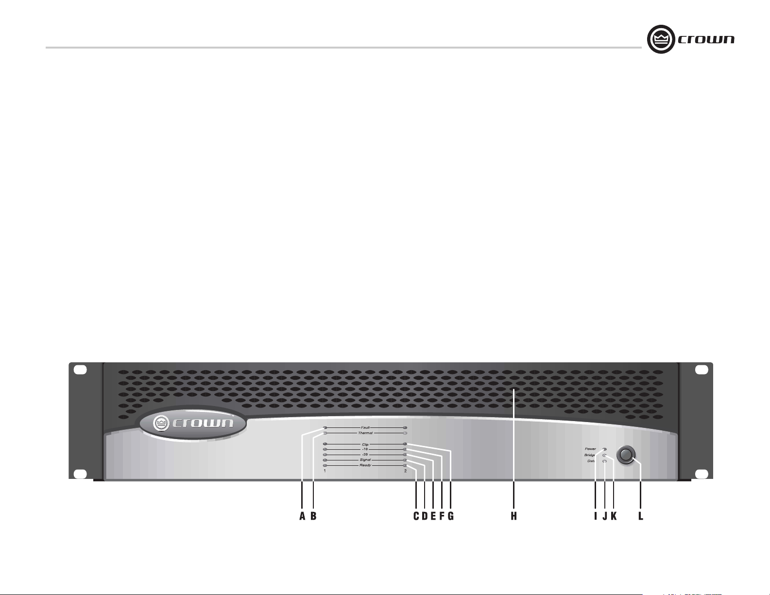
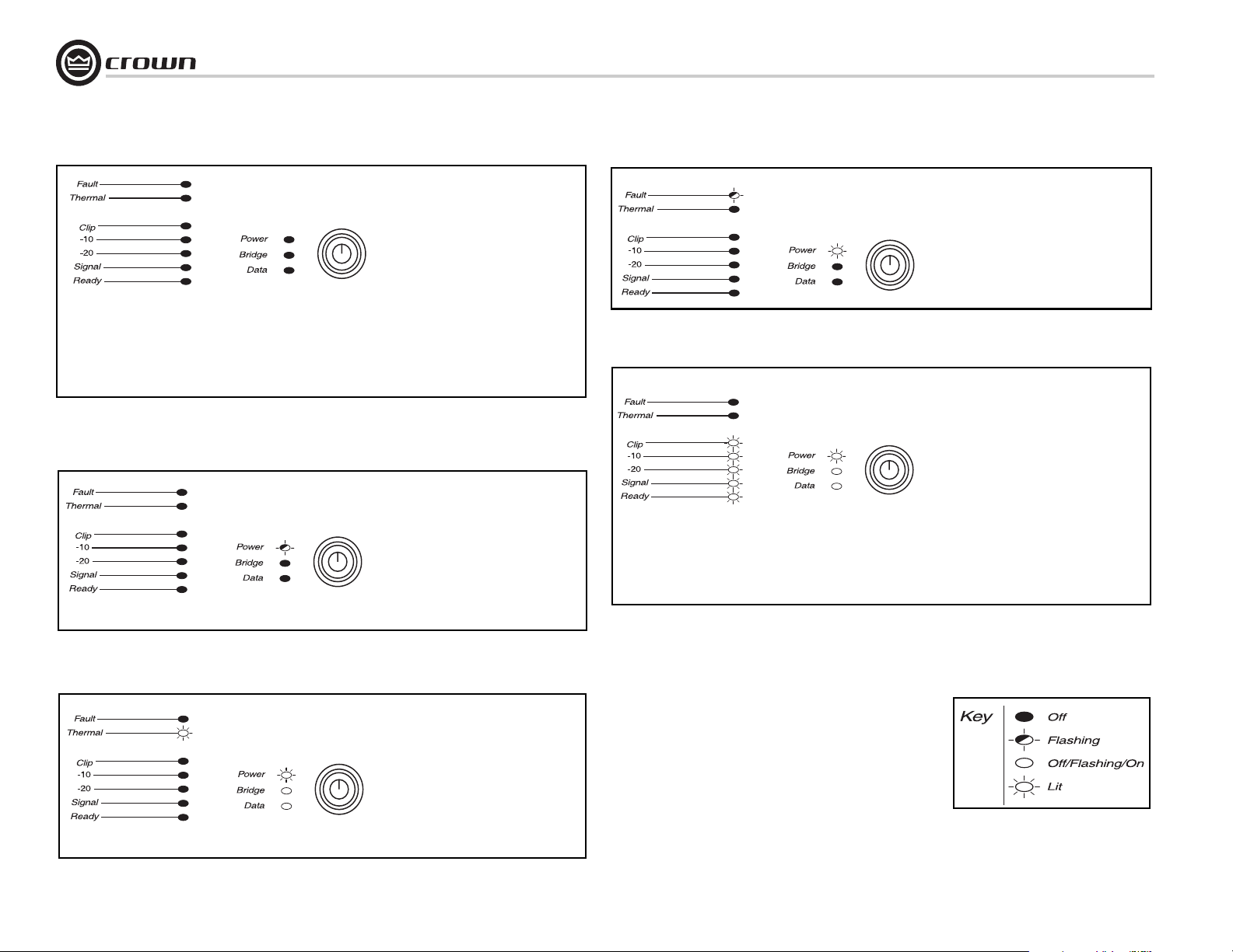
4.2 Front Panel Controls
and Indicators
A. Fault Indicator
Red LED, one per channel, flashes when
the amplifier output channel has stopped
operating. Usually this means that the
amplifier must be serviced.
B. Thermal Indicator
Red LED, one per channel, illuminates
when the channel has shut down, or is
very near shutting down, due to thermal
stress or overload.
C. Ready Indicator
Green LED, one per channel, illuminates
when the channel is initialized and ready to
produce audio output. Indicator is off when
the channel is set to standby mode via the
IQ system.
Signal Indicators
Three green LEDS per channel indicate the
amplifier’s input and output signal levels.
From bottom to top the LEDs are:
D. Signal: input signal is above –40 dBu.
E. –20 dB: amplifier output is within 20 dB of
clipping.
F. –10 dB: amplifier output is within 10 dB of
clipping.
G. Clip Indicator
Red LED, one per channel, illuminates
when the channel’s output signal reaches
the onset of audible clipping. The Clip
Indicator also will illuminate during Thermal Level Control (TLC) limiting or when
the input compressor/limiter is protecting
the amplifier from input overload.
H. Cooling Vents
Front-to-rear forced airflow.
I. Power Indicator
Blue LED indicates AC power has been
applied and is within the safe operating
range of the power supply. The LED will
flash when the AC line voltage is approximately 15% above or 25% below the nominal rated value.
J. Data Indicator
Yellow LED indicates IQ Loop data activity
This LED is driven by the IQ-PIP2 module
via the PIP2
flashes only when the installed PIP module
is polled for data, or is polled to see
whether it is online.
K. Bridge Mode Indicator
Yellow LED illuminates when the rearpanel Mode Switch is set to the “Bridge”
position
L. Power Switch
Push-on / push-off switch.
interface. Note: Data indicator
Operation Manual
Figure 4.1 CTs 600 front panel.
page 13
Page 14
4 Operation
CTs 2-Channel Power Amplifiers
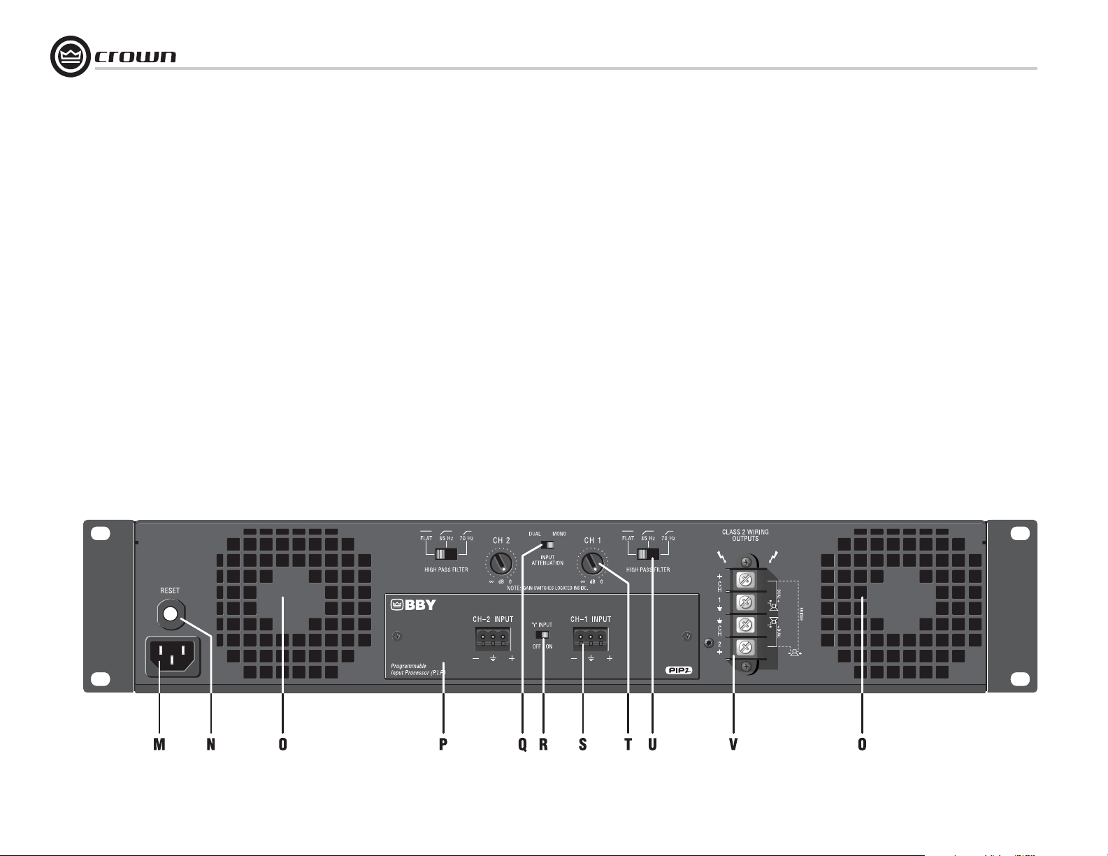
4.3 Back Panel Controls
and Connectors.
CTs 2000/3000 back panel is shown.
CTs 600/1200 look slightly different near
the Reset button.
M. Power Cord Connector
Standard 15 amp IEC inlet. A circuit
breaker located near the IEC power inlet
protects the amplifier from excessive AC
current draw.
N. Reset Switch
Resets the circuit breaker that protects the
power supply.
O. Ventilation Grille
Air flow is front to back. Do not block the
ventilation grilles.
P. PIP ™ Input Panel
PIP2-BBY module includes two balanced
3-pin removable barrier connectors. The
“Y” Input Switch is described under
letter R.
Sensitivity Switches
Behind the input panel are the Input Sensitivity Switches. One 3-position switch per
channel selects various sensitivity settings. See Section 5.2.4 for details and
diagram.
Q. Mode Switch
This two-position switch is used to select
the amplifier’s mode of operation: Dual or
Bridge Mono.
Dual mode is used for 2/4/8 ohms, for 70V
operation with the CTs 600/1200, and for
70/100V operation with the CTs 2000/
3000.
Bridge mode is used for 4/8/16 ohms, for
140V operation with the CTs 600/1200,
and for 100/140/200V operation with the
CTs 2000/3000.
R. “Y” Input Switch
When set to ON, this switch parallels the
input signals of the two channels, for use
when the input signal is mono. The amplifier’s channel outputs are still independent.
The “Y” Input Switch also can be used to
daisy-chain the signal to another amplifier.
See Section 3.6.5 for details.
S. Input Connectors
Balanced 3-pin terminal block connectors,
one per channel.
T. Channel Level Controls
One 21-position detented rotary attenuator
per channel, ranging from –100 dB to 0 dB
gain.
U. High-Pass Filter
One 3-position switch per channel selects
between OFF, 35Hz and 70Hz 3rd-order filters.
V. Speaker Connectors
One four-pole touch-proof terminal strip.
Accepts up to 10 AWG terminal forks.
Output Cover (not shown)
This covers the output connectors, protecting users from the connectors’ potentially high voltage. This cover is required
for Class 2 wiring installations. See Section 3.5 for details on removing covers that
have two holes.
page 14
Figure 4.2 CTs 2000 and 3000 Back Panel Controls and Connectors
Operation Manual
Page 15

CTs 2-Channel Power Amplifiers
5 Advanced Features
and Options
NOTE: For detailed information about
these Crown amplifier features, please
consult the Crown Amplifier Application
Guide, available on the Crown website
at www.crownaudio.com
5.1 Protection Systems
Your Crown amplifier provides extensive protection and diagnostic capabilities, including
thermal level control, fault indicators, highpass filtering, DC protect, AC under/over voltage protection, inrush limiting, and variablespeed fans.
5.1.1 Thermal Level Control (TLC)
If the amplifier becomes too hot for safe operation, the light will shine brightly and TLC will
engage the input compressor. By compressing
the input, the amplifier will not generate as
much heat and will have a chance to cool down.
The degree of compression is proportional to
the amount of overheating. This feature allows
the show to go on, rather than having the
amplifier shut down.
5.1.2 Junction Temperature Simulation (JTS) (CTs 600/1200 only)
JTS circuitry simulates the operation of the
amplifier’s output transistors, and compares it
against the transistors known Safe Operation
Area (SOA). If JTS sees that more power is
about to be asked of the output devices than
they are capable of delivering under the present
conditions, JTS immediately limits the drive
level until it falls within the SOA. Limiting is
proportional and kept to an absolute minimumonly what is required to prevent the possibility
of output transistor damage.
This level of protection enables Crown to
increase output transistor utilization while also
greatly increasing amplifier reliability.
5.1.3 Fault
The amplifier will light the Fault LED if the
amplifier output stage stops operating. If this
happens, see Section 8 for servicing information.
5.1.4 High-Pass Filters
Very low frequency signals contain no useful
musical energy, waste valuable amplifier power
and headroom, and can be damaging to your
speakers. Your Crown amplifier provides highpass filters to remove these signals from each
channel’s output.
On the back panel are two 3-position 3rd-order
high-pass filter switches (one per channel) with
selections of Off, 35Hz and 70 Hz.
5.1.5 Low-Pass Filters
Gaussian-approximation ultrasonic filters prevent ultrasonic feedback and HF burnout in
drivers. This type of filter preserves transient
reponse better than a Butterworth filter.
5.1.6 AC Under/Over Voltage
Protection
If the AC line voltage drops below 25% or rises
above 15% of the nominal operating voltage of
the amplifier, the amplifier’s power supply turns
off and the blue Power LED flashes. The amplifier will turn back on when the AC line voltage
returns to safe operating levels (within +15% /
-25%).
5.1.7 Circuit Breaker
A circuit breaker located near the IEC power
inlet protects the amplifier from excessive AC
current draw.
5.1.8 DC Output Servo
The output servo circuit protects your drivers
by eliminating DC offset, even in the presence
of very large asymmetrical signals.
5.1.9 Inrush Limiting
A soft-start circuit in the power supply minimizes the amplifier’s current draw during
power-on.
5.1.10 Variable-speed Fans
Two continuously variable speed fans direct the
airflow through the amplifier for cooling.
5.2 Advanced Features
5.2.1 Switching Power Supply
Crown’s Switching Power Supply minimizes
the amplifier’s weight.
Typical non-switching power supplies require
large, heavy transformers in order to produce
the required power at the output stage. These
transformers must be large to operate at 50 to
60 Hz (standard AC supplied by the power
company).
By contrast, switching power supplies can
operate with a much smaller (and lighter) transformer because they first convert the AC up to a
much higher frequency, thereby reducing
waste.
The power supply is voltage-specific, allowing
use in regions using 120V or 240V.
5.2.2 Input Compressor
Prevent input/output overload.
5.2.3 Sleep Circuit
Lowers standby power consumption by shutting down the high-voltage supplies during idle
periods.
NOTE: By default, the sleep circuit is not active
on the CTs 600/1200, but may be activated as a
service option.
Operation Manual
page 15
Page 16
5 Advanced Features
and Options
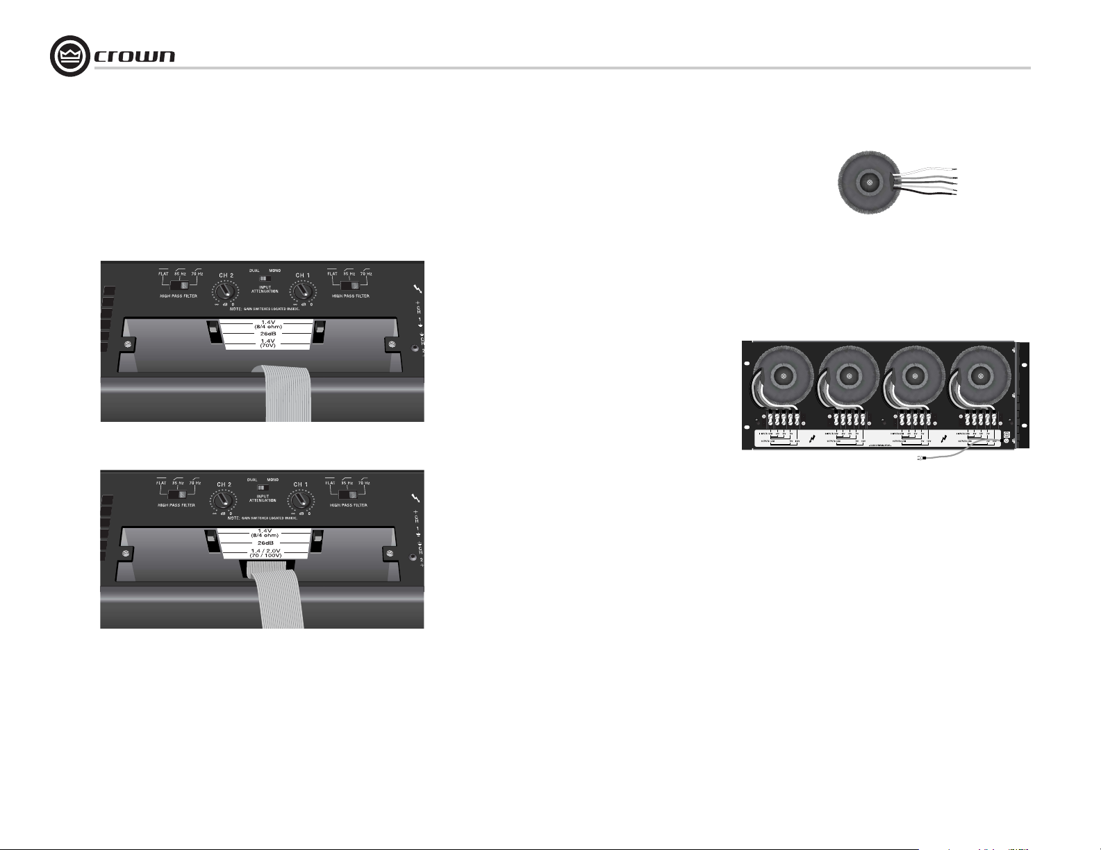
5.2.4 Input Sensitivity Switches
To access the Input Sensitivity Switches, turn off the amplifier and remove the
PIP2-BBY Input Panel. The switches are in the top surface of the cavity behind the
Input Panel. One 3-position switch per channel selects among these settings: CTs
600/1200: 1.4V (8/4 ohms), 26 dB gain, and 1.4V (70V operation). CTs 2000/
3000: 1.4V (8/4 ohms), 26 dB gain, and 1.4V (70V) / 2V (100V). The Specifications
chapter lists the input sensitivity for the 26 dB gain setting.
Figure 5.1 Input Sensitivity Switches for CTs 600/1200
5.3 Options
T-170V: See Figure 5.3. This is an autoformer that
allows 100V output from the CTs 600/1200, and
allows other amplifiers without direct constant voltage
output to be easily integrated into distributed systems.
TP-170V: See Figure 5.4. This is a rack-mountable
panel with four autoformers as described above.
PIP Modules
Versatile PIP (Programmable Input Processor) modules provide flexible expansion features that can be
added to customize the amplifier. PIP modules plug
into the connector inside the back panel of the amplifier. PIP modules are available with features ranging
from error-driven compressor/limiters to crossovers to
IQ control. Your amplifier is a PIP2 amplifier, which
means it can take advantage of the many advanced features found in PIP2 modules. The CTs Series 2-channel models do not accept earlier PIP
Visit the Crown website at www.crownaudio.com, or
contact Crown Customer Service, for descriptions of
available PIP and PIP2 modules.
modules.
CTs 2-Channel Power Amplifiers
Figure 5.3 170V
page 16
Figure 5.4 TP-170V (back view)
Figure 5.2 Input Sensitivity Switches for CTs 2000/3000
Operation Manual
Page 17

CTs 2-Channel Power Amplifiers
5 Advanced Features
and Options
5.3.1 Nominal Attenuation Settings
The signal level for each input can be attenuated accurately by
adjusting the 21-step Level Control (see Section 4.3). Figure 5.5
shows the attenuation in dB for each detent. The setting of the
input-sensitivity switch varies the actual attenation as shown.
The accuracy of the attenuation varies with the setting. Expected
tolerances are:
Potentiometer steps 0-6 dB: ± 1 dB
Potentiometer steps 6-12 dB: ± 1.5 dB
Potentiometer steps 12-24 dB: ± 3 dB
Potentiometer steps 24-54 dB: ± 6 dB
Detent 26 dB 4/8 ohm or 70/100V
0 (full CW) 0.0 0.0
10.5 0.5
21.0 1.5
32.0 3.5
43.0 5.0
54.0 6.5
65.0 8.0
76.0 9.5
87.011.0
98.013.0
10 9.0 14.5
11 10.5 16.0
12 12.0 18.0
13 13.5 20.0
14 15.0 22.0
15 18.0 24.0
16 21.0 26.0
17 24.0 30.0
18 36.0 42.0
19 48.0 54.0
20 (full CCW) OFF OFF
Operation Manual
Figure 5.5 Attenuation vs. Detent of Level Controls for CTs 2-Channel Amplifiers
page 17
Page 18
6 Troubleshooting
CTs 2-Channel Power Amplifiers
CONDITION: Power indicator is
off.
POSSIBLE REASON
• The amplifier has lost AC power.
• The amplifier’s Power switch is off.
• The amplifier is not plugged into the
power receptacle.
• The amplifier output level is so high that
the power supply circuit breaker has
tripped. Allow the unit to cool. Turn down
the Level controls. Press the Reset Switch
on the back panel.
CONDITION: Power indicator is
flashing.
POSSIBLE REASON:
• The AC line voltage has dropped below
25% or has risen above 15% of the nominal line voltage of the power supply.
CONDITION: Fault indicator is
flashing.
POSSIBLE REASON:
• The amplifier channel has stopped operating. Refer the unit to an authorized Crown
Service Center.
CONDITION: Distorted sound.
POSSIBLE REASON:
• Load is wired incorrectly or Stereo/Mono
mode switch is set incorrectly. Check both.
• Input is overlaoded by a signal level that is
too high. Turn down your amplifier level
controls, or turn down the input signal, until
the clip light goes out.
Note: If the signal sounds distorted even though
the Clip LED is off, the input signal may be distorted before it reaches the amplifier input. Check
gain staging and output levels of the mixer or
preamp.
page 18
CONDITION: Thermal indicator is
on.
POSSIBLE REASON:
• The amplifier is becoming too hot for safe
operation. Allow amplifier to cool. Check
for loads less than 2 ohms, and for
excessive input levels. Check for proper
ventilation and proper mode-switch setting.
“Off/Flashing/On” above means that
the LED can be off, or flashing, or on.
Operation Manual
Page 19
CTs 2-Channel Power Amplifiers
6 Troubleshooting
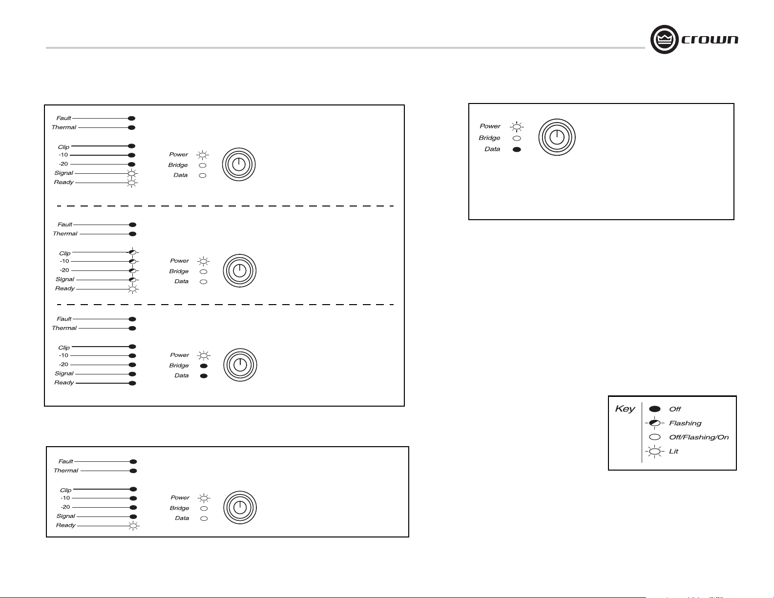
CONDITION: No sound, even though
the amp has power. Power LED is on with-
out flashing and the amp is receiving an input signal. Signal indicator is flashing.
POSSIBLE REASON:
• Speakers not connected.
• Open circuit due to speaker failure.
• There is a short on the amplifier output. First
disconnect your speakers from the affected
channel(s) one by one to determine if one of
the loads is shorted.
• Ready LED is off. Channel has been set to
standby mode via the IQ system.
CONDITION: Data indicator not flashing, even though PIP module is
installed and host computer IQ software is active.
POSSIBLE REASON:
• Cable between computer and PIP module is
broken or not connected.
Note: Data indicator flashes only when the installed
PIP2 module is polled for data, or is polled to see
whether it is online.
Operation Manual
CONDITION: No input signal. Signal
indicator is not flashing even though audio is
applied, and the channel is ready..
POSSIBLE REASON:
• Input signal level is very low.
• Level controls are turned down.
“Off/Flashing/On” above means that
the LED can be off, or flashing, or on.
page 19
Page 20

7 Specifications
Minimum Guaranteed Power
(20 Hz - 20 kHz)
2-ohm Dual (per ch.) 150W 250W 1000W 1500W
4-ohm Dual (per ch.) 300W 600W 1000W 1500W
8-ohm Dual (per ch.) 300W 600W 1000W 1250W
16-ohm Dual (per ch.) 300W 300W 625W 625W
70V Dual (per ch.) 300W 600W 1000W 1500W
100V Dual (per ch.) 300W* 600W* 1000W 1500W
4-ohm Bridge 300W 500W 2000W 3000W
8-ohm Bridge 600W 1200W 2000W 3000W
16-ohm Bridge 600W 1200W 2000W 2500W
100V Bridge 600W* 1200W* 2000W 3000W
140V Bridge 600W 1200W 2000W 3000W
200V Bridge 600W* 1200W* 2000W 3000W
Performance CTs 600 CTs 1200 CTs 2000 CTs 3000
Frequency Response (at 1 watt, 20 Hz - 20 kHz) ± 0.25 dB ± 0.25 dB ± 0.25 dB ± 0.25 dB
Signal to Noise Ratio (ref. rated power, 20 Hz to 20 kHz, A-weighted) < 105 dB < 105 dB < 105 dB < 105 dB
Total Harmonic Distortion (THD) at full rated power, from 20 Hz to 20 kHz < 0.1% < 0.1% < 0.35% < 0.35%
Intermodulation Distortion (IMD) 60 Hz and 7 kHz at 4:1, from –40 dB to
full rated power
Damping Factor:
10 Hz to 100 Hz > 3000 > 3000 > 3000 > 3000
Crosstalk (below rated power)
20 Hz to 1kHz > 80 dB > 80 dB > 80 dB > 80 dB
Common Mode Rejection (CMR) (20 Hz to 1 kHz, typical) 50 dB 50 dB 50 dB 50 dB
DC Output Offset < 2 mV < 2mV < 2 mV < 2 mV
Input Impedance nominally balanced, nominally unbalanced 10 k ohms, 5 k ohms 10 k ohms, 5 k ohms 10 k ohms, 5 k ohms 10 k ohms, 5 k ohms
CTs 2-Channel Power Amplifiers
CTs 600
Power at 0.1% THD
< 0.1% < 0.1% < 0.35% < 0.35%
CTs 1200
Power at 0.1% THD
CTs 2000
Power at 0.35% THD
CTs 3000
Power at 0.35% THD
page 20
* With T-170V or TP-170V.
Operation Manual
Page 21

CTs 2-Channel Power Amplifiers
7 Specifications
Performance CTs 600 CTs 1200 CTs 2000 CTs 3000
Maximum Input Level
Before input compression
Absolute maximum
Load Impedance (Note: Safe with all types of loads)
Stereo
+20 dBu
+ 32 dBu
2, 4, 8, 16 ohms and 70V
+20 dBu
+ 32 dBu
2, 4, 8, 16 ohms and 70V
+20 dBu
+ 32 dBu
2, 4, 8, 16, 70V,
and 100V
+20 dBu
+ 32 dBu
2, 4, 8, 16, 70V,
and 100V
Bridge Mono
Voltage Gain (at maximum level setting)
8/4 Ohm Operation
26 dB
70V Operation
100V Operation
Input Sensitivity
2/4/8 ohms
70V
100 V
26 dB gain
Required AC Mains (+15%, – 25%) 120V/60 Hz, 230V/50 Hz 120V/60 Hz, 230V/50 Hz 120V/60 Hz, 230V/50 Hz 120V/60 Hz, 230V/50 Hz
Power Draw at Idle (120 VAC mains) 24W (Standby Mode) 24W (Standby Mode) 35W (Standby Mode) 35W (Standby Mode)
Overall Group Delay < 120 usec < 120 usec < 120 usec < 120 usec
Cooling Continuously variable speed
Dimensions
Width
Height
Depth
Net Weight
Shipping Weight
4, 8, 16 and 140V
35:1 (31 dB)
20:1 (26 dB)
50:1 (34 dB)
1.4V
1.4V
4 ohm load: 1.74V.
8 ohm load: 2.46V
forced air, front-to-back airflow
19 in. (48.3 cm.)
3.5 in. (8.9 cm.)
14.25 in. (36.2 cm.)
22.8 lb (10.3 kg),
27.7 lb (12.6 kg)
4, 8, 16 and 140V
50:1 (34 dB)
20:1 (26 dB)
50:1 (34 dB)
1.4V
1.4V
4 ohm load: 2.46V.
8 ohm load: 3.47V
Continuously variable speed
forced air, front-to-back airflow
19 in. (48.3 cm.)
3.5 in. (8.9 cm.)
14.25 in. (36.2 cm.)
23.4 lb (10.6 kg),
2 8 . 3 l b ( 1 2 . 8 k g )
4, 8, 16, 140V , 200V
63.9:1 (36 dB)
20:1 (26 dB)
50:1 (34 dB)
50:1 (34 dB)
1.4V
1.4V
2.0V
4 ohm load: 3.17V.
8 ohm load: 4.48V
Continuously variable speed
forced air, front-to-back airflow
19 in. (48.3 cm.)
3.5 in. (8.9 cm.)
14.25 in. (36.2 cm.)
27.0 lb (12.2 kg)
32.0 lb (14.5 kg)
4, 8, 16, 140V, 200V
71.4:1 (37 dB)
20:1 (26 dB)
50:1 (34 dB)
50:1 (34 dB)
1.4V
1.4V
2.0V
4 ohm load: 3.88V.
8 ohm load: 5.01V
Continuously variable speed
forced air, front-to-back airflow
19 in. (48.3 cm.)
3.5 in. (8.9 cm.)
14.25 in. (36.2 cm.)
27.7 lb (12.6 kg)
32.7 lb (14.8 kg)
Operation Manual
page 21
Page 22
7 Specifications
CTs 2-Channel Power Amplifiers
page 22
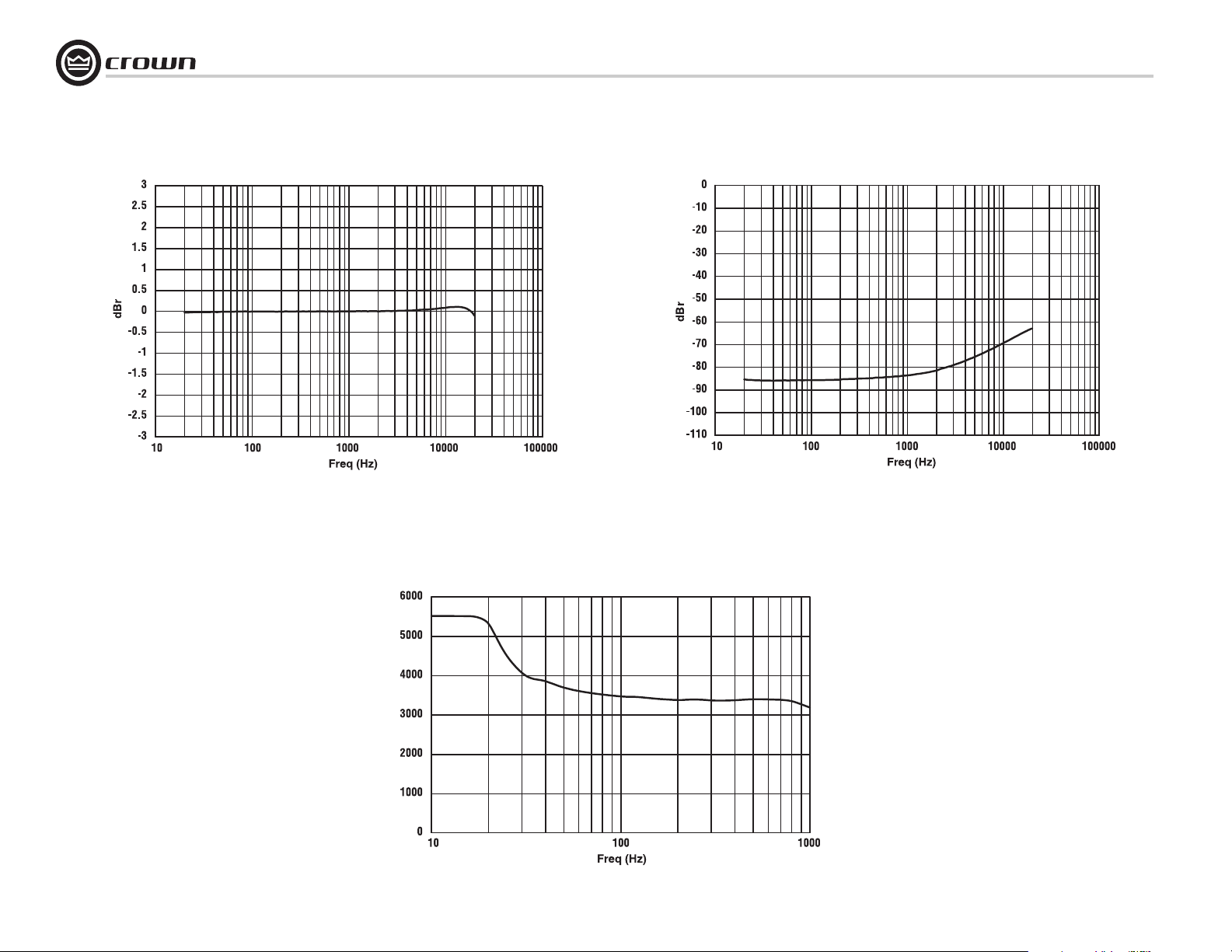
Figure 7.1 CTs 600/1200 Typical Frequency Response (1 W, 8 ohms)
Figure 7.3
CTs 600/1200
Typical Damping Factor
vs. Frequency
Figure 7.2 CTs 600/1200 Typical Crosstalk vs. Frequency
Operation Manual
Page 23
CTs 2-Channel Power Amplifiers
7 Specifications
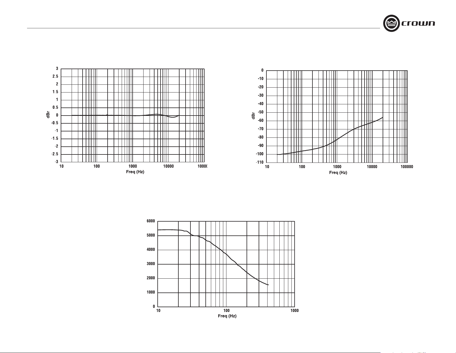
Figure 7.4 CTs 2000/3000 Typical Frequency Response (1W)
Operation Manual
Figure 7.5 CTs 2000/3000 Typical Crosstalk vs. Frequency
Figure 7.6
CTs 2000/3000
Typical Damping Factor
vs. Frequency
page 23
Page 24

8 Service
CTs 2-Channel Power Amplifiers
Crown amplifiers are quality units that rarely require
servicing. Before returning your unit for servicing,
please contact Crown Technical Support to verify
the need for servicing.
This unit has very sophisticated circuitry which
should only be serviced by a fully trained technician. This is one reason why each unit bears the following label:
CAUTION: To prevent electric shock, do not
remove covers. No user serviceable parts
inside. Refer servicing to a qualified technician.
8.1 Worldwide Service
Service may be obtained from an authorized service
center. (Contact your local Crown/Amcron representative or our office for a list of authorized service
centers.) To obtain service, simply present the bill of
sale as proof of purchase along with the defective
unit to an authorized service center. They will handle
the necessary paperwork and repair.
Remember to transport your unit in the original factory pack.
8.2 US and Canada Service
Service may be obtained in one of two ways: from
an authorized service center or from the factory. You
may choose either. It is important that you have your
copy of the bill of sale as your proof of purchase.
8.2.1 Service at a US or Canada Service Center
This method usually saves the most time and effort.
Simply present your bill of sale along with the
defective unit to an authorized service center to
obtain service. They will handle the necessary
paperwork and repair. Remember to transport the
unit in the original factory pack. A list of authorized
service centers in your area can be obtained from
the Crown website at www.crownaudio.com, or by
calling Crown Factory Service.
8.2.2 Factory Service
To obtain factory service, fill out the service
information page found in the back of this manual and send it along with your proof of pur-
chase and the defective unit to the Crown
factory.
For warranty service, we will pay for ground shipping both ways in the United States. Contact Crown
Factory Service to obtain prepaid shipping labels
prior to sending the unit. Or, if you prefer, you may
prepay the cost of shipping, and Crown will reimburse you. Send copies of the shipping receipts to
Crown to receive reimbursement.
Your repaired unit will be returned via UPS ground.
Please contact us if other arrangements are
required.
8.2.3 Factory Service Shipping
Instructions:
1. Before sending a Crown product to the factory
for service, first call the Crown Service Department for a return authorization (RA) number.
2. Be sure to fill out the service information form
that follows and enclose it with your shipment,
either inside the box or in a packing slip envelope securely attached to the outside of the
shipping carton. Do not send the service information form separately. If you are sending the
unit from a Shipping Center, we recommend
taping the form to the product. We also recommend recording the serial number and model
before shipping for your reference.
3. Keep a copy of the serial number and model.
To ensure the safe transportation of your unit to
the factory, ship it in an original factory packing
container. If you don’t have the original carton,
you may obtain a product service foam-inplace shipping pack from Crown Factory Service at the number listed below. For non-warranty service, you may also provide your own
shipping pack, however we still recommend
using a Crown Supplied Shipping Container.
Minimum recommended requirements for
materials are as follows: 275 P.S.I. burst test
Double-Wall carton that allows for 2-inch solid
Styrofoam on all six sides of unit or 3 inches of
plastic bubble wrap on all six sides of unit;
securely seal the package with an adequate car-
ton sealing tape. Do not use light boxes or
“peanuts.” Damage caused by poor packing
cannot be covered under warranty.
4. Do not ship the unit in any kind of cabinet
(wood or metal). Ignoring this warning may
result in extensive damage to the unit and the
cabinet. Accessories are not needed—do not
send the product documentation, cables and
other hardware.
If you have any questions, please contact Crown
Factory Service.
Crown Factory Service
1718 W. Mishawaka Rd.,
Elkhart, Indiana 46517 U.S.A.
Telephone: 574-294-8200
800-342-6939 (North America,
Puerto Rico, and Virgin Islands only)
Facsimile:
574-294-8301 (Technical Support)
574-294-8124 (Factory Service)
Internet:
http://www.crownaudio.com
8.2.4 Crown’s Profit Protection Plan
In the United States, your CTs series amplifier is
also covered by Crown’s advance-replacement
Profit Protection Plan, an enhancement to Crown’s
exceptional Three-Year, No-Fault, Full Warranty.
Crown’s Profit Protection Plan guarantees replacement of your covered amplifier should it fail at any
time during the original three-year warranty period
following the date of original purchase.
Simply contact your local Crown dealer or distributor with model and serial number information to initiate a claim. Your dealer will supply full details on
return procedures for the defective unit as well as
standard and optional delivery times and methods
for the replacement amplifier. Before any claim will
be honored, Crown Factory Service will verify that
there is a problem with the unit.
For more information on the Profit Protection Plan,
please contact Crown Factory Service or your local
Crown representative.
page 24
Operation Manual
Page 25

CTs 2-Channel Power Amplifiers
YEAR
3
9 Warranty
UNITED STATES & CANADA
SUMMARY OF WARRANTY
Crown International, 1718 West Mishawaka
Road, Elkhart, Indiana 46517-4095 U.S.A. warrants to you, the ORIGINAL PURCHASER and
ANY SUBSEQUENT OWNER of each NEW Crown
product, for a period of three (3) years from the
date of purchase by the original purchaser (the
“warranty period”) that the new Crown product is
free of defects in materials and workmanship. We
further warrant the new Crown product regardless of the reason for failure, except as excluded
in this Warranty.
ITEMS EXCLUDED FROM THIS
CROWN WARRANTY
This Crown Warranty is in effect only for failure of
a new Crown product which occurred within the
Warranty Period. It does not cover any product
which has been damaged because of any intentional misuse, accident, negligence, or loss which
is covered under any of your insurance contracts.
This Crown Warranty also does not extend to the
new Crown product if the serial number has been
defaced, altered, or removed.
WHAT THE WARRANTOR WILL DO
We will remedy any defect, regardless of the reason for failure (except as excluded), by repair,
replacement, or refund. We may not elect refund
unless you agree, or unless we are unable to provide replacement, and repair is not practical or
cannot be timely made. If a refund is elected,
then you must make the defective or malfunctioning product available to us free and clear of
all liens or other encumbrances. The refund will
be equal to the actual purchase price, not includ-
ing interest, insurance, closing costs, and other
finance charges less a reasonable depreciation
on the product from the date of original purchase. Warranty work can only be performed at
our authorized service centers or at the factory.
Warranty work for some products can only be
performed at our factory. We will remedy the
defect and ship the product from the service center or our factory within a reasonable time after
receipt of the defective product at our authorized
service center or our factory. All expenses in
remedying the defect, including surface shipping
costs in the United States, will be borne by us.
(You must bear the expense of shipping the
product between any foreign country and the port
of entry in the United States including the return
shipment, and all taxes, duties, and other customs fees for such foreign shipments.)
HOW TO OBTAIN WARRANTY
SERVICE
You must notify us of your need for warranty service within the warranty period. All components
must be shipped in a factory pack, which, if
needed, may be obtained from us free of charge.
Corrective action will be taken within a reasonable time of the date of receipt of the defective
product by us or our authorized service center. If
the repairs made by us or our authorized service
center are not satisfactory, notify us or our authorized service center immediately.
DISCLAIMER OF CONSEQUENTIAL
AND INCIDENTAL DAMAGES
YOU ARE NOT ENTITLED TO RECOVER FROM
US ANY INCIDENTAL DAMAGES RESULTING
FROM ANY DEFECT IN THE NEW CROWN
PRODUCT. THIS INCLUDES ANY DAMAGE TO
ANOTHER PRODUCT OR PRODUCTS RESULTING FROM SUCH A DEFECT. SOME STATES DO
NOT ALLOW THE EXCLUSION OR LIMITATIONS
OF INCIDENTAL OR CONSEQUENTIAL DAMAGES, SO THE ABOVE LIMITATION OR EXCLUSION MAY NOT APPLY TO YOU.
WARRANTY ALTERATIONS
No person has the authority to enlarge, amend,
or modify this Crown Warranty. This Crown
Warranty is not extended by the length of time
which you are deprived of the use of the new
Crown product. Repairs and replacement parts
provided under the terms of this Crown Warranty shall carry only the unexpired portion of
this Crown Warranty.
DESIGN CHANGES
We reserve the right to change the design of any
product from time to time without notice and with
no obligation to make corresponding changes in
products previously manufactured.
LEGAL REMEDIES OF PURCHASER
THIS CROWN WARRANTY GIVES YOU SPECIFIC LEGAL RIGHTS, YOU MAY ALSO HAVE
OTHER RIGHTS WHICH VARY FROM STATE TO
STATE. No action to enforce this Crown Warranty shall be commenced after expiration of the
warranty period.
THIS STATEMENT OF WARRANTY SUPERSEDES
ANY OTHERS CONTAINED IN THIS MANUAL
FOR CROWN PRODUCTS 12/01
Operation Manual
page 25
Page 26

CTs 2-Channel Power Amplifiers
YEAR
3
9 Warranty
SUMMARY OF WARRANTY
Crown International, 1718 West Mishawaka Road,
Elkhart, Indiana 46517-4095 U.S.A. warrants to
you, the ORIGINAL PURCHASER and ANY SUBSEQUENT OWNER of each NEW Crown1 product,
for a period of three (3) years from the date of purchase by the original purchaser (the “warranty
period”) that the new Crown product is free of
defects in materials and workmanship, and we
further warrant the new Crown product regardless
of the reason for failure, except as excluded in this
Warranty.
1 Note: If your unit bears the name “Amcron,” please substitut e
it for the name “Crown” in this warranty.
ITEMS EXCLUDED FROM THIS
CROWN WARANTY
This Crown Warranty is in effect only for failure
of a new Crown product which occurred within
the Warranty Period. It does not cover any product which has been damaged because of any
intentional misuse, accident, negligence, or loss
which is covered under any of your insurance
contracts. This Crown Warranty also does not
extend to the new Crown product if the serial
number has been defaced, altered, or removed.
WORLDWIDE EXCEPT USA & CANADA
WHAT THE WARRANTOR WILL DO
We will remedy any defect, regardless of the reason for failure (except as excluded), by repair,
replacement, or refund. We may not elect refund
unless you agree, or unless we are unable to provide replacement, and repair is not practical or
cannot be timely made. If a refund is elected, then
you must make the defective or malfunctioning
product available to us free and clear of all liens
or other encumbrances. The refund will be equal
to the actual purchase price, not including interest, insurance, closing costs, and other finance
charges less a reasonable depreciation on the
product from the date of original purchase. Warranty work can only be performed at our authorized service centers. We will remedy the defect
and ship the product from the service center
within a reasonable time after receipt of the defective product at our authorized service center.
HOW TO OBTAIN WARRANTY
SERVICE
You must notify your local Crown importer of
your need for warranty service within the warranty
period. All components must be shipped in the
original box. Corrective action will be taken within
a reasonable time of the date of receipt of the
defective product by our authorized service center.
If the repairs made by our authorized service center are not satisfactory, notify our authorized service center immediately.
DISCLAIMER OF CONSEQUENTIAL
AND INCIDENTAL DAMAGES
YOU ARE NOT ENTITLED TO RECOVER FROM US
ANY INCIDENTAL DAMAGES RESULTING FROM
ANY DEFECT IN THE NEW CROWN PRODUCT.
THIS INCLUDES ANY DAMAGE TO ANOTHER
PRODUCT OR PRODUCTS RESULTING FROM
SUCH A DEFECT.
WARRANTY ALTERATIONS
No person has the authority to enlarge, amend, or
modify this Crown Warranty. This Crown Warranty
is not extended by the length of time which you are
deprived of the use of the new Crown product.
Repairs and replacement parts provided under the
terms of this Crown Warranty shall carry only the
unexpired portion of this Crown Warranty.
DESIGN CHANGES
We reserve the right to change the design of any
product from time to time without notice and with
no obligation to make corresponding changes in
products previously manufactured.
LEGAL REMEDIES OF PURCHASER
No action to enforce this Crown Warranty shall be
commenced after expiration of the warranty period.
THIS STATEMENT OF WARRANTY SUPERSEDES
ANY OTHERS CONTAINED IN THIS MANUAL FOR
CROWN PRODUCTS. 7/01
page 26
Operation Manual
Page 27

CTs 2-Channel Power Amplifiers
Crown Factory Service Information
Shipping Address: Crown Factory Service, 1718 W. Mishawaka Rd., Elkhart, IN 46517
Phone: 1-800-342-6939 or 1-574-294-8200 Fax: 1-574-294-8124
Owner’s Name : ________________________________________________________________________________________________________________________________________________________________
Shipping Address: ______________________________________________________________________________________________________________________________________________________________
Phone Number: ________________________________Fax Number: ________________________________ Email ________________________________________________________________________________
Model: __________________________________________________________________________________ Serial Number: ________________________________________________________________________
Purchase Date : ________________________________________________________________________________________________________________________________________________________________
NATURE OF PROBLEM
(Be sure to describe the conditions that existed when the problem occurred and what attempts were made to correct it.)
______________________________________________________________________________________________________________________________________________________________________________
______________________________________________________________________________________________________________________________________________________________________________
______________________________________________________________________________________________________________________________________________________________________________
______________________________________________________________________________________________________________________________________________________________________________
______________________________________________________________________________________________________________________________________________________________________________
______________________________________________________________________________________________________________________________________________________________________________
______________________________________________________________________________________________________________________________________________________________________________
______________________________________________________________________________________________________________________________________________________________________________
Other equipment in system: ___________________________________________________________________________________________________________________________________________________________
______________________________________________________________________________________________________________________________________________________________________________
______________________________________________________________________________________________________________________________________________________________________________
______________________________________________________________________________________________________________________________________________________________________________
If warranty has expired, payment will be: ! Cash/Check ! Visa ! Master Card ! C.O.D. ! Purchase Order for Crown Dealer
Card Number:___________________________________ Exp. Date:___________________
Signature:______________________________________________________________________
ENCLOSE THIS PORTION WITH THE UNIT. DO NOT MAIL SEPARATELY.
Operation Manual
page 27
Page 28

Page 29

Addendum To Operation Manual
Note: This addendum pertains to Section 3 - Setup
Section 5 - Advanced Features and Options
Section 9 - Service
2561953A
REV. A Printed 8/03
Printed in U.S.A.
It is important that you review this addendum
before reviewing the Operation
Manual.
Section 3
With reference to the DUAL/MONO mode switch:
Dual mode allows each amplifier channel to operate independently like a stereo amplifier.
Installation is intuitive - input Channel 1 feeds output Channel 1 and input Channel 2 feeds
output Channel 2. To put the amplifier into the Dual mode, turn it off, slide the DUAL/
MONO switch to DUAL, and properly connect the output wiring.
The MONO switch setting is the BRIDGE-MONO mode and is used to drive loads with a
total impedance of at least 4 ohms. For distributed loudspeaker systems, 140 volts (twice the
normal 70- volt output) is produced. To put the amplifier into the Bridge-Mono mode, turn it
off, and slide the DUAL/MONO switch to MONO. Both outputs will receive the signal from
Channel 1 with the output of Channel 2 inverted so it can be bridged with the Channel 1
output. Please note that there is no provision for paralleling the outputs to obtain a
single high-powered 70-volt constant voltage output.
Section 5
Federal Signal will not offer the T- 170V, TP- 170V, or PIP Modules as indicated in Section
5.3 -Options.
Section 9
For any service related issues, please contact Crown Technical Support. Return the unit to
Crown Factory Service, or to a Crown authorized service center if repairs need to be made.
Page 30

MODELS AR2000-M, AR2000-P AND AR2000-Z
AUDIO ROUTER DEVICES
2561533C
REV. C 12/01
Printed in U.S.A.
INSTALLATION AND SERVICE INSTRUCTIONS
Page 31

INSTALLATION AND SERVICE INSTRUCTIONS
FOR
MODELS AR2000-M, AR2000-P AND AR2000-Z, AUDIO ROUTER DEVICES
SAFETY MESSAGE TO INSTALLERS
People’s safety depends on your safe installation
of our products. It is important to read, understand
and follow all instructions shipped with this product.
Selection of mounting location for this device, its
controls and routing of wiring should be made by the
Facilities Engineer and the Safety Engineer. Listed
below are other important safety instructions and
precautions you should follow.
• This unit must be installed and maintained
by a qualified electrician in accordance with
the National Electrical Code (NFPA 70) or
other national or local codes, under the
direction of the local authority having jurisdiction.
• Do not connect this unit to system wiring
when circuits are energized.
• For optimum sound distribution do not
overload the output lines.
• All audio devices produce loud sounds which,
in certain circumstances, may cause permanent hearing loss. Take appropriate precautions such as wearing hearing protection.
Recommendations in OSHA Sound Level
Standard (29 CFR 1910) should not be exceeded.
• After installation and completion of initial
system test, provide a copy of this instruction
sheet to all personnel responsible for operation, periodic testing and maintenance of this
equipment.
I. GENERAL.
1-1. GENERAL DESCRIPTION.
This device complies with Part 15 of the FCC
Rules. Operation is subject to the following two
conditions: (1) this device may not cause harmful
interference, and (2) this device must accept any
interference received, including interference that
may cause undesired operation.
The Model AR2000-M (see figure 1-1) Audio
Router, is a UL listed and cUL certified central
control device that is capable of routing a selected
audio input to specific zones. It can control signals to
speakers designed for 25Vrms line operation or
70Vrms line operation. It can also control 1Vrms
signals intended to be amplified with a separate
amplification device. The AR2000-M has a public
address (PA) function so voice messages or instructions can be announced over the Audio Router system
through an optional Model MSB-1 or MNC-1 Micro-
phone. The unit can also be used to play background
music generated from an external source over the
Audio Router system.
The Model AR2000-M is an audio multiplexing
device. It is capable of handling two inputs from any
of three different selected source voltages of 1, 25 or
70 volts. The unit has 8 selectable zones which either
the A or the B source is routed to. There is an all call
button that selects all zones. There are also 8 programmable presets on the unit. The presets are
initiated by the front panel buttons or by remote
contacts wired to the back panel. The front panel
also has a monitor speaker jack. A microphone jack
is also available for use with a MSB-1. The microphone has priority over the two user supplied
sources. The telephone feature is protected by an 8
key password. Options available allow changing the
password and recording a message for broadcasting.
Commands entered via the telephone key pad allow
the user to send a message to specified zones. The
microphone and the telephone interface have the
same priority. If the microphone is in use, the telephone interface is disabled. If the phone message
system is in use, the microphone is disabled.
If more than eight zones or eight presets are
needed by the user, a separate AR2000-Z (See Figure
1-2), zone unit, or AR2000-P (See Figure 1-3), preset
unit is available. Each AR2000-Z or AR2000-P unit
will add an additional eight zone or preset controls
respectively. Up to seven additional Preset or Zone
units may be added for a total of 64 zones and 64
presets.
The Model MNC-1 microphone is a hand held,
noise canceling microphone that is ideal for use as a
local microphone. The Model MSB-1 microphone (See
Figure 1-4) is a base station type microphone designed for desktop operation.
The Model AR2000-M may be installed in indoor
installations only as a rack mounted device.
The Model AR2000-M is a rack mount unit that
will fit any standard 19" rack mount cabinet. The
Model AR2000-M can be used for a variety of prioritized signaling purposes, such as playing background
music, paging, start and dismissal, phone messaging
and other communication applications. Additional
advantages of the Model AR2000-M include economical system expansion and long term system flexibility.
The Model AR2000-M routes audio signals and
applies them through zone outputs to the devices in
the system. The AR2000-M connects easily with
-1-
Page 32

PHONE
AUX SPEAKER
MICROPHONE
CH A
CH B
AR2000-M
ALL CALL
ALL CANCEL
FEDERAL
SIGNAL
CORPORATION
R
UNIVERSITY PARK, IL U.S.A.
PRESET 1
ZONE 1
Selectone amplified speakers. A Model AM25CK or
AM70CK Connector Kit is required in each Selectone
device to connect it to the signal line. The Audio
Router device supplies 15W at either 25Vrms or
70Vrms. An additional amplifier must be supplied to
obtain higher wattage levels. Care must be taken to
ensure that the total line impedance of all the connected devices does not cause the line voltage to drop.
Each preset can be manually activated locally
with its associated push button switch on the front
panel or with a contact closure at the associated
preset control input on the back panel. Whenever a
preset is activated, either locally or remotely, its
associated front panel push button LED illuminates
to indicate that the preset has been activated. The
LED remains lit until the preset is deactivated or the
remote contact closure is removed. As an added
feature, when a preset is remotely activated, the
associated LED illuminates and flashes until the
remote contact closure is removed. All AR2000-M
controls are located on the front panel except gain
adjustments which are made on the back panel
during installation.
Operation (normal mode)
Pressing the Channel A or Channel B button
will immediately switch the input to that channel;
the speaker indicator lights will indicate what
speakers are connected. Pushing a speaker button
will turn that speaker on or off; pushing a preset
button will select speakers per that preset, and may
also select Channel A or B (if that preset was configured for a specific channel). Keying the microphone
while in this mode will cause the microphone signal
PRESET 2 PRESET 3
Figure 1-1.
to be sent to the selected speakers; releasing the
microphone will allow Channel A or B operation to
resume.
user to direct audio to specific zones (default is AllCall). The user may select zones using either individual speaker or preset buttons; Channel A or B
operation will not be interrupted until the microphone is actually keyed. Releasing the microphone
will allow Channel A or B to resume operation on its
selected speakers.
in Microphone mode or Channel A/B mode) will cause
all zones to be selected. Pressing any individual zone
when All Call is lit, however, will cancel all the zones
except that one.
function:
select all 64 zones. Otherwise, pressing “All Call” will
cancel all of the zones.
Telephone operation
the router will answer with the Message “ENTER
PASSWORD”. The caller is required to enter their 8
digit password. The caller is given 2 chances to enter
the correct password.
hears the message “GOODBYE” and the system
hangs up the phone line.
PRESET 7PRESET 4
ZONE 4ZONE 2 ZONE 3
ZONE 5 ZONE 6 ZONE 7
PRESET 6PRESET 5
PRESET 8
ALARM
ZONE 8
POWER
290A4120-01
Keying the Microphone button will allow the
Pressing the All Call button (whether the unit is
Pressing All Call will perform the following
If all of the zones are not selected, “All Call” will
When the line attached to the Router is called,
If the correct password is not entered, the caller
AR2000-Z
FEDERAL
SIGNAL
CORPORATION
R
UNIVERSITY PARK, IL U.S.A.
ZONE 2
ZONE 1 ZONE 5ZONE 4ZONE 3 ZONE 7ZONE 6 ZONE 8
Figure 1-2.
-2-
POWER
290A4120-02
Page 33

AR2000-P
4
FEDERAL
SIGNAL
CORPORATION
R
UNIVERSITY PARK, IL U.S.A.
PRESET 2
PRESET 1 PRESET 5PRESET 4PRESET 3 PRESET 7PRESET 6 PRESET 8
Figure 1-3.
POWER
290A4120-03
If the correct password is entered the caller will
hear the message “PRESS 9 KEY TO CHANGE THE
PASSWORD OR 6 KEY TO RECORD A MESSAGE”.
If the caller presses the 9 key, the message
“ENTER NEW PASSWORD” will inform the caller to
enter a new password. The same new password must
be entered twice. Otherwise, the caller will hear the
message “PASSWORD NOT CHANGED” then the
message “GOODBYE” and the system hangs up the
phone line. If the new password is successfully
entered twice, the caller will hear the message
“PASSWORD CHANGED” then the message
“GOODBYE” and the system hangs up the phone
line.
If the caller presses the 6 key, the message
“RECORD MESSAGE, PRESS # KEY TO BROADCAST YOUR MESSAGE” prompts the caller to start
speaking. The message can be up to 90 seconds long.
If the user exceeds 90 second duration, the message
will not play back.
At any time during the call, the caller can enter
the # key or hang-up the phone to exit. Also, when a
key input is necessary, the caller has 5 seconds to
enter a key or the system hangs up automatically.
The password can be returned to the default
“12345678” by opening the cover of the Router and
setting switch SW1 position #4 to the “ON” position
for 5 seconds with the power “ON”.
Default is to all zones. Phone receiving is
disabled during message playback; therefore, subsequent calls must wait for the current message to be
completed before another recording will take place.
Preset operation
The preset optos are a combination of edge and
level-tripped. If the system sees an active edge on an
opto, it will set the input and output relays for the
corresponding preset. The relays will remain set
until the input goes away.
Setting a Preset:
To set a preset, select the zones desired for the
preset by pressing and releasing the appropriate zone
button. The LED corresponding to that zone will
illuminate. Select the input source (Channel A or
Channel B) for that preset. Press and hold the
appropriate preset button until it begins to flash.
The preset is now set.
To recall a preset simply select the preset by
pressing and releasing the associated preset button.
1-2. CHASSIS DESCRIPTION.
The Model AR2000-M is assembled in a black,
sprayed aluminum 3-piece housing approximately
17.5” wide by 14.25" deep by 3.5" high. It is intended
to be rack mounted in a standard 19” rack mount
cabinet.
The housing is held together with eighteen
screws, eight on the front panel, six on the rear panel
and four securing the top to the sides.
The main printed circuit board is attached to the
lower housing with seven screws. Separate wiring
harnesses connect the front and rear boards to the
main printed circuit board. The front panel switches
are designated as CH A, CH B, ALL CALL, CANCEL
ZONE 1 through ZONE 8 and PRESET 1 through
PRESET 8.
The Model AR2000-P is assembled in a black,
sprayed aluminum 3-piece housing approximately
17.5” wide by 10.125" deep by 1.75" high. It is in-
290A4120-0
Figure 1-4.
tended to be rack mounted in a standard 19” rack
mount cabinet. The housing is held together with
-3-
Page 34

twelve screws, four on the front panel, four on the
rear panel and four securing the top to the sides. The
front panel switches are designated as PRESET 1
through PRESET 8.
The Model AR2000-Z is assembled in a black,
sprayed aluminum 3-piece housing approximately
17.5” wide by 10.125" deep by 1.75" high. It is intended to be rack mounted in a standard 19” rack
mount cabinet. The housing is held together with
twelve screws, four on the front panel, four on the
rear panel and four securing the top to the sides. The
front panel switches are designated as ZONE 1
through ZONE 8.
1-3. CONTROL CIRCUITRY.
A. Control Circuitry.
1-4. POWER.
WARNING
In order to prevent power to the AR2000-M
from being accidentally turned off, the unit
has a power switch located on the back of the
unit. Before performing any installation or
maintenance, ensure that power is disconnected.
The front panel has a green LED to indicate the
presence of primary power. It also has a red LED to
indicate the presence of secondary power in use. The
AR2000-M can be operated from either a 120VAC,
240VAC or a 24VDC power source. The AC power is
connected via the power cord, which requires manual
switching in order to operate. 24VDC Backup connects via the rear terminals directly underneath the
4-Amp, Bussman-type GMT indicating fuse.
The control circuitry in the AR2000-M has a
built-in priority level feature. The local microphone
has the highest priority level when activated. If a
preset is initiated by contact closure, the AR2000-M
will grant that preset priority. The Audio Router will
store the current selection first, then activate the
preset. Once the contact closure is removed, the
AR2000-M will return the system to the previous
condition. Pressing cancel will deactivate any currently active selections.
B. All CALL Pushbutton.
The ALL CALL pushbutton switch selects
and connects all zones to the currently selected input
source. Pressing the ALL CALL again returns the
system to the previous condition.
C. CANCEL Pushbutton.
The CANCEL pushbutton when pressed will
reset all the manually activated signaling functions
of the AR2000-M.
D. MONITOR SPKR.
WARNING
If this unit is to be connected to a non-power
limited 24 volt dc supply, the National Electrical Code (NFPA 70) requires that those leads
be separated from other classes of wiring
connected to this unit.
The AR2000-P and the AR2000-Z obtain power
directly from the AR2000-M.
1-5. AUDIO INPUTS.
Channel A and Channel B inputs are provided
in the back of the unit to couple standard 1 volt audio
signal from a background music source such as a
radio receiver, CD player or a tape player. The inputs
can also be selected to accept a 25Vrms or 70Vrms
input source. The Channel A input is selectable from
the front panel by depressing the Channel A selection
button. To select the Channel B input, depress the
Channel B selection button on the front panel. Only
Channel A or Channel B may be activated at one
time. It is not possible to activate both Channel A
and Channel B audio sources simultaneously.
A monitor speaker may be connected to the
unit at this output. Audio to this output will exist
during all conditions except when the microphone is
in use. This prevents any feedback from the microphone.
E. ADDITIONAL ZONES.
An AR2000-Z may be connected to add on
additional 8 zones of control. If desired, up to seven
(7) total AR2000-Z units may be added to provide a
total of 64 zones.
F. ADDITIONAL PRESETS.
An AR2000-P may be connected to add on
additional 8 presets of control. If desired, up to seven
(7) total AR2000-P units may be added to provide a
total of 64 presets.
1-6. MICROPHONE INPUT OPTION.
A Federal Signal Model MSB-1 microphone can
be connected directly to the AR2000-M via the
modular jack provided on the front of the unit (highest priority).
1-7. TELEPHONE INPUT OPTION.
A standard telephone line can be connected
directly to the AR2000-M via the modular phone jack
provided at the back of the unit. This allows the user
to contact the AR2000-M via phone, record a message
and deliver it to zones selected by the phone line
user.
-4-
Page 35

1-8. ELECTRICAL DETAILS.
Termination: Screw terminals for 13 AWG to
23 AWG conductors.
Voltage Range: Selectable 120 VAC
or 240 VAC 50/60 Hz.
Battery backup: 24 VDC
Channel A input: Selectable to be 1 Vrms, 25 Vrms,
or 70 Vrms
Channel B input: Selectable to be 1 Vrms, 25 Vrms,
or 70 Vrms
Onboard Amplifier: 15 Watts maximum
Amplifier
Output Voltage: Selectable to be 1 Vrms, 25 Vrms,
or 70 Vrms
Frequency range: -3dB @ 150 Hz -3dB @ 12 kHz
(no load) -6dB @ 85 Hz -6dB @ 24.8 kHz
Monitor Speaker
output: 300mW typical @ 1 kHz, 8 ohm
Maximum switching
current for each zone: 15 AMPS
-5-
Page 36

II. SPECIFICATIONS.
2-1. AR2000-M POWER INPUT.
Input Voltage 120V,50-60HZ
Standby Current 350 mA
Operating Current 2 A
Power Consumption 240 Watts
Input Voltage 240V, 50-60HZ
Standby Current 160 mA
Operating Current 1 A
Power Consumption 160 Watts
2-2. EMERGENCY POWER SOURCE INPUT.
Input Voltage 24 VDC
Standby Current 650 mA
Operating Current 4 A
2-3. AUDIO INPUT.
A. Local PA (Use optional Model MSB-1 microphone)
Input Impedance 5k Ohms
Input Voltage 16 mVrms (MAX)
B. Channel A / Channel B
Input Impedance 28.87 K ohms @ 1 Vrms position
22.67 K ohms @ 25 Vrms position
22.10 K ohms @ 70 Vrms position
Input Voltage Selectable at 1Vrms, 25Vrms or 70 Vrms
2-4. AUDIO OUTPUTS.
A. Output Impedance
Balanced Sig. line 27 Ohms
B. Output Voltage Levels no Load
Balanced Signal Line @70Volt position 70Vrms
Balanced Signal Line @25Volt position 25Vrms
Balanced Signal Line @1Volt position 1-20Vrms
2-5. REMOTE PRESET ACTIVATION CIRCUIT.
NOTE: It is recommended that the installer use shielded, twisted pair wire in order to minimize any false
activation due to environmental noise.
Type Dry Contact Closure
Line Impedance 1 K ohm (MAX)
Circuit Current 20 mA Max (12VDC)
2-6. REMOTE MIC. ACTIVATION CIRCUIT (PTT).
Type Dry Contact Closure
Line Impedance 100 Ohm (MAX)
Circuit Current 10MA Max (12VDC)
-6-
Page 37

2-7. RELAY CONTACT CLOSURE OUTPUTS.
Relays
Type: Dry Contact Closure
Rating: 15A maximum current per zone
2-8. FUSE.
F1 Type GMC 2A, 250V
F2 Bussman-type GMT 4A
2-9. PHYSICAL.
A. AR2000-M
Weight 16 lb 8 oz. (7.5 kg.)
Dimensions (HWD) 3.5" x 17 3/8" x 14.25"
Case Material 14GA Aluminum
B. AR2000-P
Weight 3 lb, 15 oz. (1.8 kg)
Dimensions (HWD) 1.75" x 17 3/8” x 10.125"
Case Material 14GA Aluminum
89mm x 442mm x 362mm
44.5mm x 442mm x 257mm
C. AR2000-P
Weight 3 lb, 15 oz. (1.8 kg)
Dimensions (HWD) 1.75" x 17 3/8” x 10.125"
Case Material 14GA Aluminum
2-10. AGENCY APPROVALS.
A. UL AND cUL Certifications.
UL 813, (AZJX) Commercial Audio and Radio Equipment, Systems and accessories
C22.2 No. 1-98, (AZJX7) Audio, Video, and Similar Electronic Equipment
B. CSA Certification-Pending
C22.2 No. 1-98, Audio, Video, and Similar Electronic Equipment
C. FCC.
This device complies with Part 15 of the FCC Rules. Operation is subject to the following
two conditions: (1) this device may not cause harmful interference, and (2) this device
must accept any interference received, including interference that may cause undesired operation.
44.5mm x 442mm x 257mm
-7-
Page 38

III. INSTALLATION.
SAFETY MESSAGE TO INSTALLERS
Peoples lives depend on proper installation of
our products. It is important to follow all instructions
shipped with these products. These devices are to be
installed by a qualified electrician in accordance with
the National Electrical Code (NFPA 70), or other
national or local codes, under the direction of the
local authority having jurisdiction.
The selection of the mounting location for the
device, its controls and routing of the wiring is to be
accomplished under the direction of the Facilities
Engineer and the Safety Engineer. In addition, listed
below are some other important safety instructions
and precautions you should follow:
• Read and understand all instructions before
installing or operating this equipment.
• Do not connect this unit to the system when
power is on.
• Speakers connected to this system can pro-
duce loud sounds which may cause, in certain
situations, permanent hearing loss. You
should take appropriate precautions such as
wearing hearing protection.
• After installation, test the Audio Router
sound system to ensure proper operation.
• Show these instructions to your Safety
Engineer and then file them in a safe place
and refer to them when maintaining and/or
reinstalling the unit.
• Establish a procedure to routinely check the
sound system for proper activation and
operation.
• Consult the authority having jurisdiction in
your area regarding the proper use and
installation of this product.
The AR2000-P provides four (4) holes for mount-
ing in a standard rack. It utilizes a space of 1U.
The AR2000-Z provides four (4) holes for mount-
ing in a standard rack. It utilizes a space of 1U.
3-3. ELECTRICAL CONNECTIONS.
DANGER
To avoid electrical shock and damage to the
device, do not attempt to connect wires when
power is on.
Terminal blocks are supplied on the AR2000-M
for field wiring. Strip 1/2" of insulation from the
wiring leads. Attach the appropriate wires to the
corresponding terminals. Tighten the screws to
insure that the wires are firmly held in place. The
terminals will accept conductor sizes 23 AWG to 13
AWG.
3-4. SIGNAL LINES.
A. The signal lines transfer the tone signals
and verbal messages from the AR2000-M to the
selected zones and their devices. In order to reduce
the possibility of cross talk, hum and static noise
pick-up, the signal lines must be twisted pair,
shielded audio cable. Although the majority of systems use AWG 18 shielded twisted pair audio cables,
the size of the audio cable should be adjusted to
correspond to the level of audio being routed in your
application.
CAUTION
If too small a wire gauge is used, unacceptable signal voltage drop in the signal line will
cause reduced sound output from the remote
signal device. Only use a cable having wire
gauge greater than 22AWG.
3-1. UNPACKING.
After unpacking the unit, examine it for damage
that may have occurred in transit. If equipment has
been damaged, do not attempt to install or operate it.
File a claim immediately with the carrier stating the
extent of the damage. Carefully check all envelopes,
shipping labels and tags before removing or destroying them.
3-2. MOUNTING ARRANGEMENTS.
The AR2000-M provides four (4) holes for
mounting in a standard rack. It utilizes a space of 2U.
B. Federal does not recommend that new or
existing telephone lines be used as signal lines in an
Audio Router system for the following reasons:
1. Interference from other services or
systems, or interference from the system to other
services.
2. Cross talk, interference or hum induced
by other telephone lines.
3. Extended downtime because of the second
party involvement required to service the lines.
4. The additional cost of installation, interfacing devices and monthly charges as opposed to a
one-time cost of performing the installation.
-8-
Page 39

3-5. MODEL AR2000-M SIGNAL
CONNECTIONS.
CAUTION
Crosstalk can occur between signal lines and
power lines, causing confusing messages,
which interfere with the capability of this
equipment.
Do not install signal lines in the same conduit
with power lines. Avoid routing signal lines on
cable trays with high voltage power lines.
To connect the signal lines of the system to the
AR2000-M, connect a color-coded shielded twisted
pair of audio cables having conductors no smaller
than 18 AWG to + and - of each zone output being
utilized to the appropriate remote device(s). (See
figure 3-1.) Every remote signaling device in the
system will be connected in parallel to these lines.
When connecting the remote devices in parallel to the
signal lines, observe the correct polarity and install
wire nuts over the connections.
NOTE: If using the supplied amplifier or an external
amplifier, the output audio must be connected using
appropriate wire from AUDIO OUT to AUDIO IN
FROM EXTERNAL AMP. If using the on-board
amplifier, directly connect the AUDIO IN FROM
EXTERNAL AMP to the AUDIO OUT terminals on
the back of the AR2000-M. See section 3-4 for recommended wire sizes.
3-6. CONNECTION TO REMOTE DEVICES.
Physically install the remote device(s); follow the
installation instructions packed with the device.
A. 300GC, 300GCX, 300X, 302GC, 302GCX,
302X, 50GC, and 50GCB.
To connect these models to a 25Vrms or
70Vrms signal line, a Model AM25CK or AM70CK
connector card must be used. See figure 3-1 and
instructions below for the appropriate signal line
voltage.
B. 70 Vrms Signal Line Application.
The AR2000-M has provision for connecting
70 Vrms line operated speakers to its output. Connect
the 70 Vrms line at the terminals of Zone 1 – Zone 8
terminal block(s). Connect the speakers in parallel to
this line using 70 Vrms line tap. This output is
selected by setting the switch on the back of the
AR2000-M to the 70 Vrms position. The output audio
must be connected using 16GA wire from AUDIO
OUT to AUDIO IN FROM EXTERNAL AMP. The
Gain may be adjusted using the AUDIO OUT VOLUME control knob.
C. 25 Vrms Signal Line Application.
The AR2000-M has provision for connecting
25 Vrms line operated speakers to its output. Connect
the 25 Vrms line at the terminals of Zone 1 – Zone 8
terminal block(s). Connect the speakers in parallel to
this line using 25 Vrms line tap. This output is
selected by setting the switch on the back of the
AR2000-M to the 25 Vrms position. The output audio
must be connected using 16GA wire from AUDIO
OUT to AUDIO IN FROM EXTERNAL AMP. The
Gain may be adjusted using the AUDIO OUT VOLUME control knob.
D. Low Level Audio Output.
The AR2000-M also has provision for 1 volt
audio output that can be switched to each zone for
individual external amplification. This low level
output is available at the same terminals as in B and
C above. This output is selected by setting the
switch on the back of the AR2000-M to the 1 Vrms
position. The output audio must also be connected
using 18-20GA wire from AUDIO OUT to AUDIO IN
FROM EXTERNAL AMP. The Gain may be adjusted
using the AUDIO OUT VOLUME control knob. It
can also be connected to an analog fiber optic transmitter so that audio can be transmitted over a fiber
optic link in an electrically noisy environment.
E. External Amplifier Connection for Alternate
Power Audio Output.
The AR2000-M also has provision to connect
an external amplifier, such as the Federal Signal
HP440,to be switched to the corresponding zones.
Set the Audio Router up as listed in D above. Connect the 1 volt AUDIO OUT to the audio input of
another amplifier. The output audio must be connected using appropriate wire gauge for the application to the AUDIO IN FROM EXTERNAL AMP (See
figure 3-2.) The Gain may be adjusted using the
AUDIO OUT VOLUME control knob.
CAUTION
Careful attention should be paid in order to
make sure orientation of the signal is not
reversed.
-9-
Page 40

B
ALARM
B
INDICATOR
CAUTION: TO REDUCE THE RISK OF FIRE,
REPLACE ONLY WITH GMC 2A, 250V FUSE
120 VAC, 50/60 HZ, 2A
240 VAC, 50/60 HZ, 1A
(CLASS 2)24VDC
BACKUP POWER
GND +24V
POWER OUT
TO PRESET
CAUTION: TO REDUCE
THE RISK OF FIRE,
REPLACE ONLY WITH
BUSS 250V, 4A GMT FUSE
(CLASS 2)
-
+
POWER OUT
TO AR2000-Z
GND +24V
SIGNAL LINES
SHIELDED
TWISTED PAIR
(CLASS 2) POWER
OUT TO AR2000-P
NO USER-SERVICEABLE PARTS INSIDE. REFER SERVICING TO
WARNING:
QUALIFIED PERSONNEL. TO REDUCE THE RISK OF FIRE OR ELECTRICAL SHOCK,
DO NOT REMOVE COVER OR EXPOSE THIS APPLIANCE TO RAIN OR MOISTURE.
DRY CONTACT IN (N.O.)
ABOVE
PRESET 1
ZONE 1
- +
PRESET 2
AUDIO OUT
ZONE 2
- +
PRESET 3
ZONE 3
- +
PRESET 4
ZONE 4
- +
DRY CONTACT IN (N.O.)
AUDIO OUT
ZONE 6
- +
PRESET 7
ZONE 7
- +
PRESET 5 PRESET 6
ZONE 5
- +
OPTO
COMMON
PRESET 8
AUDIO IN FROM EXTERNAL AMP
OR FROM AUDIO OUT 15W
ZONE 8
- +
+24V
ALL CALL
- +
- +
AUDIO OUT
TO BELOW
CONTROL IN
FROM PRESET
PHONE LINE
NUMBER
( )
CONTROL OUT
TO ZONE
AUDIO OUT
AUDIO OUT
1Vrms
25Vrms
70Vrms
AUDIO OUT(15W)
SIGNAL LINES
SHIELDED
TWISTED PAIR
PHONE
VOLUME
VOLUME
SELECT
- +
MICROPHONE
VOLUME
VOLUME
CH B INPUT
SELECT
1V
rms
25V
rms
70V
rms
CH B INPUT
- +
MONITOR
SPEAKER
VOLUME
CH B
CH A
VOLUME
CH A INPUT
SELECT
1V
rms
25V
rms
70V
rms
CH A INPUT
- +
300GC 300GC 300GC 300GC
AM25CK
120VAC 120VAC
AM25CK
AM25CK
120VAC
HI (+) WHT
LOW (-) WHT
300GC
AM25CK
3-7. POWER CONNECTIONS.
The two basic methods of supplying power to an
Audio Router device are 120VAC 50/60Hz Local
Power or 240VAC 50/60Hz Local Power and 24VDC
Backup Power. The following paragraphs describe
each method along with the advantages and disadvantages of each.
ALARM
INDICATOR
CAUTION: TO REDUCE THE RISK OF FIRE,
REPLACE ONLY WITH GMC 2A, 250V FUSE
120 VAC, 50/60 HZ, 2A
240 VAC, 50/60 HZ, 1A
(CLASS 2)24VDC
BACKUP POWER
GND +24V
POWER OUT
TO PRESET
CAUTION: TO REDUCE
THE RISK OF FIRE,
REPLACE ONLY WITH
BUSS 250V, 4A GMT FUSE
(CLASS 2)
-
+
POWER OUT
TO AR2000-Z
GND +24V
SIGNAL LINES
SHIELDED
TWISTED PAIR
(CLASS 2) POWER
OUT TO AR2000-P
ABOVE
PRESET 1
ZONE 1
- +
NO USER-SERVICEABLE PARTS INSIDE. REFER SERVICING TO
WARNING:
QUALIFIED PERSONNEL. TO REDUCE THE RISK OF FIRE OR ELECTRICAL SHOCK,
DO NOT REMOVE COVER OR EXPOSE THIS APPLIANCE TO RAIN OR MOISTURE.
DRY CONTACT IN (N.O.)
PRESET 2
AUDIO OUT
ZONE 2
- +
PRESET 3
ZONE 3
- +
PRESET 4
ZONE 4
- +
PRESET 5 PRESET 6
DRY CONTACT IN (N.O.)
AUDIO OUT
ZONE 5
ZONE 6
- +
- +
AM25CK
120VAC
Figure 3-1.
PRESET 8
PRESET 7
ZONE 7
ZONE 8
- +
- +
300GC 300GC 300GC
MODEL AR2000-M WITH MODEL 300GC
CONNECTIONS USING INTERNAL AMPLIFIER
AM25CK
120VAC
120VAC
AM25CK
AM25CK
120VAC120VAC
290A4120-05
A. Local Power (see figure 3-3).
In this system, power is supplied to the
AR2000-M device by connecting it to a 120VAC or
240VAC supply in the immediate vicinity of the
device. An input selector switch is provided and must
be set to the appropriate input voltage prior to
turning the device on.
OPTO
+24V
COMMON
ALL CALL
AUDIO IN FROM EXTERNAL AMP
OR FROM AUDIO OUT 15W
- +
- +
AUDIO OUT
TO BELOW
CONTROL IN
FROM PRESET
PHONE LINE
NUMBER
( )
CONTROL OUT
TO ZONE
1Vrms
25Vrms
70Vrms
AUDIO OUT(15W)
PHONE
VOLUME
AUDIO OUT
VOLUME
AUDIO OUT
SELECT
- +
MICROPHONE
VOLUME
VOLUME
CH B INPUT
SELECT
1V
rms
25V
rms
70V
rms
CH B INPUT
- +
MONITOR
SPEAKER
VOLUME
CH B
CH A
VOLUME
CH A INPUT
SELECT
1V
rms
25V
rms
70V
rms
CH A INPUT
- +
HI (+) WHT
LOW (-) WHT
300GC
AM25CK
300GC 300GC 300GC 300GC
AM25CK
120VAC 120VAC
AM25CK
AM25CK
120VAC
AM25CK
120VAC
120VAC
Figure 3-2.
-10-
300GC 300GC 300GC
AM25CK
120VAC
AM25CK
AM25CK
AMP
HP440
OUTPUT
MODEL AR2000-M WITH MODEL 300GC
CONNECTIONS USING EXTERNAL AMPLIFIER
120VAC120VAC
AMP
INPUT
290A4120-06
Page 41

B
TO 120VAC
ALARM
INDICATOR
CAUTION: TO REDUCE THE RISK OF FIRE,
REPLACE ONLY WITH GMC 2A, 250V FUSE
120 VAC, 50/60 HZ, 2A
240 VAC, 50/60 HZ, 1A
(CLASS 2)24VDC
BACKUP POWER
BACKUP POWER
GND +24V
POWER OUT
TO PRESET
CAUTION: TO REDUCE
THE RISK OF FIRE,
REPLACE ONLY WITH
BUSS 250V, 4A GMT FUSE
(CLASS 2)
-
+
POWER OUT
TO AR2000-Z
GND +24V
+
-
PS600
24VDC
(CLASS 2) POWER
OUT TO AR2000-P
ABOVE
PRESET 1
ZONE 1
- +
NO USER-SERVICEABLE PARTS INSIDE. REFER SERVICING TO
WARNING:
QUALIFIED PERSONNEL. TO REDUCE THE RISK OF FIRE OR ELECTRICAL SHOCK,
DO NOT REMOVE COVER OR EXPOSE THIS APPLIANCE TO RAIN OR MOISTURE.
DRY CONTACT IN (N.O.)
PRESET 2
AUDIO OUT
ZONE 2
- +
PRESET 3
ZONE 3
- +
PRESET 4
ZONE 4
- +
PRESET 5 PRESET 6
DRY CONTACT IN (N.O.)
ZONE 5
- +
CAUTION
Improper installation could render this
system inoperable, interfering with the
indicating nature of this product. The installation must conform to applicable local and/or
National Electrical codes.
If an emergency power source is required, a
backup power system described below should be
employed.
WARNING
If the AR2000-M is to be connected to a nonpower limited 24 volt dc supply, the National
Electrical Code (NFPA70) requires that those
leads be separated from other classes of
wiring connected to this unit.
B. Backup Power (See figure 3-3).
1. General.
In the backup power system all of the
local power lines are connected in parallel to one
centrally located power source of 24VDC.
2. Advantages of the Backup Power System.
a. The entire system may be independent of local line voltage.
AUDIO OUT
ZONE 6
- +
PRESET 7
PRESET 8
ZONE 7
ZONE 8
- +
- +
Figure 3-3.
OPTO
+24V
COMMON
ALL CALL
AUDIO IN FROM EXTERNAL AMP
OR FROM AUDIO OUT 15W
- +
- +
AUDIO OUT
TO BELOW
CONTROL IN
FROM PRESET
PHONE LINE
NUMBER
( )
CONTROL OUT
TO ZONE
1Vrms
25Vrms
70Vrms
AUDIO OUT(15W)
PHONE
VOLUME
AUDIO OUT
VOLUME
AUDIO OUT
SELECT
- +
MICROPHONE
VOLUME
VOLUME
CH B INPUT
SELECT
1V
rms
25V
rms
70V
rms
CH B INPUT
- +
MONITOR
SPEAKER
VOLUME
CH B
CH A
VOLUME
CH A INPUT
SELECT
1V
rms
25V
rms
70V
rms
CH A INPUT
- +
290A4120-07
power the local Audio Router Device. If the PS600 is
used, it is not necessary to switch the power source if
a power failure occurs.
3. Disadvantages of Backup Power System.
a. A separate power source for all
remote devices is required. Heavy power lines are
required from that power source to the remote
devices in the system. The size of the power lines is
dependent upon the number of amplifiers and the
total distance of the power loop in order to minimize
the voltage drop while a signal is being routed.
b. Future expansion is limited by the
current capacity of the power source and the power
lines that were initially installed.
c. Central power installations must
comply with local electrical codes. Most power circuits are Class I circuits. Therefore, conduit will
probably be required. Installation costs are higher
than a local power system.
C. AR2000-M System Power Connections.
DANGER
Installation with the system power on could
cause serious injury or death. Do not perform
any installation or maintenance on this
system when power is on. Ensure that the
power is disconnected before proceeding.
b. The entire system can be switched to
an emergency standby power source in the event of a
power failure.
c. The central power system has the
added advantage that an auxiliary power supply,
such as the Federal Model PS600 can be used to
WARNING
This device is to be installed by a trained
electrician who is thoroughly familiar with
the national electrical code (NFPA 70) and
local codes and will follow the guidelines.
-11-
Page 42

WARNING
3-8. CONNECTIONS TO REMOTE SWITCHES.
If this unit is to be connected to a non-power
limited 24 volt dc supply, the National Electrical Code (NFPA70) requires that those leads
be separated from other classes of wiring
connected to this unit.
CAUTION
Cross talk, interference, or hum can be
induced in signal lines, causing poor audio
output or confusing messages, which interferes with the capability of this equipment.
Do not install power lines in the same conduit
as signal lines.
Operating power is connected to AR2000-M
by merely inserting the plug end of the line cord into
any standard 120 volt, 60 Hz outlet. The AR2000-M is
factory set for 120VAC 50/60Hz operation. If 240 volt
operation is preferred, the input block provides a
switch that must be set to this position in order to
function at 240 VAC operation.
If it is desired to use 24 VDC either as a
primary or auxiliary source of power, connect the “+”
terminal of 24 volt DC power supply to the “+”
terminal at the 24VDC BACKUP POWER terminal
on the AR2000-M and “-” terminal of the 24 VDC
power supply to the “-“ terminal at the 24VDC
BACKUP POWER terminal on the AR2000-M located
in the back of the device. (See figure 3-3.)
D. AR2000-P and AR2000-Z Power Connections.
Operating power is connected to AR2000-P
and AR2000-Z by merely connecting 24 VDC from the
AR2000-M to each unit. A terminal block is provided
at the rear-left side of each unit for power connection.
Observe and maintain proper polarity when wiring
the power to these units. Connect the “+” terminal of
the AR2000-M to the “+” terminal of the AR2000-P at
the “+” terminal located in the back of device. Connect the “-” terminal of the AR2000-M to the “-”
terminal of the AR2000-P at the “-” terminal located
in the back of device. An additional 24VDC power
outlet is provided on each AR2000-P and AR2000-Z
for daisy-chaining the power to each sub-unit. Repeat for each AR2000-P and AR2000-Z.
Setup for the AR2000-P presets is done in the
same way as the AR2000-M presets. (See figure 3-4.)
Setup for the AR2000-Z zones is done in the
same way as the AR2000-M. An audio input is
provided on each unit to be routed to each of the
zones it selects. This audio should be connected by
wiring a connection from the master audio output to
the provided input terminals. (See figure 3-5.) Each
additional AR2000-Z should obtain audio in the same
manner from the unit above. (See figure 3-5.)
The AR2000-M presets can be activated remotely by any normally open low current switch
contacts having a current capacity of at least 50 mA
inductive. Figure 3-6 illustrates the connection of
switch contacts to the AR2000-M. S1, S2, S3 and S4
represents remote switch contacts such as those
found in flow switches, program clocks, heat detectors, and smoke detectors. The remotely activated
presets function as long as the activating contacts
remain closed. A jumper needs to be placed across
OPTO COMMON and the provided +24V terminal
next to it on the back of the AR2000-M in order for
the remotely activated presets to function. A remote
switch may be connected to the ALL CALL position if
desired. These are all Normally Open contacts that
initiate with contact closure and remain active until
the contact is opened again.
3-9. INPUT SOURCE CONNECTIONS.
WARNING
Installation or maintenance on AR2000-M
when power is on can result in serious injury
or death. Do not perform any installation or
maintenance to the system when power is on.
Set selector for CH A to the appropriate input
voltage, 1Vrms, 25Vrms or 70Vrms. Connect the “+”
of the source device to the “+” terminal at the Channel A input. Connect the “-“ of the source device to
the “-“ terminal at the Channel A input. Repeat this
process for the Channel B input. CH A and CH B
volume controls are available just above each input
selector to allow the input gain to be adjusted.
CAUTION
Be certain to set the input selector switch to
the appropriate input voltage to avoid damage to the unit and the device being connected.
3-10. COMMUNICATION CONNECTIONS for
AR2000-P and AR2000-Z.
WARNING
It is important that the communication lines
be properly connected to their respective
communication port. Failure to connect the
cables properly will damage the devices and
possibly render them inoperable.
The label on the back of each device indicates
where the communication cable link should be
connected. See figure 3-6 for appropriate placement.
-12-
Page 43

B
AR2000-P
B
(CLASS 2) POWER OUT
TO AR2000-P
GND +24V
AR2000-M OR AR2000-P
(CLASS 2) POWER IN FROM
24VDC
FROM
AR2000-M
NO USER-SERVICEABLE PARTS INSIDE. REFER SERVICING TO QUALIFIED PERSONNEL. TO REDUCE
WARNING:
THE RISK OF FIRE OR ELECTRICAL SHOCK, DO NOT REMOVE COVER OR EXPOSE THIS APPLIANCE TO RAIN OR MOISTURE.
THIS DEVICE COMPLIES WITH PART 15 OF THE FCC RULES,
OPERATION IS SUBJECT TO THE FOLLOWING TWO CONDITIONS:
(1) THIS DEVICE MAY NOT CAUSE HARMFUL INTERFERENCE, AND
(2) THIS DEVICE MUST ACCEPT ANY INTERFERENCE RECEIVED,
INCLUDING INTERFERENCE THAT MAY CAUSE UNDESIRED OPERATION.
SHIELD
SHIELD
TWISTED
TWISTED
PAIR
PAIR
NORMALLY
NORMALLY
OPEN
OPEN
CONTACTS
CONTACTS
REMOTE
REMOTE
SWITCH
SWITCH
DEVICE
DEVICE
**** *** *
*
EXAMPLE OF REMOTE SWITCHES MAY INCLUDE SENSORS,
DOOR TRIGGER SWITCHES, PANEL SWITCHES, OR OTHER
SHIELD
TWISTED
PAIR
NORMALLY
OPEN
CONTACTS
REMOTE
SWITCH
DEVICE
DRY CONTACT IN (N.O.)
PRESET 5PRESET 4PRESET 1 PRESET 2
SHIELD
SHIELD
TWISTED
TWISTED
PAIR
NORMALLY
NORMALLY
OPEN
CONTACTS
CONTACTS
REMOTE
REMOTE
SWITCH
SWITCH
DEVICE
DEVICE
SHIELD
TWISTED
PAIR
PAIR
NORMALLY
OPEN
OPEN
CONTACTS
REMOTE
SWITCH
DEVICE
PRESET 7 PRESET 8PRESET 6PRESET 3
SHIELD
SHIELD
TWISTED
TWISTED
PAIR
PAIR
NORMALLY
NORMALLY
OPEN
OPEN
CONTACTS
CONTACTS
REMOTE
REMOTE
SWITCH
SWITCH
DEVICE
DEVICE
Figure 3-4.
OPTO COMMON
NOT USED
+24V
CAUTION
CONTROL IN
BEFORE
FROM PRESET
INSTALLATION
DISCONNECT
POWER
WARNING
CONNECT CABLES
TO PROPER
JACK
INSTALL JUMPER WIRE
18 GA, 3" TO 4" LONG
ABOVE
CONTROL OUT
TO PRESET
BELOW
TYPICAL REMOTE PRESET CONFIGURATION
AR2000-P
MODULAR CABLE
FROM AR2000-M
290A4120-08
A. Connecting a Model AR2000-Z.
Using the provided 8 position modular cable,
connect the bottom communication port of the
AR2000-M to the top port of the AR2000-Z. (See
section 3-7 part D for an explanation of the power
connection to this unit.)
B. Connecting a Model AR2000-P.
Using the provided 8-position modular cable,
connect the top communication port of the AR2000-M
to the bottom port of the AR2000-P. (Refer to paragraph 3-7.D. for an explanation of the power connection to this unit.)
3-11. TYPICAL CONNECTION EXAMPLES
A. Connecting a CD Player to the Audio Router.
Disconnect power from the AR2000-M.
NO USER-SERVICEABLE PARTS INSIDE. REFER SERVICING TO QUALIFIED PERSONNEL. TO REDUCE
WARNING:
(CLASS 2) POWER IN FROM
THE RISK OF FIRE OR ELECTRICAL SHOCK, DO NOT REMOVE COVER OR EXPOSE THIS APPLIANCE TO RAIN OR MOISTURE.
AR2000-M OR AR2000-Z
THIS DEVICE COMPLIES WITH PART 15 OF THE FCC RULES,
OPERATION IS SUBJECT TO THE FOLLOWING TWO CONDITIONS:
(1) THIS DEVICE MAY NOT CAUSE HARMFUL INTERFERENCE, AND
(2) THIS DEVICE MUST ACCEPT ANY INTERFERENCE RECEIVED,
AR2000-Z
(CLASS 2) POWER
OUT TO AR2000-Z
GND +24V
INCLUDING INTERFERENCE THAT MAY CAUSE UNDESIRED OPERATION.
ZONE 2
- + - +
ZONE 3
- +
AUDIO OUT
ZONE 4ZONE 1
- +
ZONE 5
- +
ZONE 6
- +
ZONE 7
- + - +
Decide which channel will get the CD player
connected to it. Using CH A as an example, set the
voltage selector for the Ch A input to the 1 Vrms
position. Connect the “+” input of CH A to the “+”
output of the CD player. Connect the “-” input of CH
A to the “-” output of the CD player. (See figure 3-7.)
An input level adjust exists just above the input
selector switch for each input channel. Adjust the
input level as needed.
B. Connecting a 300VSC-1044-1 or 300MB to the
Audio Router.
Disconnect power from the AR2000-M.
Connect the output of either device to the CH B input
in the same manner as detailed for the CD player. Be
sure to set the input voltage selector to the appropriate voltage. (See figure 3-7.)
AUDIO IN
CAUTION
CONTROL IN
BEFORE
FROM ZONE
ZONE 8
AUDIO OUT
INSTALLATION
DISCONNECT
POWER
WARNING
CONNECT CABLES
TO PROPER
JACK
ABOVE
CONTROL OUT
TO ZONE
BELOW
24VDC
FROM
AR2000-M
SHIELD
TWISTED
PAIR
300GC
AM25CK
120VAC
300GC
AM25CK
120VAC
300GC
AM25CK
120VAC
300GC
AM25CK
120VAC
300GC
AM25CK
300GC
AM25CK
120VAC120VAC
Figure 3-5.
-13-
SHIELD
TWISTED
PAIR
300GC
AM25CK
120VAC
SHIELD TWISTED
PAIR FROM
AR2000-M AUDIO
300GC
AM25CK
120VAC
MODULAR CABLE
FROM AR2000-M
TYPICAL ZONE CONFIGURATION
AR2000-Z
290A4120-09
Page 44

AR2000-Z
CONTROL IN
FROM ZONE
ABOVE
CONTROL OUT
TO ZONE
BELOW
CAUTION
BEFORE
INSTALLATION
DISCONNECT
POWER
CONNECT CABLES
TO PROPER
JACK
WARNING
AUDIO OUT
AUDIO IN
ZONE 7
- + - +
ZONE 8
- +
ZONE 6
ZONE 3
- +
AUDIO OUT
ZONE 5
- +
- +
ZONE 4ZONE 1
- + - +
ZONE 2
(CLASS 2) POWER IN FROM
AR2000-M OR AR2000-Z
GND +24V
OUT TO AR2000-Z
(CLASS 2) POWER
WARNING:
NO USER-SERVICEABLE PARTS INSIDE. REFER SERVICING TO QUALIFIED PERSONNEL. TO REDUCE
THE RISK OF FIRE OR ELECTRICAL SHOCK, DO NOT REMOVE COVER OR EXPOSE THIS APPLIANCE TO RAIN OR MOISTURE.
(1) THIS DEVICE MAY NOT CAUSE HARMFUL INTERFERENCE, AND
(2) THIS DEVICE MUST ACCEPT ANY INTERFERENCE RECEIVED,
INCLUDING INTERFERENCE THAT MAY CAUSE UNDESIRED OPERATION.
THIS DEVICE COMPLIES WITH PART 15 OF THE FCC RULES,
OPERATION IS SUBJECT TO THE FOLLOWING TWO CONDITIONS:
CONTROL IN
FROM PRESET
ABOVE
CONTROL OUT
TO PRESET
BELOW
CAUTION
BEFORE
INSTALLATION
DISCONNECT
POWER
CONNECT CABLES
TO PROPER
JACK
WARNING
OPTO COMMON
+24V
NOT USED
PRESET 7 PRESET 8PRESET 6PRESET 3
DRY CONTACT IN (N.O.)
PRESET 5PRESET 4PRESET 1 PRESET 2
GND +24V
AR2000-M OR AR2000-P
(CLASS 2) POWER IN FROM
(CLASS 2) POWER OUT
TO AR2000-P
WARNING:
NO USER-SERVICEABLE PARTS INSIDE. REFER SERVICING TO QUALIFIED PERSONNEL. TO REDUCE
THE RISK OF FIRE OR ELECTRICAL SHOCK, DO NOT REMOVE COVER OR EXPOSE THIS APPLIANCE TO RAIN OR MOISTURE.
(1) THIS DEVICE MAY NOT CAUSE HARMFUL INTERFERENCE, AND
(2) THIS DEVICE MUST ACCEPT ANY INTERFERENCE RECEIVED,
INCLUDING INTERFERENCE THAT MAY CAUSE UNDESIRED OPERATION.
THIS DEVICE COMPLIES WITH PART 15 OF THE FCC RULES,
OPERATION IS SUBJECT TO THE FOLLOWING TWO CONDITIONS:
AR2000-P
CONTROL IN
FROM PRESET
ABOVE
CONTROL OUT
TO PRESET
BELOW
CAUTION
BEFORE
INSTALLATION
DISCONNECT
POWER
CONNECT CABLES
TO PROPER
JACK
WARNING
OPTO COMMON
+24V
NOT USED
PRESET 7 PRESET 8PRESET 6PRESET 3
DRY CONTACT IN (N.O.)
PRESET 5PRESET 4PRESET 1 PRESET 2
GND +24V
AR2000-M OR AR2000-P
(CLASS 2) POWER IN FROM
(CLASS 2) POWER OUT
TO AR2000-P
WARNING:
NO USER-SERVICEABLE PARTS INSIDE. REFER SERVICING TO QUALIFIED PERSONNEL. TO REDUCE
THE RISK OF FIRE OR ELECTRICAL SHOCK, DO NOT REMOVE COVER OR EXPOSE THIS APPLIANCE TO RAIN OR MOISTURE.
(1) THIS DEVICE MAY NOT CAUSE HARMFUL INTERFERENCE, AND
(2) THIS DEVICE MUST ACCEPT ANY INTERFERENCE RECEIVED,
INCLUDING INTERFERENCE THAT MAY CAUSE UNDESIRED OPERATION.
THIS DEVICE COMPLIES WITH PART 15 OF THE FCC RULES,
OPERATION IS SUBJECT TO THE FOLLOWING TWO CONDITIONS:
AUDIO OUT
PRESET 7
DRY CONTACT IN (N.O.)
+
ALARM
INDICATOR
-
- +
ZONE 3
PRESET 3
DRY CONTACT IN (N.O.)
- +
ZONE 1
PRESET 1
GND +24V
POWER OUT
TO PRESET
ABOVE
GND +24V
- +
ZONE 2
AUDIO OUT
PRESET 2
- +
ZONE 4
PRESET 4
- +
ZONE 5
- +
ZONE 6
PRESET 5 PRESET 6
- +
CH B INPUT
CH B INPUT
VOLUME
MICROPHONE
VOLUME
AUDIO IN FROM EXTERNAL AMP
OR FROM AUDIO OUT 15W
- +
ZONE 7
- +
ZONE 8
PRESET 8
AUDIO OUT
TO BELOW
- +
- +
ALL CALL
OPTO
COMMON
+24V
AUDIO OUT
CONTROL OUT
TO ZONE
PHONE LINE
NUMBER
( )
25Vrms
AUDIO OUT(15W)
70Vrms
- +
AUDIO OUT
1Vrms
25V
rms
70V
rms
1V
rms
25V
rms
70V
rms
1V
rms
SELECT
VOLUME
CONTROL IN
FROM PRESET
PHONE
VOLUME
CH B
- +
CH A INPUT
SELECT
CH A INPUT
VOLUME
SELECT
CH A
MONITOR
SPEAKER
VOLUME
(CLASS 2) POWER
OUT TO AR2000-P
(CLASS 2)
POWER OUT
TO AR2000-Z
CAUTION: TO REDUCE
THE RISK OF FIRE,
REPLACE ONLY WITH
BUSS 250V, 4A GMT FUSE
(CLASS 2)24VDC
BACKUP POWER
120 VAC, 50/60 HZ, 2A
240 VAC, 50/60 HZ, 1A
CAUTION: TO REDUCE THE RISK OF FIRE,
REPLACE ONLY WITH GMC 2A, 250V FUSE
WARNING:
NO USER-SERVICEABLE PARTS INSIDE. REFER SERVICING TO
QUALIFIED PERSONNEL. TO REDUCE THE RISK OF FIRE OR ELECTRICAL SHOCK,
DO NOT REMOVE COVER OR EXPOSE THIS APPLIANCE TO RAIN OR MOISTURE.
290A4120-11B
RIGHT
LEFT
SPLIT OR CONNECT TO
ONLY LEFT OR RIGHT CHANNEL
CD PLAYER
17 11314110
GAIN
CENTER
TB-1
TB-2
+
SIGNAL
GROUND
120VAC
300MB
120VAC
24VDC
BATTERY
BACKUP
PS600
+-
SIGNAL LINES SHIELDED
TWISTED PAIR
SIGNAL LINES SHIELDED
TWISTED PAIR
JUMPER WIRE
JUMPER WIRE
JUMPER WIRE
JUMPER WIRE
JUMPER WIRE
SWITCH
1
SWITCH
2
SWITCH
3
SWITCH
4
SWITCH
5
SWITCH
6
SWITCH
7
SWITCH
8
AR2000-P
AR2000-P
SWITCH
1
SWITCH
2
SWITCH
3
SWITCH
4
SWITCH
5
SWITCH
6
SWITCH
7
SWITCH
8
SWITCH
1
SWITCH
2
SWITCH
3
SWITCH
4
SWITCH
5
SWITCH
6
SWITCH
7
SWITCH
8
SWITCH
1
SWITCH
2
SWITCH
3
SWITCH
4
SWITCH
5
SWITCH
6
SWITCH
7
SWITCH
8
SWITCH
1
SWITCH
2
SWITCH
3
SWITCH
4
SWITCH
5
SWITCH
6
SWITCH
7
SWITCH
8
TWISTED
PAIR
BLUE YELLOW
TWISTED
PAIR
BLUE YELLOW
TWISTED
PAIR
BLUE YELLOW
TWISTED
PAIR
BLUE YELLOW
TWISTED
PAIR
BLACK RED
TWISTED
PAIR
BLACK RED
TWISTED
PAIR
BLACK RED
TWISTED
PAIR
BLACK RED
TWISTED
PAIR
BLACK RED
TWISTED
PAIR
BLACK RED
TWISTED
PAIR
BLACK RED
TWISTED
PAIR
BLACK RED
WARNING
IF THE AR2000-M IS TO BE CONNECTED TO A NON-POWER LIMITED 24 VOLT DC SUPPLY, SECTION 725-54,
EXCEPTION 2.b.1 OF THE NATIONAL ELECTRICAL CODE (NFPA 70) INDICATES THAT THOSE LEADS MUST BE SEPARATED
BY A MINIMUM OF 0.25 IN.(6.35mm) FROM ALL OTHER CONDUCTORS CONNECTED TO THIS EQUIPMENT.
Figure 3-6.
-14-
Page 45

ALARM
B
INDICATOR
CAUTION: TO REDUCE THE RISK OF FIRE,
REPLACE ONLY WITH GMC 2A, 250V FUSE
120 VAC, 50/60 HZ, 2A
240 VAC, 50/60 HZ, 1A
(CLASS 2)24VDC
BACKUP POWER
CAUTION: TO REDUCE
THE RISK OF FIRE,
REPLACE ONLY WITH
BUSS 250V, 4A GMT FUSE
-
+
TO AR2000-Z
(CLASS 2) POWER
WARNING:
OUT TO AR2000-P
QUALIFIED PERSONNEL. TO REDUCE THE RISK OF FIRE OR ELECTRICAL SHOCK,
DO NOT REMOVE COVER OR EXPOSE THIS APPLIANCE TO RAIN OR MOISTURE.
DRY CONTACT IN (N.O.)
GND +24V
POWER OUT
TO PRESET
ABOVE
PRESET 1
(CLASS 2)
POWER OUT
ZONE 1
GND +24V
- +
NO USER-SERVICEABLE PARTS INSIDE. REFER SERVICING TO
PRESET 2
AUDIO OUT
ZONE 2
- +
PRESET 3
ZONE 3
- +
GROUND
120VAC
PRESET 4
ZONE 4
- +
TB-2
DRY CONTACT IN (N.O.)
AUDIO OUT
ZONE 6
- +
PRESET 7
ZONE 7
- +
PRESET 5 PRESET 6
ZONE 5
- +
CD PLAYER
300MB
GAIN
CENTER
17 11314110
SIGNAL
+
PRESET 8
ZONE 8
-
OPTO
COMMON
AUDIO IN FROM EXTERNAL AMP
OR FROM AUDIO OUT 15W
- +
- +
TB-1
+24V
ALL CALL
- +
AUDIO OUT
TO BELOW
CONTROL IN
FROM PRESET
PHONE LINE
NUMBER
( )
CONTROL OUT
TO ZONE
AUDIO OUT
1Vrms
25Vrms
70Vrms
AUDIO OUT(15W)
RIGHT
LEFT
SIGNAL LINES SHIELDED
TWISTED PAIR
PHONE
VOLUME
VOLUME
AUDIO OUT
SELECT
- +
SPEAKER
VOLUME
VOLUME
CH B
VOLUME
CH A INPUT
CH B INPUT
SELECT
1V
1V
rms
rms
25V
25V
rms
rms
70V
70V
rms
rms
CH B INPUT
CH A INPUT
- +
- +
SIGNAL LINES SHIELDED
TWISTED PAIR
SPLIT OR CONNECT TO
ONLY LEFT OR RIGHT CHANNEL
MONITOR
MICROPHONE
CH A
VOLUME
SELECT
TYPICAL CONNECTION
CD PLAYER AND MODEL 300MB
120VAC
IV. TESTING/OPERATING.
WARNING
Failure to follow all safety precautions and
instructions may result in property damage,
serious injury, or possible death to you or
others.
WARNING
Under certain conditions these devices are
capable of transferring sound loud enough to
cause hearing damage. Adequate hearing
protection should be worn if standing within
close proximity to the device while testing.
Recommendations in OSHA Sound Level
Standard (29CFR 1910) should not be exceeded.
SAFETY MESSAGE TO OPERATORS
Although your Multiplexing system is operating properly it may not be completely effective. People may not hear or heed your
messages. You must recognize this fact and
ensure that your messages achieve their
intended effect through proper test and
training sequences suitable for your specific
application(s).
290A4120-10
Figure 3-7.
4-1. After completion of installation be sure to test
the system to verify that each unit operates satisfactorily.
4-2. Provide a copy of these instructions for the
Safety Engineer(s), System Operators(s) and Maintenance personal.
4-3. TELEPHONE FUNCTION COMMANDS.
A. Changing the Password.
When the line attached to the Router is
called, the Router will answer with the message
“ENTER PASSWORD”. Enter your 8 digit password.
Then the caller will hear the message
“PRESS 9 KEY TO CHANGE THE PASSWORD OR
6 KEY TO RECORD A MESSAGE”.
Press the 9 key, the message “ENTER NEW
PASSWORD” will inform the caller to enter a new
password. The same new password must be entered
twice. The caller will hear the message “PASSWORD
CHANGED” then the message “GOODBYE” and the
system hangs up the phone line.
The password can be returned to the default
“12345678” by opening the cover of the Router and
-15-
Page 46

setting switch SW1 to position #4 to the “ON” position for 5 seconds with the power “ON”.
message will be sent to Zones 1, 4 and 6 of the Master
unit (Bank 1).
B. Recording a Message for Broadcast.
When the line attached to the Router is
called, the Router will answer with the message
“ENTER PASSWORD”. Enter your 8 digit password.
Then the caller will hear the message
“PRESS 9 KEY TO CHANGE THE PASSWORD OR
6 KEY TO RECORD A MESSAGE”.
Press the 6 key, the message “RECORD
MESSAGE, PRESS # KEY TO BROADCAST YOUR
MESSAGE” prompts the caller to start speaking. Say
your message into the phone. Press [#] and hang up
the phone. Your message will be sent to all zones
connected to the Audio Router Device. The message
can be up to 90 seconds long. If the user exceeds 90
second duration, the message will not play back. This
is the procedure for selecting “All Call”.
C. Abort a Message Without Sending it
Anywhere.
Hang up at any time without pressing [#].
D. Send Your Message to a Specific Selected Zone
or Zones.
After saying the message, press any keys on
the telephone keypad from 1-8. These correspond to
the eight zones which are connected to the master
AR2000-M unit. Pressing [1] will select Zone 1,
pressing [5] will select Zone 5 and pressing [8] will
select Zone 8.
For example: To send a message to only Zone
3 of the AR2000-M, after recording the message key
in [3] and then press the [#] key. The message will be
sent only to Zone 3.
For example: To send a message to Zone 3
and Zone 4 of the AR2000-M, after recording the
message key in [3], key in [4] and then press the [#]
key. The message will be sent to Zone 3 and to Zone
4.
If additional AR2000-Z units are connected,
those Zones may also be individually selected. To
accomplish this first key in [*], then key in the bank
number which is associated with the additional zones
you desire to reference (2 –8) and then key in a Zone
for that bank. A maximum of seven (7) additional
Zone Banks may be added to the AR2000-M device.
The master unit is designated as Bank 1.
For example: Keying in [*], [1], [2] will select
to send your message to zone 2 of Bank 1 (located in
the master unit). The [*] says you are about to select
a Bank number and Zone. To send the message to
Bank 1 Zones 1, 4, and 6, after recording a message
key in [*], [1], [1], [4], [6], [# ] and hang up. The
For example: If there is one AR2000-Z unit
connected to the AR2000-M, then it is on Bank 2. To
send a message to only Zone 4 of the AR2000-Z in
Bank 2, key in the following after recording a message: key in [*], [2], [4], and then press the [#] key
and hang up. The message will be sent only to Zone 4
of Bank 2.
For example: If there are two AR2000-Z units
connected to the AR2000-M, then they are on Bank 2
and on Bank 3. To send a message to Zone 4 of the
AR2000-Z in Bank 2 and Zone 5 of the AR2000-Z in
Bank 3, key in the following after recording a message: key in [*], [2], [4] and key in [*], [3], [5] and then
press the [#] key and hang up. The message will be
sent to Zone 4 of Bank 2 and Zone 5 of Bank 3.
For example: To send a message to Zone 6
from Bank 8 after recording a message, key in [*], [8],
[6] and then press the [#] key and hang up. The
message will be sent to Zone 6 of Bank 8.
For example: To select Zones 1,3,5 from Bank
2 and Zones 1, 2 from Bank 3, key in the following
after recording a message: key in [*], [2 ], [1], [3], [5],
[*], [3], [1], [2], [#] and hang up. The message will be
sent to Zones 1, 3 and 5 of Bank 2 and Zones 1 and 2
of Bank 3.
E. Send Your Message to a Selected Preset.
After recording a message, first key in [0 ],
then the associated Bank number(1-8) and then the
Preset number of that Bank (1-8). The zero indicates
you are about to select a preset Bank and preset
number. Only one preset may be selected for a
message.
If additional AR2000-P units are connected,
those Presets may also be individually selected. To
accomplish this, first key in [0], then key in the Bank
number which is associated with the additional
Preset you desire to reference (2 –8) and then key in
a Preset for that bank. A maximum of seven (7)
additional Preset Banks may be added to the
AR2000-M device. The master unit is designated as
Bank 1.
To select preset 2 from Bank 2 after recording
a message, key in [0], [2], [2] and then press the [#]
key and hang up. The message will be sent to Preset
2 of Bank 2.
To select Preset 3 from Bank 8 after recording a message, key in [0], [8], [3] and then press the
[#] key and hang up. The message will be sent to
Preset 3 of Bank 8.
-16-
Page 47

Telephone operation is essentially independent
of other operations except when the device plays its
recorded message. Whatever modes were active
before phone operation will return when the phone
message is complete. In the event that the unit is
stuck in playback mode and needs to be disconnected,
press and hold the “All call” button for 1 second to
force a disconnect.
V. MAINTENANCE
SAFETY MESSAGE TO MAINTENANCE
PERSONNEL
Failure to follow all the safety precautions and
instructions may result in property damage, serious
injury, or death to you or others.
• Read and understand all instructions before
performing maintenance on this unit.
• Do not perform maintenance on this unit
when the circuit is energized.
• Periodic checks should be made to ensure that
effectiveness of this device has not been
reduced.
VI. SERVICE.
The factory will provide technical assistance
with any problem that cannot be handled locally with
satisfaction. Please call customer service for assistance (708) 534-3400.
Communication and shipments should be
addressed to:
Federal Signal Corporation
Electrical Products Division
Service Department
2645 Federal Signal Drive
University Park, Il
60466-3195
• Any maintenance to this unit MUST be
performed by a trained electrician in accordance with the National Electrical Code
(NFPA 70) or other national or local codes.
• Never alter this unit in any manner. Safety
may be jeopardized if alterations are made to
this device.
• The nameplates, which may contain cautionary or other information of importance to
maintenance personnel, should not be obscured by painting or anything of the like.
WARNING
Unauthorized servicing of this unit may
result in diminished performance and/or
property damage, serious injury, or death to
you or others. If a malfunctioning unit is
encountered, do not attempt any field repair
or retro fit of parts. Refer to paragraph VI.
SERVICE for instructions regarding return/
repair of the unit.
-17-
Page 48

MODELS AMR6-2570 AND AMR6-100
INSTALLATION INSTRUCTIONS FOR MODELS AMR6-2570
AND AMR6-100 ADJUSTABLE POWER LOUDSPEAKERS
MODELOS AMR6-2570 Y AMR6-100
INSTRUCCIONES DE INSTALACIÓN PARA PARLANTES DE
POTENCIA AJUSTABLE MODELOS AMR6-2570 Y AMR6-100
MODÈLES AMR6-2570 ET AMR6-100
INSTRUCTIONS D'INSTALLATION POUR LES MODÈLES
AMR6-2570 ET AMR6-100 DE HAUT-PARLEURS RÉGLABLES
Address all communications and shipments to:
Adressez toutes les communications et expéditions à :
Dirija toda la correspondencia y envíos a:
FEDERAL SIGNAL CORPORATION
Electrical Products Division
Service Department
2645 Federal Signal Drive
University Park, IL 60466-3195
Page 49

Page 50

INSTALLATION INSTRUCTIONS FOR MODELS AMR6-2570 AND AMR6-100
ADJUSTABLE POWER LOUDSPEAKERS
Failure to follow all safety precautions and instructions may result in property damage,
serious injury, or death to you or others.
SAFETY MESSAGE TO INSTALLERS
Peoples lives depend on your safe installation of our products. It is important to follow all
instructions shipped with the products. This device is to be installed by a trained electrician who is
thoroughly familiar with the National Electric Code and will follow the NEC guidelines as well as
local codes.
The selection of the mounting location for the device, its controls and routing of the wiring is to
be accomplished under the direction of the Facilities Engineer and the Safety Engineer. In addition,
listed below are some other important safety instructions and precautions you should follow:
• This unit should be installed by a qualified electrician in accordance with NFPA 72,
and national and local Electrical and Fire Codes, under the direction of the
authority having jurisdiction.
• If the unit is not installed in a supervisory system, it must be tested at regular
intervals. Refer to NFPA 72 and the local Fire Codes for this information.
• Read and understand all instructions before installing or operating this equipment.
• Do not connect this unit to the system when power is on.
• All quality speakers of this size and type are capable of producing loud sounds
which may cause, in certain situations, permanent hearing loss. You should take
appropriate precautions such as wearing hearing protection.
• After installation, test the sound system to ensure proper operation.
• All quality speakers of this size and type are capable of producing loud sounds,
which may cause, in certain situations, permanent hearing loss. The device should
be installed far enough away from potential listeners to limit their exposure while
still maintaining its effectiveness. The OSHA Code of Federal Regulations 1910.95
Noise Standard provides guidelines, which may be used regarding permissible
noise exposure levels.
• Show these instructions to your Safety Engineer and then file them in a safe place
and refer to them when maintaining and/or reinstalling the unit.
• Establish a procedure to routinely check the sound system for proper activation
and operation.
• Consult the authority having jurisdiction in your area regarding the proper use
and installation of this product.
A. GENERAL.
The Model AMR6-2570 loudspeaker is Underwriters Laboratories Listed for “Fire Protective
Signaling Use” (category designations UUMW, UEAY, and UEAY7) and the Model AMR6-100 is
Listed for “General Signaling Use” (category designations UEAY, and UEAY7). Both loudspeaker
models are UL listed for use in return air ceiling plenum spaces.
The 25/70 volt model includes an in-line capacitor to provide the isolation necessary for
supervisory use. The 25/ 70 volt model is designed to reproduce electronically generated warning
tones that command rapid recognition of emergency alerting signals. In addition, both loudspeaker
models can reproduce tones, full range voice communication and background music.
-1-
Page 51

B. POWER ADJUSTMENT.
See figures 1 and 2. Multiple power settings are achieved via selection of transformer tabs. The
unit is set at the factory to the 8-watt position. To adjust the power (volume), remove the receptacle/
wire assembly for power setting and place it on the transformer tab corresponding to the desired
power (see table 1). Ensure that the receptacle is fully seated on the tab.
C. SPECIFICATIONS.
The AMR6-2570 and AMR6-100 are high fidelity 6.5" 2-way speakers, incorporating a 14mm
hard dome, neodymium tweeter.
Frequency response rating 110 Hz - 20,000 Hz
Maximum Supervisory Voltage 100Vdc
UL Audibility Rating See Table 1
Audibility Ratings On Axis
@ 10", 8-watt tap
Model AMR6-2570 81 dBa, 25 volt tap, 85.0 dBa, 70 volt tap
Model AMR6-100 85.0 dBa
Weight 3 pounds
Construction ABS Frame - UL VO, 5VA Flame Class
White Powder Coated Steel Grille
D. INSTALLATION.
To avoid electrical shock, do not attempt to install wires when power is on.
1. Electrical Connections.
FOR SUPERVISED SYSTEMS
An uninsulated section of a single conductor must NOT be looped around a terminal and
used as two separate connections. The wire must be severed to provide electrical
supervision of the connection.
Use 2 x 14-18 AWG wiring for speaker models.
Strip 1/4" of insulation from all wiring leads. Attach the appropriate wires to the correspond-
ing terminals on the back of the speaker as shown in figures 1, 2, and 3. The positive or “+” terminal
is marked with a red screw head. Tighten the screws to ensure that the wires are firmly held in
place.
To select the desired wattage, refer to paragraph B. and see figures 1 and 2. Move the
receptacle-wire assembly to set the desired output level. See table 1.
The 25/70 volt model is factory configured for 70 Vrms operation. For 25 Vrms operation
remove the supplied receptacle/wire assembly and place it on the 25V tab (see figure 1). The 100
volt model is factory configured for 100 volt operation and no user connections are required.
2. Mounting (see figure 4).
Both loudspeaker models are mounted using the R6BB back box and R6TB support bridge.
These loudspeakers can easily be mounted to any surface thickness between 1/4" and 1-1/2" due to
the unique adjustable “L” shaped clamps (see figure 4). Mounting of this product using the Model
R6BB back box and Model R6TB support bridge into a ceiling tile is accomplished as follows:
a. Remove the ceiling tile and cut a hole using the enclosed template or using the Model
R6TB support bridge as a template.
b. Bend up the four horseshoe tabs on the bridge (see figure 4).
c. Replace the tile and push back an adjacent tile.
-2-
Page 52

d. Position the support bridge through the adjacent tile opening and secure it over the tile
just cut.
e. Place the back box onto the support bridge ensuring that the four tabs in the bridge
locate into the corresponding slots on the back box (see figure 4).
f. Using pliers, turn the top section of the four tabs 1/8 turn in either direction to secure the
back box to the support bridge.
g. Install the wiring into the back box ensuring that all applicable codes are met.
h. Replace the adjacent tile, connect the wiring to the speaker (see figures 1 and 2), and
secure the speaker using the adjustable “L’ shaped clamps.
E. TESTING/OPERATING.
Under certain conditions these devices are capable of producing sounds loud enough to
cause hearing damage. Adequate hearing protection should be worn if standing within
close proximity to the device while testing. Recommendations in the OSHA Sound Level
Standard (29 CFR 1910) should not be exceeded.
1. After installation is complete, be sure to test the system to verify that each speaker operates
satisfactorily. If it is found that the volume is too low for its location, a higher wattage tap may be
selected. Carefully remove the speaker and move the receptacle to a higher wattage tap (see figures
1 and 2). Reinstall the speaker and retest.
2. After completion of initial system test, establish a program for periodic testing of this device.
Refer to NFPA 72, local Fire Codes and the authority having jurisdiction for
this information.
3. Provide a copy of these instructions for the Safety Engineer, system operator(s) and
maintenance personnel.
SAFETY MESSAGE TO OPERATORS
(Regarding the 25/70 volt model)
Even if your warning system is operating properly, it may not be completely effective.
People may not see, hear or heed your warning signal. You must recognize this fact and
ensure that your warning signal achieves its intended effect through proper testing/
training sequences within your specific application(s), or other appropriate actions.
F. MAINTENANCE.
If cleaning of the front face of this device is required, a mild soap solution is recommended as the
cleaning agent.
NOTE
Although not advised, if painting/touch-up of the grille model’s vinyl face is necessary, a
vinyl-based paint is required for coverage.
SAFETY MESSAGE TO MAINTENANCE PERSONNEL
Failure to follow all safety precautions and instructions in this document may result in
property damage, serious injury, or death to you or others.
• Read and understand all instructions before performing maintenance on this unit.
• Periodic checks should be made to ensure that effectiveness of this device has not
been reduced because the speaker has become clogged with a foreign substance or
because objects have been placed in front of the speaker.
• Any maintenance to this unit MUST be performed by a trained electrician in
accordance with NEC guidelines and local codes.
• Never alter this unit in any manner.
-3-
Page 53

1. Periodically check this device to verify that there are no foreign substances in, or in front of,
the speaker which will reduce its effectiveness.
2. Testing should be periodically performed. Refer to NFPA 72, local Fire Codes and the
authority having jurisdiction for this information.
3. In the event a volume adjustment or other repair is required, be sure to refer to the Safety
Message To Maintenance Personnel before proceeding.
G. SERVICE.
Unauthorized repair/servicing of the unit may result in degradation of performance and/
or property damage, serious injury, or death to you or others. If a malfunctioning unit is
encountered, do not attempt any field repair/retrofit of parts.
Federal Signal will service your equipment or provide technical assistance with any problems
that cannot be handled locally.
Any units returned to Federal Signal for service, inspection, or repair, must be accompanied by a
Return Material Authorization. This R.M.A. can be obtained from the local Distributor or
Manufacturer’s Representative.
At this time a brief explanation of the service requested or the nature of the malfunction, should
be given.
Address all communications and shipments to:
Federal Signal Corporation
Electrical Products Division
Service Department
2645 Federal Signal Drive
University Park, IL 60466-3195
-4-
Page 54

INSTRUCCIONES DE INSTALACIÓN PARA PARLANTES DE POTENCIA
AJUSTABLE MODELOS AMR6-2570 Y AMR6-100
El incumplimiento de todas las instrucciones y precauciones de seguridad puede dar
como resultado daño a la propiedad, lesiones graves o la muerte para usted u otros.
MENSAJE DE SEGURIDAD PARA LOS INSTALADORES
Las vidas de las personas dependen de que usted instale con seguridad nuestros productos. Es
importante seguir todas las instrucciones que se envían con los productos. Este dispositivo debe
ser instalado por un electricista capacitado que esté totalmente familiarizado con el Código
nacional de electricidad y que cumpla tanto con las normas NEC como con los códigos locales.
La elección del sitio de montaje del dispositivo, sus controles y la ruta del cableado debe
realizarse bajo la dirección del ingeniero de la instalación y del ingeniero de seguridad. Además, a
continuación se detallan otras importantes instrucciones y precauciones sobre la seguridad que
usted debe cumplir:
• Esta unidad debe ser instalada por un electricista calificado de acuerdo con NFPA
72, y con los Códigos locales de electricidad e incendio, bajo la dirección de la
autoridad que tenga jurisdicción.
• Si la unidad no se instala en un sistema de supervisión, debe ser probada a
intervalos regulares. Consulte el NFPA 72 y los Códigos locales sobre incendios
por esta información.
• Lea y entienda todas las instrucciones antes de instalar o de hacer funcionar este
equipo.
• No conecte esta unidad al sistema mientras la corriente está encendida.
• Todos los parlantes de calidad de este tipo y tamaño son capaces de producir
sonidos fuertes que pueden causar, en ciertas situaciones, sordera permanente.
Debe tomar las precauciones adecuadas como por ejemplo usar protección para
los oídos.
• Luego de la instalación, pruebe el sistema de sonido para asegurar un
funcionamiento adecuado.
• Todos los parlantes de calidad de este tipo y tamaño son capaces de producir
sonidos fuertes que pueden causar, en ciertas situaciones, sordera permanente. El
dispositivo debe instalarse lo suficientemente alejado de escuchas potenciales
para limitar su exposición mientras continúa manteniendo su efectividad. El
Código OSHA de regulaciones federales 1910.95 Estándar de ruido proporciona
normas, que pueden usarse con referencia a los niveles permitidos de exposición
al ruido.
• Muestre estas instrucciones a su ingeniero de seguridad y luego guárdelas en un
lugar seguro y remítase a ellas cuando realice el mantenimiento y/o reinstale la
unidad.
• Establezca un procedimiento para revisar rutinariamente la instalación del
sistema de sonido para verificar su activación y funcionamiento adecuado.
• Consulte con la autoridad que tenga jurisdicción en su área con respecto al uso y
la instalación adecuada de este producto.
A. GENERAL.
El altavoz modelo AMR6-2570 está certificado por Underwriters Laboratories para el “Uso en la
señalización de protección contra incendio” (denominación de tipo UUMW, UEAY y UEAY7) y el
modelo AMR6-100 está certificado para “Uso de señalización general” (denominación de tipo UEAY
y UEAY7). Ambos modelos de altavoz están certificados por UL para uso en espacios plenos de
cielorrasos de aire de retorno.
El modelo de 25/70 voltios incluye un condensador en línea para proporcionar el aislamiento
necesario para uso de supervisión. El modelo de 25/70 voltios está diseñado para reproducir
-5-
Page 55

tonos de advertencia generados electrónicamente que comandan un reconocimiento rápido de las
señales de alerta de emergencia. Además, ambos modelos de parlantes pueden reproducir tonos,
comunicación de voz de alcance total y música de fondo.
B. AJUSTE DE POTENCIA.
Ver figuras 1 y 2. A través de la selección de las lengüetas del transformador se pueden
obtener múltiples valores de potencia. En la fábrica la unidad se ajusta en la posición de 8 vatios.
Para ajustar la potencia (volumen), quite el ensamblaje del receptáculo/cable para ajustar la
potencia y colóquelos en la lengüeta correspondiente del transformador a la potencia deseada
(ver tabla 1). Asegúrese de que el receptáculo esté totalmente apoyado en la lengüeta.
C. ESPECIFICACIONES.
El AMR6-2570 y el AMR6-100 son parlantes de alta fidelidad de 2 vías de 6,5”, e incorporan
un altavoz de alta frecuencia de neodimio, de domo rígido de 14 mm.
Clasificación de respuesta de frecuencia 110 Hz - 20,000 Hz
Máximo voltaje de supervisión 100VCC
Capacidad de audibilidad UL Vea la Tabla 1
Clasificaciones de audibilidad en
el eje @ 10", derivación de 8 vatios
Modelo AMR6-2570 81 dBa, derivación de 25 volt, 85.0 dBa, derivación de 70 volt
Modelo AMR6-100 85.0 dBa
Peso 3 libras
Estructura Marco ABS - Clase UL “Flame” (llama) 5VA, VO
Rejilla de acero cubierto de polvo blanco
D. INSTALACIÓN.
Para evitar un choque eléctrico, no intente instalar cables cuando está encendido.
1. Conexiones eléctricas.
PARA SISTEMAS SUPERVISADOS
Una sección no aislada de un único conductor NO debe ser enlazada alrededor de un
terminal y utilizada como dos conexiones separadas. El cable debe ser dividido para
proporcionar supervisión eléctrica de la conexión.
Para los modelos de parlantes utilice un cableado de 2 x 12-18 AWG.
Pele 1/4" de aislamiento de todos los conductores del cableado. Conecte loe alambres
apropiados a los terminales correspondientes en la parte posterior del altavoz tal como se muestra
en las figuras 1, 2 y 3. El terminal positivo o “+” está marcado con una cabeza roja de tornillo.
Apriete los tornillos para asegurar que los alambres estén firmemente colocados en su posición.
Para seleccionar la potencia deseada, consulte el párrafo B y vea las figuras 1 y 2. Mueva el
conjunto receptáculo-alambre para fijar el nivel de salida deseado. Vea la tabla 1.
El modelo de 25/70 voltios viene configurado de fábrica para un funcionamiento de 70
Vrms. Para un funcionamiento de 25 Vrms quite el ensamblaje receptáculo/cable que se
proporciona y colóquelo en la pestaña de 25 voltios (vea la figura 2). El modelo de 100 voltios está
configurado de fábrica para funcionar a 100 voltios y no se necesita realizar ninguna conexión por
parte del usuario.
2. Montaje (ver figura 4).
Ambos modelos de parlantes se arman utilizando una caja trasera R6BB y un puente de
soporte R6TB. Estos parlantes pueden ser armados fácilmente sobre una superficie de cualquier
espesor entre 1/4” y 1-1/2” gracias a las exclusivas grapas ajustables en forma de “L” (ver figura
-6-
Page 56

4). El armado de este producto utilizando la caja trasera modelo R6BB y el puente de apoyo
modelo R6TB en una tablilla del cielorraso se logra de la siguiente forma:
a. Quite la tablilla del cielorraso y corte un orificio utilizando la plantilla que se adjunta o el
puente de apoyo modelo R6TB como plantilla.
b. Doble hacia arriba las cuatro pestañas en herradura del puente (ver figura 4).
c. Vuelva a colocar la tablilla y empuje hacia atrás una tablilla contigua.
d. Coloque el puente de apoyo a través de la abertura de la tablilla contigua y asegúrelo
sobre la tablilla recién cortada.
e. Coloque la caja trasera sobre el puente de apoyo asegurándose de que las cuatro
pestañas del puente queden dentro de las ranuras correspondientes en la caja trasera (ver figura 4).
f. Utilizando pinzas, doble la sección superior de las cuatro pestañas 1/8 de vuelta en
cualquier dirección para asegurar la caja trasera al puente de apoyo.
g. Instale el cableado dentro de la caja trasera asegurándose de que se cumplan todos los
códigos que correspondan.
h. Vuelva a colocar la tablilla adyacente, conecte el cableado al altavoz (vea las figuras 1 y 2) y
asegure que el altavoz esté usando las grapas ajustables en forma de “L”.
E. PRUEBA/FUNCIONAMIENTO
Bajo ciertas condiciones estos dispositivos pueden producir sonidos lo suficientemente
altos para causar daños al oído. Debe usar una protección adecuada para el oído si va a
estar en las cercanías al dispositivo durante la prueba. No deben excederse las
recomendaciones de la norma de nivel de sonido OSHA (29 CFR 1910).
1. Después de que la instalación esté completa, asegúrese de probar el sistema para verificar que
ambos altavoces funcionen satisfactoriamente. Si encuentra que el volumen es demasiado bajo para
su ubicación, puede seleccionar una toma de mayor potencia. Retire cuidadosamente el altavoz y
mueva el receptáculo a una toma de mayor potencia (vea las figuras 1 y 2). Instale nuevamente el
altavoz y pruebe de nuevo.
2. Después de completar la prueba inicial del sistema, establezca un programa para pruebas
periódicas de este dispositivo. Remítase al NFPA 72, a los Códigos locales sobre incendios y a la
autoridad que tenga jurisdicción para obtener esta información.
3. Proporciónele una copia de estas instrucciones al Ingeniero de seguridad, a el/los
operador(es) del sistema y al personal de mantenimiento.
MENSAJE DE SEGURIDAD PARA LOS OPERADORES
(Con respecto al modelo de 25/70 voltios)
Incluso si su sistema de advertencia está funcionando adecuadamente, es posible que no
sea completamente efectivo. Las personas pueden no ver, oír o hacer caso de su señal de
advertencia. Debe reconocer este hecho y asegurarse de que su señal de advertencia
logre los efectos pretendidos a través de secuencias adecuadas de pruebas/capacitación
dentro de su(s) aplicación(es) específicas, o por medio de otras acciones adecuadas.
F. MANTENIMIENTO.
Si se necesita limpiar la cara frontal de este dispositivo, se recomienda usar una solución
jabonosa suave como agente de limpieza.
-7-
Page 57

NOTA
Aunque no se recomienda, si es necesario pintar/retocar la cara de vinilo del modelo de
rejilla, se debe utilizar una pintura vinílica para su cobertura.
MENSAJE DE SEGURIDAD PARA EL PERSONAL DE MANTENIMIENTO
El incumplimiento de todas las instrucciones y precauciones de seguridad en este documento
puede dar como resultado daño a la propiedad, lesiones graves o la muerte para usted u otros.
• Lea y comprenda todas las instrucciones antes de efectuar el mantenimiento en
esta unidad.
• Deben realizarse revisiones periódicas para asegurar que no se haya reducido la
efectividad de este dispositivo debido a que el altavoz se haya obstruido con alguna
sustancia extraña o porque se haya colocado objetos frente al altavoz.
• Todo el mantenimiento que se le realice a esta unidad DEBE ser llevado a cabo
por un electricista capacitado de acuerdo con las normas NEC y los códigos locales.
• Nunca altere esta unidad en forma alguna.
1. Revise periódicamente este dispositivo para verificar que no existen sustancias extrañas
dentro ni frente al parlante que puedan reducir su efectividad.
2. Se deben realizar pruebas periódicamente. Remítase al NFPA 72, a los Códigos locales
sobre incendios y a la autoridad que tenga jurisdicción para obtener esta información.
3. En el caso de que se requiera un ajuste de volumen u otra reparación, asegúrese de
consultar el Mensaje de seguridad para el personal de mantenimiento antes de proceder.
G. SERVICIO.
La reparación/servicio no autorizado de la unidad puede dar como resultado el
deterioro del rendimiento y/o daño a la propiedad, lesiones serias o la muerte para
usted u otros. Si se encuentra un malfuncionamiento en la unidad, no intente ningún
tipo de reparación/adaptación de las piezas en el lugar.
Federal Signal llevará a cabo el servicio de su equipo o le proporcionará asistencia técnica con
cualquier problema que no pueda ser manejado en forma local.
Cualquier unidad devuelta a Federal Signal para realizar un servicio, inspección o reparación
debe estar acompañada por una Autorización de devolución de material (R.M.A.). Esta R.M.A. se
puede obtener a través del Distribuidor local o del Representante del fabricante.
En este momento se deberá brindar una breve explicación del servicio solicitado o de la
naturaleza del malfuncionamiento.
Dirija todas las comunicaciones y envíos a:
Federal Signal Corporation
Electrical Products Division
Service Department
2645 Federal Signal Drive
University Park, IL 60466-3195
-8-
Page 58

INSTRUCTIONS D’INSTALLATION POUR LES MODÈLES AMR6-2570 ET AMR6-100
DE HAUT-PARLEURS ÉLECTRIQUES RÉGLABLES
Le non-respect de toutes les précautions de sécurité et instructions peuvent mener à des dommages
à la propriété, des blessures graves ou la mort pour vous ou pour d’autres.
MESSAGE DE SÉCURITÉ POUR LES INSTALLATEURS
La vie des gens dépend de votre installation sécuritaire de nos produits. Il est important de suivre
toutes les Instructions expédiées avec ces produits. Ce dispositif doit être installé par un électricien
bien formé qui connaît le Code national de l’électricité et qui respecte toutes les directives du NEC
ainsi que les codes locaux.
Le choix de l’emplacement de montage de ce dispositif, ses contrôles et l’acheminement du
câblage doit se faire sous la direction de l’ingénieur de l’installation et l’ingénieur responsable de la
sécurité. En outre, vous trouverez ci-après une liste de certaines instructions et précautions de
sécurité importantes à suivre :
• Cet appareil doit être installé par un électricien qualifié conformément à la norme
NFPA 72, et les codes nationaux et locaux de l’électricité et des incendies, sous la
direction de l’autorité responsable.
• Si l’appareil n’est pas installé dans un système de surveillance, il doit être testé à
intervalles réguliers. Reportez-vous à la norme NFPA 72 et aux codes d’incendie
locaux pour cette information.
• Lisez et comprenez bien toutes les instructions avant d’installer ou de faire
fonctionner cet équipement.
• Ne connectez pas cet appareil au système lorsque ce dernier est sous tension.
• Tous les haut-parleurs de qualité de cette taille et de ce type peuvent produire des
sons forts qui pourraient provoquer, dans certaines situations, une perte auditive
permanente. Prenez les précautions voulues comme par exemple, portez une
protection auditive.
• Après l’installation, testez le système pour vous assurer qu’Il fonctionne
correctement.
• Tous les haut-parleurs de qualité de cette taille et de ce type peuvent produire des
sons forts qui pourraient provoquer, dans certaines situations, une perte auditive
permanente. L’appareil devrait être installé assez loin des auditeurs pour limiter
leur exposition tout en conservant l’efficacité de l’appareil. Le code OSHA des
règlements fédéraux sous la norme de bruit 1910.95 offre des indications qui
pourraient servir concernant les niveaux d’intensité de bruits permissibles.
• Montrez ces instructions à votre ingénieur responsable de la sécurité, puis rangezles dans un endroit sûr et reportez-vous à ces instructions pour l’entretien et/ou la
réinstallation de l’appareil.
• Établissez une procédure de vérification de routine du système de son pour assurer
une bonne activation et opération.
• Consultez l’autorité responsable dans votre région quant à la bonne utilisation et
installation de ce produit.
A. GÉNÉRALITÉS.
Le haut-parleur Modèle AMR6-2570 est listé dans Underwriters Laboratories sous «Utilisation
de Signal de Protection contre l’Incendie» (désignations de catégorie UUMW, UEAY, et UEAY7) et le
Modèle AMR6-100 est listé sous “Utilisation de Signal Générale» (désignations de catégorie UEAY,
et UEAY7). Les deux modèles de haut-parleur sont listés sous UL pour utilisation dans des espaces
plénum de plafond d’air de retour.
-9-
Page 59

Le modèle de 25/70 volts inclut un condensateur en ligne pour fournir l’isolation nécessaire aux
fins de supervision. Le modèle de 25/ 70 volts est conçu pour reproduire les signaux d’avertissement
électronique qui commandent les signaux de reconnaissance rapide d’urgence. En plus, les deux
modèles de haut-parleurs peuvent reproduire des tonalités, la gamme complète de la communication vocale et la musique de fond.
B. AJUSTEMENT DE COURANT.
Voir les figures 1 et 2. Vous pouvez obtenir des réglages multiples de courant par sélection des
leviers de transformateur. L’appareil est réglé en usine en position de 8 watts. Pour ajuster le
courant (volume), retirez le montage prise/fil pour régler le courant et placez-le sur le levier du
transformateur correspondant au courant voulu (voir le tableau 1). Assurez-vous que la prise soit
bien installée sur le levier.
C. SPÉCIFICATIONS.
Les modèles AMR6-2570 et AMR6-100 sont des haut-parleurs haute fidélité de 6,5 po /16,4 cm à
2 voies incorporant un globe dur de 14 mm, haut-parleur d’aigus de néodyme.
Capacité en fréquence de réponse 110 Hz - 20,000 Hz
Tension de Supervision Maximum 100V CC
Valeur nominale d’Audibilité UL Voir le Tableau 1
Capacités d’audibilité sur axe
@ 10 po/25,4 cm, dérivation 8 watts
Modèle AMR6-2570 81 dBa, dérivation 25 volts, 85.0 dBa, dérivation 70 volts
Modèle AMR6-100 85.0 dBa
Poids 3 livres/1,361 kg
Construction Enceinte d’ABS - UL VO, catégorie d’incendie 5VA
D. INSTALLATION.
Pour éviter les chocs électriques, n’essayez pas d’installer les fils lorsque l’appareil est
sous tension.
1. Connexions électriques.
Grille d’acier revêtue de poudre blanche
POUR LES SYSTÈMES SUPERVISÉS
Il NE faut PAS enrouler une section non-isolée d’un monoconducteur autour d’une borne
et cela ne doit pas servir comme deux connexions distinctes. Le fil doit être coupé pour
fournir la supervision électrique de la connexion.
Utilisez 2 fils 12-18 AWG pour les modèles à haut-parleurs.
Enlever 1/4" d’isolation de tous les fils conducteurs. Fixer les câbles appropriés aux bornes
correspondantes à l’arrière du haut-parleur comme représenté dans les Figures 1, 2, et 3. La borne
positive ou «+» est marquée par une tête de vis rouge. Serrer les vis pour s’assurer que les câbles
sont correctement mis en place.
Pour sélectionner la consommation en watt, se référer au paragraphe B, et voir les Figures 1
et 2. Déplacer l’ensemble prise-câble pour régler le niveau de puissance voulu. Voir le Tableau 1.
Le modèle de 25/70 volts est configuré en usine pour une opération à 70 de tension rms. Pour un
fonctionnement à 25 de tension rms, retirez l’assemblage fil/prise fourni et placez-le à l’attache de
25V (voir la figure 2). Le modèle de 100 volts est configuré pour un fonctionnement à 100 volts et
aucun besoin de connexions d’utilisateur.
2. Montage (voir la figure 4).
Les deux modèles de haut-parleurs sont installés en utilisant la boîte de fond R6BB et le
pont d’appui R6TB. Ces haut-parleurs s’installent facilement sur toute surface d’une épaisseur
entre 1/4 po/0,635 cm et 1-1/2 po/4 cm à cause des pinces uniques réglables en forme de “L” (voir la
-10-
Page 60

figure 4). Voici comment monter ce produit en utilisant la boîte de fond de modèle R6BB et le pont
d’appui de modèle R6TB dans un carreau du plafond :
a. Retirez le carreau de plafond et coupez un trou avec le gabarit fourni ou en utilisant le
pont d’appui de modèle R6TB comme gabarit.
b. Repliez vers le haut les quatre attaches en fer à cheval sur le pont (voir la figure 4).
c. Replacez le carreau et repoussez un carreau adjacent.
d. Positionnez le pont d’appui par l’ouverture du carreau adjacent et fixez-le sur le carreau
que vous venez de couper.
e. Placez la boîte arrière sur le pont d’appui en vous assurant que les quatre attaches sur le
pont se trouvent dans les fentes correspondantes sur la boîte arrière (voir la figure 4).
f. Utilisez des pinces, tournez la section supérieure des quatre attaches 1/8 de tour dans
l’une ou l’autre direction pour fixer la boîte arrière au pont d’appui.
g. Installez le câblage dans la boîte arrière en vous assurant de respecter tous les codes
applicables.
h. Remettre en place le carreau adjacent, connecter les câbles au haut-parleur (voir les
Figures 1 et 2), et fixer le haut-parleur au moyen des attaches en forme de «L» réglables.
E. TEST/FONCTIONNEMENT.
Dans certaines conditions, ces appareils peuvent émettre des sons suffisamment puissants pour causer un endommagement de l’ouïe. Une protection de l’ouïe adéquate doit
être portée si l’on se trouve très près de l’appareil pendant les essais. Les Recommandations de la Norme de Niveau de Son OSHA (29 CFR 1910) ne doivent pas être dépassées.
1. Après l’installation, veiller à tester le système pour vérifier que chaque haut-parleur fonc-
tionne de m anière satisfaisante. Si il est constaté que le volume est trop bas pour l’emplacement,
un niveau de watts plus élevé peut être sélectionné. Enlever le haut-parleur avec précautions et
connecter la prise à une fiche de source de watts plus élevée (voir les Figures 1 et 2). Réinstaller le
haut-parleur et retester.
2. Après avoir terminé le test initial du système établissez un programme de test à intervalles
réguliers pour cet appareil. Reportez-vous à la norme NFPA 72, les codes d’incendie locaux et
l’autorité ayant juridiction pour cette information.
3. Fournissez une copie de ces instructions à l’ingénieur responsable de la sécurité, l’opérateur
du système et le personnel responsable de l’entretien.
MESSAGE DE SÉCURITÉ POUR LES OPÉRATEURS
(concernant le modèle de 25/70 volts)
Même si votre système d’alarme fonctionne correctement, Il n’est peut-être pas
entièrement efficace. Les gens peuvent ne pas voir, entendre ou respecter votre signal
d’alarme. Vous devez reconnaître ce fait et faire en sorte que votre signal d’alarme
atteigne le but recherché en testant correctement et en établissant de bonnes séquences
au sein de votre ou vos applications précises ou par toutes autres mesures.
F. ENTRETIEN.
S’il faut nettoyer l’avant de l’appareil, il est recommandé d’utiliser une solution savonneuse
comme agent de nettoyage.
-11-
Page 61

NOTE
Bien que cela ne soit pas recommandé, utilisez une peinture de vinyle s’il faut peindre ou
retoucher la face de vinyle des modèles à grille.
MESSAGE DE SÉCURITÉ POUR LE PERSONNEL DE L’ENTRETIEN
Le non-respect de toutes les précautions de sécurité et instructions dans ce document peuvent
mener à des dommages à la propriété, des blessures graves ou la mort pour vous ou pour d’autres.
• Lisez et comprenez bien toutes les instructions avant d’effectuer tout entretien de
cet appareil.
• Des vérifications périodiques doivent être faites pour s’assurer que les performances de cet appareil n’ont pas été réduites du fait que le haut-parleur a été
bouché par des corps étrangers ou que des objets ont été placés devant le hautparleur.
• Tout entretien de cet appareil DOIT être effectué par un électricien formé
conformément aux directives du NEC et des codes locaux.
• Ne modifiez jamais cet appareil de quelque façon que ce soit.
1. Vérifiez périodiquement cet appareil pour vous assurer qu’il n’y ait aucune matière
étrangère à l’intérieur, devant, le haut-parleur qui pourrait réduire son efficacité.
2. Les tests devraient être effectués périodiquement. Reportez-vous à la norme NFPA 72, aux
codes d’incendie locaux et à l’autorité responsable pour cette information.
3. S’il faut un ajustement de volume ou une autre réparation, assurez-vous de vous reporter au
message de sécurité pour le personnel de l’entretien avant de poursuivre.
G. RÉPARATION.
Toute réparation ou tout entretien non autorisé de l’appareil peut mener à une
dégradation de la performance et/ou des dommages à la propriété, de graves blessures,
ou la mort pour vous ou pour d’autres. Si l’appareil fonctionne mal, n’essayez pas de
réparer ou de modifier les pièces sur le terrain.
Federal Signal réparera votre équipement ou fournira une aide technique pour tout problème
qui ne peut être solutionné localement.
Tous les appareils retournés à Federal Signal pour réparation, inspection ou entretien doivent
être accompagnés d’une autorisation de retour du matériel. Cette autorisation s’obtient du
distributeur local ou du représentant du fabricant.
Il faudrait aussi joindre une brève explication du service demandé ou la nature de la défaillance.
Adressez toutes les communications et les expéditions à :
Federal Signal Corporation
Electrical Products Division
Service Department
2645 Federal Signal Drive
University Park, IL 60466-3195
-12-
Page 62

1
A
C
-
English
A. 25/70 Volt Model
B. Primary
C. Secondary
D. Red
E. Field Wiring Terminals (For Connection
to 14-22 AWG conductors)
Note: An uninsulated section of a single conductor
must NOT be looped around the terminal screw and
used as two separate connections. The wire must be
severed to provide electrical supervision of the field
wiring connections.
B
D
+
E
Español
A. Modelo de 25/70 voltios
B. Primario
C. Secundario
D. Rojo
E. Terminales de cableado de campo (para conexión
a conductores de 14-22 AWG)
Nota: Una sección no aislada de un único conductor
NO debe ser enlazada alrededor del tornillo terminal ni ser usada como dos conexiones diferentes. El
alambre debe dividirse para proporcionar
supervisión eléctrica de las conexiones del cableado
de campo.
290A4792
Français
A. Modèle 25/70 Volts
B. Primaire
C. Secondaire
D. Rouge
E. Bornes de Câblage de Champ (Pour Connexion
aux conducteurs 14-22 AWG)
Remarque : Une section non isolée d’un conducteur
simple ne doit PAS être enroulée autour de la vis de la
borne et utilisée comme deux connexions séparées. Le
câble doit être détaché pour assurer la supervision
électrique des connexions de câblage de champ.
-13-
Page 63

2
A
C
English
A. 100 Volt Model
B. Primary
C. Secondary
D. Red
E. Field Wiring Terminals (For Connection
to 14-22 AWG conductors)
Note: An uninsulated section of a single conductor
must NOT be looped around the terminal screw
and used as two separate connections. The wire
must be severed to provide electrical supervision of
the field wiring connections.
B
D
+ E-
Español
A. Modelo de 100 voltios
B. Primario
C. Secundario
D. Rojo
E. Terminales de cableado de campo (para
conexión a conductores de 14-22 AWG)
Nota: Una sección no aislada de un único conductor NO debe ser enlazada alrededor del tornillo
terminal ni ser usada como dos conexiones
diferentes. El alambre debe dividirse para
proporcionar supervisión eléctrica de las
conexiones del cableado de campo.
290A4793
Français
A. Modèle 100 Volts
B. Primaire
C. Secondaire
D. Rouge
E. Bornes de Câblage de Champ (Pour Connexion
aux conducteurs 14-22 AWG)
Remarque : Une section non isolée d’un conducteur simple ne doit PAS être enroulée autour de la
vis de la borne et utilisée comme deux connexions
séparées. Le câble doit être détaché pour assurer la
supervision électrique des connexions de câblage
de champ.
-14-
Page 64

3
4
-
F
+
English
A. Speaker Ground
B. COM
C. IN/OUT
D. Input (+)
E. EOL Device to be supplied by Listed
Fire Alarm Control Panel Manufacturer.
F. Speaker 25 or 70 VRMS Signal Source
G. First Speaker
H. Last Speaker
Français
A. Mise à la terre du haut-parleur
B. COM
C. IN/OUT
D. Entrée (+)
E. Dispositif EOL à fournir par le fabricant
du panneau de contrôle de l’alarme
d’incendie homologué.
F. Haut-parleur de 25 ou 70 de tension RMS
source du signal
G. Premier haut-parleur
H. Dernier haut-parleur
A
D
C
A
BB C C
G
D
C
Español
A. Tierra del parlante
B. COM
C. ENTRADA/SALIDA
D. Entrada (+)
E. Dispositivo EOL a ser suministrado por
el Fabricante del panel de control de
alarma de incendio listado.
F. Fuente de la señal del parlante de 25 ó
70 VRMS
G. Primer parlante
H. Último parlante
H
E
290A418
Table 1
UL Sound Level @ 10' dBa
Tap 25 Volt 70 Volt
1 Watt 71 73
2 Watt 73 75
4 Watt 74 78
8 Watt 76 81
Tableau 1
Dérivation
Niveau de son UL
25 Volts 70 Volts
@ 10' dBa
1 Watt 71 73
2 Watts 73 75
4 Watts 74 78
8 Watts 76 81
Tabla 1
Nivel de sonido UL
@ 10' dBa
Derivación 25 Voltios 70 Voltios
1 Vatio 71 73
2 Vatios 73 75
4 Vatios 74 78
8 Vatios 76 81
-15-
Page 65

4
B
C
D
A
E
English
A. Horseshoe Tabs
B. R6BB Back Box
C. R6TB Support Bridge
D. Ceiling Tile
E. AMR6 Speaker
Español
A. Pestañas de herradura
B. Caja posterior R6BB
C. Puente de soporte R6TB
D. Tablilla del cielorraso
E. Altavoz AMR6
-16-
290A4185B
Français
A. Fiches en fer à cheval
B. Boîte Arrière R6BB
C. Pont de Support R6TB
D. Carreau de Plafond
E. Haut-parleur AMR6
Page 66

Page 67

2561704C
REV. C Printed 10/03
Printed in U.S.A.
Page 68

MODELS AM15 and AM15XD2
INSTALLATION INSTRUCTIONS FOR MODEL AM15 AND AM15XD2
AUDIOMASTER® SPEAKER
MODELOS AM15 y AM15XD2
INSTRUCCIONES DE INSTALACION PARA LOS PARLANTE
MODELOS AM15 Y AM15XD2 AUDIOMASTER®
MODELES AM15 et AM15XD2
INSTRUCTIONS D’INSTALLATION POUR LE HAUT-PARLEUR
AUDIOMASTER® MODELES AM15 ET AM15XD2
Address all communications and shipments to:
Dirija todas la correspondencia y envíos a:
Adressez toutes les communiations et expéditions à:
FEDERAL SIGNAL CORPORATION
Electrical Products Division
2645 Federal Signal Drive
University Park, IL 60466-3195
Page 69

INSTALLATION INSTRUCTIONS FOR MODEL AM15 AND AM15XD2
AUDIOMASTER® SPEAKER
Failure to follow all safety precautions and instructions may result in property damage,
WARNING
serious injury, or death to you or others.
SAFETY MESSAGE TO INSTALLERS
Peoples lives depend on your safe installation of our products. It is important to follow all
instructions shipped with the products. This device is to be installed by a trained electrician who is
thoroughly familiar with the National Electric Code and will follow the NEC guidelines as well as
local codes.
The selection of the mounting location for the device, its controls and routing of the wiring is to be
accomplished under the direction of the Facilities Engineer and the Safety Engineer. In addition,
listed below are some other important safety instructions and precautions you should follow:
• Read and understand all instructions before installing or operating this equipment.
• This unit must be installed by a qualified electrician in accordance with NFPA 72, and National
and local Electrical and Fire Codes, under the direction of the authority having jurisdiction.
• Do not connect this unit to the system when power is on.
• All effective warning speakers produce loud sounds which may cause , in certain situations,
permanent hearing loss. You should take appropriate precautions such as wearing hearing
protection.
• After installation, test the sound system to ensure proper operation.
• All effective warning speakers produce loud sounds, which may cause, in certain situations,
permanent hearing loss. The device should be installed far enough away from potential listeners
to limit their exposure while still maintaining its effectiveness. The OSHA Code of Federal
Regulations 1910.95 Noise Standard provides guidelines which may be used regarding permissible noise exposure levels.
• Show these instructions to your Safety Engineer and then file them in a safe place and refer to
them when maintaining and/or reinstalling the unit.
• After installation and completion of initial system test, a program of periodic testing of this device
must be established. Refer to NFPA 72G, local Fire Codes and the authority having jurisdiction
for this information.
• Consult the authority having jurisdiction in your area regarding the proper use and installation of
this product.
I. GENERAL.
The AudioMaster Model AM15 and AM15XD2 are indoor/outdoor rated, 15 watt power output (8
ohm) loudspeakers for use with general signaling systems such as Federal Signal’s FS.COMMS™
or SelectFone® systems. They are designed to reproduce full range voice communication. They
are suitable for use in areas with high ambient noise levels. The speaker projector is adjustable
and may be repositioned to obtain desired sound distribution.
The AM15XD2 is suitable for use in Class I, Groups A, B, C, & D, Division 2, and Class II,
Groups F & G, Division 2 classified and Class III hazardous locations.
II. SPECIFICATIONS.
Operating Voltage 11 Vrms max
Power Input (selectable) 15 W max
Weight (approx.) 5 lb. (2.25kg)
Impedance 8-ohm
-1-
Page 70

Size 12-5/8" (320mm) high, 8-1/8" (206mm) wide,
8-1/4" (209mm) deep.
Construction Aluminum enclosure painted with grey enamel.
Amplifier housing sealed with neoprene rubber gasket.
III. INSTALLATION.
A. Unpacking.
After unpacking the speaker, examine it carefully for possible damage that may have occurred
in transit. If equipment has been damaged, immediately file a claim with the carrier stating
extent of damage. Carefully check all shipping labels and tags for special instructions before
removing or destroying them.
B. Mounting Arrangements (See figure 1).
CAUTION
To maintain the hazardous location rating of the Model AM15XD2, do not use the 7/8" knockout
(concealed conduit mounting).
The speaker can be mounted on any relatively flat surface. Conduit connection can be made to
1/2" threaded opening at bottom of housing or, in the case of the AM15, to 7/8" knockout
in rear of housing. After the mounting location and mounting method have been selected,
proceed with the applicable instructions below.
WARNING
Property damage, serious injury, or death could occur if an accumulation of water, snow, dust, etc.
resides in the speaker projector, severely reducing or preventing operation of this device.
Mount the unit so speaker projector is pointed horizontally or slightly downward.
1. Flat Surface Mounting.
a. Remove and retain the two screws that secure cover to housing. Remove the cover.
WARNING
Property damage, serious injury, or death could occur if any objects are in front of speaker,
severely reducing optimum sound distribution. For maximum effectiveness, ensure that the front
of the speaker is clear of obstructions.
b. Select the mounting location and place rear of housing against mounting surface.
c. Using the mounting holes (two (2) inside the Model AM15’s housing or four (4) in the
AM15XD2’s external mounting bracket) as a template, scribe drill position marks on the
mounting surface. See figure 1 for mounting hole locations and dimensions.
CAUTION
Before drilling holes in any surface, ensure that both sides of surface are clear of items
that could be damaged.
d. Secure the unit to the mounting surface with #10 screws appropriate for the type of
mounting surface material.
-2-
Page 71

WARNING
Property damage, serious injury or death could occur if the projector is mishandled during
installation or over time. DO NOT rotate the projector more than 180 degrees or
internal speaker wiring may be damaged.
e. Reposition speaker projector if necessary to obtain desired sound coverage.
Loosen collar nut (see figure 1) and move projector to desired position.
f. Before reinstalling the housing cover, read paragraph III.C. Electrical Connections below
and make the necessary electrical connections.
2. Model AM15 Concealed Conduit Mounting.
a. Remove and retain the two screws that secure cover to housing. Remove the cover.
b. Remove the 7/8" knockout at rear of housing.
c. Install the conduit connection.
NOTE
If installation on an existing electrical box is desired, an optional Model CC adapter
plate is required.
d. Select the mounting location and place rear of housing against mounting surface.
e. Using the two (2) mounting holes as a template, scribe drill position marks on the
mounting surface. See figure 1 for mounting hole locations and dimensions.
CAUTION
Before drilling holes in any surface, ensure that both sides of surface are clear of items
that could be damaged.
f. Secure the unit to the mounting surface with #10 screws appropriate for the type of
mounting surface material.
WARNING
Property damage, serious injury or death could occur if the projector is mishandled during
installation or over time. DO NOT rotate the projector more than 180 degrees or
internal speaker wiring may be damaged.
g. Reposition speaker projector if necessary to obtain desired sound coverage.
Loosen collar nut (see figure 1) and move projector to desired position.
h. Before reinstalling the housing cover, read paragraph III.C. Electrical Connections below
and make the necessary electrical connections.
C. Electrical Connections.
DANGER
To avoid electrical shock, do not connect wires when circuits are energized.
NOTE
Audio wires should be sized properly by your licensed installation electrician for your service
application. This cable requires a twisted shielded pair with an 18AWG mimum and should
produce no more than 15% signal loss over the length of the cable run.
National Electrical Code as well as local codes must be adhered to in installation of these
models. All electrical wiring must be routed through approved conduit and fittings. The use of
metal conduit and fittings is required to provide grounding of the enclosure.
1. See figures 2 and 3. Connect the audio common (-) leads to the speaker’s common terminal
and audio positive (+) leads to (+) (SIG) terminal.
-3-
Page 72

WARNING
Property damage, serious injury or death could occur if the housing is not closed properly.
To reduce the possibility of explosion, the Model AM15XD2’s housing cover must
be kept tight while circuits are energized.
2. Be sure the neoprene rubber cover gasket is properly seated in the housing groove and
reinstall housing cover.
IV. TESTING/OPERATING.
WARNING
Under certain conditions these devices are capable of producing sounds loud enough to cause
hearing damage. Adequate hearing protection should be worn if standing within close proximity
to device while testing. Recommendations in the OSHA Sound Level Standard
(29 CFR 1910) should not be exceeded.
A. After installation is complete, be sure to test the system to verify that each speaker operates
satisfactorily. If it is found that the unit is too loud for its location, adjust speaker volume level
at the source.
WARNING
Property damage, serious injury or death could occur if the housing is not closed properly.
To reduce the possibility of explosion, the Model AM15XD2’s housing cover must
be kept tight while circuits are energized.
B. After completion of initial system test, establish a program for periodic testing of this device.
C. Provide a copy of these instructions for the Safety Engineer, system operator(s) and
maintenance personnel.
SAFETY MESSAGE TO OPERATORS
Even if your warning system is operating properly, it may not be completely effective.
People may not hear or heed your warning signal. You must recognize this fact and ensure that
your warning signal achieves its intended effect through proper test/training sequences within
your specific application(s).
V. MAINTENANCE.
SAFETY MESSAGE TO MAINTENANCE PERSONNEL
Failure to follow all safety precautions and instructions may result in property damage, serious
injury, or death to you or others.
• Read and understand all instructions before performing maintenance on this unit.
• To reduce the risk of electrical shock, or ignition of hazardous atmospheres, do not perform
maintenance or service on this unit when circuits are energized.
• Periodic checks should be made to ensure that effectiveness of this device has not been reduced
because speaker has become clogged with a foreign substance or because objects have been
placed in front of the speaker.
• Any maintenance to this unit MUST be performed by a trained electrician in accordance with
NEC guidelines and local codes.
• Never alter this unit in any manner. Safety in hazardous locations may be jeopardized if additional
openings or alterations are made to Model AM15XD2.
• The nameplates, which contain cautionary or other information of importance to maintenance
personnel, should not be obscured if exterior of device is painted.
-4-
Page 73

A. Periodically check this device to verify that there are no foreign substances in, or in front of,
the speaker which will reduce its effectiveness.
B. Testing should be periodically performed. Refer to NFPA 72G, local Fire Codes and the
authority having jurisdiction for information.
C. In the event a volume adjustment or other repair is required, be sure to refer to the Safety
Message For Maintenance Personnel before proceeding.
VI. SERVICE.
WARNING
Unauthorized repair/servicing of the unit may result in degradation of performance and/or property
damage, serious injury, or death to you or others. If a malfunctioning unit is encountered,
do not attempt any field repair/retrofit of parts.
Federal Signal will service your equipment or provide technical assistance with any problems that
cannot be handled locally.
Any units returned to Federal Signal for service, inspection, or repair, must be accompanied by a
Return Material Authorization. This R.M.A. can be obtained from the local Distributor or
Manufacturer’s Representative.
At this time a brief explanation of the service requested or the nature of the malfunction, should
be given.
Address all communications and shipments to:
FEDERAL SIGNAL CORPORATION
Electrical Products Division
Service Department
2645 Federal Signal Drive
University Park, IL 60466-3195
-5-
Page 74

INSTRUCCIONES DE INSTALACION PARA LOS PARLANTE
MODELOS AM15 Y AM15XD2 AUDIOMASTER®
El no seguir todas las instrucciones y precauciones de seguridad puede acarrear daños a la propiedad,
PRECAUCION
heridas serias e incluso su muerte o la de otros.
MENSAJE DE SEGURIDAD A LOS INSTALADORES
La vida de personas depende de la instalación segura de nuestros productos. Es importante seguir
todas las instrucciones empacadas con los productos. Este dispositivo lo debe instalar un electricista
calificado que esté familiarizado con el Código Nacional Eléctrico y siga las normas así como los
códigos locales.
La selección del sitio de montaje del dispositivo, sus controles y la ruta del alambrado, se hará bajo
la dirección del Ingeniero de las facilidades y del Ingeniero de seguridad. Sin embargo, a
continuación se listan algunas otras instrucciones y precauciones de seguridad que se deben seguir:
• Lea y comprenda todas las instrucciones antes de instalar u operar este equipo.
• Esta unidad debe ser instalada por un electricista calificado de acuerdo con el NFPA 72 y los
códigos eléctricos y de incendio Nacionales y locales, bajo la dirección de la autoridad
competente.
• No conecte esta unidad al sistema si está encendido.
• Todos los parlantes efectivos de prevención producen sonidos fuertes, que pueden causar en
ciertas ocasiones, pérdida permanente del oído y se deben tomar las debidas precauciones tales
como usar protectores auditivos.
• Después de instalado, asegúrese de que el sistema de sonido ofrece una operación apropiada.
• Todos los parlantes efectivos de prevención producen sonidos tan fuertes que pueden causar
pérdida permanente del oído. El aparato debe ser instalado lo bastante lejos de los oyentes
potenciales para limitar su exposición mientras mantenga su efectividad. El código OSHA
1910.95 (EEUU) de regulación Federal del ruido, da las guías que deben usarse para los niveles
de exposición permisible al ruido.
• Enseñe estas instrucciones a su Ingeniero de Seguridad y después archívelas en un lugar seguro y
consúltelas cuando le haga mantenimiento o reinstale la unidad.
• Después de la instalación y prueba inicial del sistema, programe pruebas periódicas de este
aparato. Diríjase al NFPA 72G, los Códigos locales de incendio y la autoridad competente para
obtener esta información.
• Consulte con la autoridad competente en su área, lo correspondiente al correcto uso e instalación
de este producto.
I. GENERAL.
Los modelos AM15 y AM15XD2 de AudioMaster están clasificados para uso externo/interno.
Tienen parlantes de 15 vatios de potencia de salida (8 ohmios) para utilizar con los sistemas de
señalización generales como los sistemas SelectFone© o FS.COMMS™ de Federal Signal. Éstos
están diseñados para reproducir comunicación de voz de alcance completo. Son adecuados para
utilizar en áreas con niveles altos de ruido ambiental. El proyector del parlante se ajusta y se
puede cambiar de posición para obtener la distribución de sonido deseada.
El AM15XD2 es adecuado para utilizar en sitios Clase 1, Grupos A, B, C, y D, División 2, Clase
II, Grupos F y G, División 2 clasificados y Clase III peligrosos.
II. ESPECIFICACIONES.
Voltaje de funcionamiento 11 voltios eficaces máx.
Potencia máxima aplicable 15 vatios máx.
Peso (aproximado) 5 libras (2,25 kg)
-6-
Page 75

Impedancia 8 ohmios
Tamaño 302mm (alto), 206mm (ancho), 209mm (largo)
Construcción Caja en aluminio pintada con esmalte gris.
Caja del amplificador sellada con un empaque
de neopreno.
III. INSTALACION.
A. Desempaque.
Después de desempacar la unidad, examine cuidadosamente si hay daños de transporte.
Si hubo daños, haga de inmediato un reclamo al transportador, estableciendo el monto del
daño. Revise cuidadosamente todos los sellos de embarque y marquillas por instrucciones
especiales antes de removerlos o destruirlos.
B. Arreglos de montaje (Ver figura 1).
PREVENCION
Para mantener la clasificación de seguridad en áreas peligrosas del Modelo AM15XD2,
no use el disco removible de 7/8" (montaje en conduit embebido).
El parlante puede ser montado en una superficie relativamente plana. Las conexiones de
conduit pueden ser de rosca de 1/2" con entrada en la parte baja de la caja. También el Modelo
AM15 puede ser montado por un disco removible al fondo de la caja. Después de que la
localización de montaje y el método de montaje ha sido seleccionado, proceda con las
instrucciones que se listan a continuación.
PRECAUCION
Daños a la propiedad, heridas serias o la muerte podrían ocurrir si se presenta una acumulación de
agua, nieve , polvo, etc en el parlante, lo que reduce severamente o evita la operación del dispositivo.
Manatenga el parlante en posición horizontal o con una ligera inclinación hacia abajo.
1. Montaje en Superficie Plana.
a. Afloje los 2 tornillos que aseguran la tapa de la caja. Retire la tapa.
PRECAUCION
Daños a la propiedad, heridos graves o incluso su muerte o la de otros puede ocurrir si cualquier
objeto está en frente del parlante, reduciendo severamente la distribución óptima del sonido.
Para mayor efectividad, asegúrese de que el frente del parlante esté
despejado de cualquier obstáculo.
b. Seleccione la localización de montaje y coloque la parte posterior de la caja contra la
superficie de montaje.
c. Usando los huecos de montaje (dos dentro de la caja del Modelo AM15 o 4 en el soporte
de montaje del Modelo AM15XD2) como una plantilla, marque los puntos a perforar en
la superficie de montaje. Vea la figura 1 para localización y dimensión de los huecos de
montaje.
PREVENCION
Antes de perforar los huecos en cualquier superficie, asegúrese de que ambos lados de la superficie
están despejados de cualquier cosa que puede dañarse.
-7-
Page 76

d. Asegure la unidad a la superficie de montaje con tornillos #10 apropiados para el tipo de
material de la superficie de montaje.
PRECAUCION
Daños a la propiedad, heridas serias e incluso la muerte pueden ocurrir si el parlante es mal
manejado durante la instalación o con el tiempo. NO rote el parlante más de
180º o el cableado interno del parlante sufrirá daños.
e. Reposicione el parlante, si es necesario, para obtener la cobertura de sonido deseada.
Afloje la tuerca (ver figura 1) y mueva el proyector a la posición deseada.
f. Antes de reinstalar la tapa a la caja, lea el párrafo III. C las Conexiones Eléctricas que se
listan abajo y haga todas las conecciones eléctricas necesarias.
2. Montaje en Conduit Embebido del Modelo AM15.
a. Retire y conserve los dos tornilos que aseguran la tapa a la caja. Retire la tapa.
b. Retire el disco variable de 7/8" de la parte posterior de la caja.
c. Instale la conexión del conduit.
NOTA
Si se desea una instalación en una caja eléctrica ya existente, se requiere una
plato adaptador opcional Modelo CC.
d. Seleccione la localización de montaje y coloque la parte posterior de la caja contra la
superficie de montaje.
e. Use los dos huecos de montaje como una platina, marque los puntos a perforar en la
superficie de montaje. Vea la figura 1 para las dimensiones y localización de los huecos
de montaje.
PRECAUCION
Antes de perforar los huecos en cualquier superficie, asegúrese de que ambos lados
de la superficie están libres de cosas que se puedan dañar.
f. Asegure la unidad a la superficie de montaje con tornillos #10 apropiados para el tipo de
material de la superficie de montaje.
PREVENCION
Daños a la propiedad, heridas serias e incluso su muerte o la de otros pueden ocurrir si el proyector
no se maneja adecuadamente durante la instalación o cualquier tiempo después. NO rote el
proyector más de 180º o el cableado interno del parlante puede sufrir daños.
g. Reposicione el proyector si es necesario para obtener la cobertura de sonido deseada.
Afloje la tuerca (ver figura 1) y mueva el proyector a la posición deseada.
h. Antes de reinstalar la tapa de la caja, lea el parágrafo III.C, las conexiones eléctricas que
se listan abajo y haga todas las conecciones eléctricas necesarias.
C. Conexiones Eléctricas.
PELIGRO
Para evitar descargas eléctricas, no conecte cables cuando los circuitos estén energizados.
NOTA
Los cables de audio deben tener el tamaño correcto seleccionado por un electricista instalador
autorizado para su aplicación de servicio. Este cable requiere un par trenzado blindado con un cable
calibre 18AWG como mínimo y debe producir menos de 15% de pérdida de señal
a lo largo del tramo del cable.
Durante la instalación de estos modelos, deben seguirse los Códigos Eléctricos Nacionales así
como los locales. Todo el cableado debe hacerse a través de conduit y accesorios aprobados.
Estos sería de metal si van a servir como tierra de la caja.
-8-
Page 77

1. Vea las figuras 2 y 3. Conecte los conductores comunes (-) de audio al terminal común del
altavoz y los conductores positivos (+) de audio al terminal (+) (SIG).
PREVENCION
Daños a la propiedad, heridas serias e incluso su muerte o la de otros puede ocurrir, si la caja no se
cierra adecuadamente. Para reducir la posibilidad de explosión, la tapa de la caja del Modelo
AM15XD2 se debe mantener bien cerrado mientras los circuitos estén energizados.
2. Asegúrese de que el empaque de neopreno de la caja está bien colocado en la ranura de la
caja y reinstale la tapa de la caja.
IV. PRUEBA/OPERACION.
PRECAUCION
Bajo ciertas condiciones estos dispositivos son capaces de producir sonidos suficientemente fuertes
como para causar daños auditivos. Se debe usar adecuada protección auditiva si se va a premanecer
dentro de cierta proximidad al dispositivo cuando se está probando. Las recomendaciones de la
OSHA (EEUU) con respeto a los Niveles Estándares de Ruido (29CFR 1910) no se deben exceder.
A. Al terminar la instalación asegúrese de probar el sistema para verificar que cada altavoz fun
cione en forma satisfactoria. Si se determina que la unidad tiene un volumen demasiado
alto para el lugar donde está ubicada, ajuste el nivel de volumen del altavoz en la fuente.
PRECAUCION
Daños a la propiedad, heridas serias o incluso su muerte o la de otros puede ocurrir si la caja no se
cierra adecuadamente. Para reducir la posibilidad de explosión, la tapa de la caja del Modelo
AM15XD2 se debe mantener bien cerrado mientras los circuitos están energizados.
B. Después de terminar la prueba inicial del sistema, establezca un programa periódico de prueba
de este dispositivo
C. Provea una copia de estas instrucciones al Ingeniero de Seguridad, los operadores del sistema y
el personal de mantenimiento.
MENSAJE DE SEGURIDAD A LOS OPERADORES
Aún si su sistema está operando adecuadamente, el puede no ser completamente efectivo.
La gente puede no oir o atender su señal de alarma. Usted debe detectar este hecho y asegurarse
de que la señal de alarma alcance el efecto deseado por pruebas o simulacros apropiados dentro de
su aplicación específica.
V. MANTENIMIENTO.
MENSAJE DE SEGURIDAD PARA EL PERSONAL DE MANTENIMIENTO
El no seguir todas las precauciones e instrucciones que se listan a continuación, puede resultan en
daños a la propiedad, heridas serias e incluso su muerte o la de otros .
• Lea y comprenda todas las instrucciones antes de operar este equipo.
• Para reducir el riesgo de descarga eléctrica, o ignición de atmósferas peligrosas, no realice
mantenimiento a esta unidad cuando los circuitos estén energizados.
• Se deben realizar pruebas periódicas para asegurar que la efectividad de este dispositivo no se ha
reducido por que el parlante se bloquea con sustancias extrañas o hay objetos extraños delante del
parlante.
• Cualquier mantenimiento a la unidad TIENE que ser hecho por un electricista entrenado de
acuerdo con el NEC y los códigos locales.
• Nunca altere la unidad de manera alguna. La seguridad en sitios de alto riesgo puede ponerse en
peligro si se adicionan agujeros o se hacen alteraciones al Modelo AM15XD2.
• La placa, que puede tener información de importancia o precauciones para el personal de
mantenimiento, no se debera cubrir con pintura si la carcaza exterior se pinta.
-9-
Page 78

A. Periódicamente revise este dispositivo para verificar que no hay sustancias extrañas dentro, o
en frente, del parlante lo que reduce su efectividad.
B. Se debe realizar una prueba periódica. Lea NFPA 72G, códigos locales de incendios o
autoridad competente para sumistrar esta información.
C. En el evento de que se requiera un ajuste de volumen, o una reparación, antes de proceder
diríjase al Mensaje de Seguridad para el Personal de Mantenimiento.
VI. SERVICIO.
PRECAUCION
Reparación o servicio no autorizado de la unidad puede resultar en degradación del desempeño
y/o daños a la propiedad, heridas graves e incluso su muerte o la de otros. Si se encuentra un mal
funcionamiento de la unidad, no intente ninguna reparación en el sitio/o reutilizar partes usadas.
La Federal Signal Corporation le hará servicio a su equipo o proveerá asistencia técnica a los
problemas que no se puedan manejar localmente.
Cualquier unidad que se devuelva a Federal Signal para servicio, inspección o reparación, debe
acompañarse de una autorización de “material devuelto” (R.M.A.). Esta R.M.A. se puede
obtener con el representante o distribuidor local del fabricante y se adjuntará una breve
explicación de la necesidad del servicio o la naturaleza del mal funcionamiento.
Dirija todas las comunicaciones y envíos a:
FEDERAL SIGNAL CORPORATION
Electrical Products Division
Service Department
2645 Federal Signal Drive
University Park, IL 60466-3195
-10-
Page 79

INSTRUCTIONS D’INSTALLATION POUR LE HAUT-PARLEUR AUDIOMASTER®
MODELES AM15 ET AM15XD2
Le non-respect de toutes les précautions et instructions de sécurité peut résulter en dommages aux
A VER TISSEMENT
biens, en blessures graves ou mortelles pour vous ou d’autres.
MESSAGE DE SECURITE AUX INSTALLATEURS
Ces vies humaines dépendent de votre installation de nos produits en sécurité. Il est important de
lire, comprendre et suivre toutes les instructions expédiées avec ce produit. Ce dispositif doit être
installé par un électricien professionnel qui est complètement au courant du Code Electrique
National et respectera les recommandations NEC ainsi que les codes locaux.
Le choix de l’endroit de montage du dispositif, de ses commandes et du passage des câbles doit être
effectué sous la direction de l’ingénieur des services électriques et de l’ingénieur de sécurité. De
plus, sont énumérées ci-dessous quelques autres instructions et précautions de sécurité importantes
que vous devez suivre:
• Lire et comprendre toutes les instructions avant d’installer ou d’utiliser ce matériel.
• Cet appareil doit être installé par un électricien professionnel conformément à NFPA 72, et aux
codes électriques et incendie nationaux et locaux, sous la direction de l’autorité qui a la
juridiction.
• Ne connectez pas cette unité au système si la tension est présente.
• Tous les haut-parleurs effectifs d’avertissement produisent des sons puissants qui peuvent causer
dans certaines situations une perte permanente de l’ouïe. Vous devez prendre des précautions
appropriées comme le port de protection de l’ouïe.
• Après installation, essayez le système de signalisation d’urgence pour vérifier que son
fonctionnement est correct.
• Tous les haut-parleurs d’avertissement effectifs produisent des sons forts qui peuvent causer dans
certaines situations la perte de l’ouïe. Le dispositif doit être installé suffisamment loin des
auditeurs potentiels pour limiter leur exposition tout en maintenant son efficacité. Le code OSHA
de Federal Regulations 1910.95 (Norme de bruit) donne des recommandations qui peuvent être
utilisées concernant les niveaux d’exposition au bruit permis.
• Montrez ces instructions à votre ingénieur de sécurité puis classez-les dans un endroit sûr et
référez-vous à elles lorsque vous entretenez ou réinstallez l’appareil.
• Après installation et fin du test initial du système, un programme d’essai périodique de ce
dispositif doit être établi. Référez-vous à NFPA 72G, codes locaux d’incendie et à
l’administration qui a la juridiction pour ces informations.
• Consultez l’administration qui a la juridiction dans votre zone concernant l’utilisation et
l’installation correctes de ce produit.
I. GÉNÉRALITÉS
Les modèles AudioMaster AM15 et AM15XD2 sont d’une capacité nominale convenant pour
l’intérieur et l’extérieur, les haut-parleurs d’une sortie de courant de 15 watts (8 ohms) à utiliser
avec les systèmes généraux d’appel tels que les systèmes SelectFunc® et FS.COMMS™ de
Federal Signal. Ils sont conçus pour reproduire la gamme complète de communication vocale. Ils
conviennent pour les endroits aux niveaux élevés de bruits ambiants. Le projecteur de hautparleur s’ajuste et peut être replacé pour obtenir la diffusion de son désirée.
Le modèle AM15XD2 convient pour les endroits dangereux de Classe I, groupes A, B, C, et D,
division 2 et de classe II, groupes F et G, division 2 classifiée et de Classe III..
-11-
Page 80

II. SPECIFICATIONS.
Tension de fonctionnement 11 Vrms max.
Puissance consommée 15 W max.
Poids (approx.) 5 lb (2,25 kg)
Impédance 8 ohms
Dimensions 12-5/8" (320 mm) de hauteur x 8-1/8" (206 mm) de
largeur x 8-1/4" (209 mm) de profondeur.
Construction Enceinte en aluminium peint en émail gris.
Carter d’amplificateur scellé avec joint
caoutchouc néoprène.
III. INSTALLATION.
A. Déballage.
Après déballage du haut-parleur, inspectez-le pour voir s’il a été endommagé pendant le
transport. S’il a été endommagé, faites une déclaration immédiatement auprès du transporteur
en indiquant les dommages. Vérifiez soigneusement toutes les enveloppes, les étiquettes
d’expédition et les étiquettes volantes avant de les retirer ou les détruire.
B. Dispositions de Montage (Voir figure 1).
ATTENTION
Pour maintenir la classification pour endroits dangereux du modèle AM15XD2, n’utilisez pas
le trou à déboucher de 7/8" (montage à conduit caché).
Le haut-parleur peut être monté sur toute surface relativement plate. La connexion conduit peut
être faite avec l’ouverture taraudée de 1/2" en bas du carter ou dans le cas du AM15, à la pièce
chassée de 7/8" à l’arrière du carter. Après sélection de l’emplacement de montage et de la
méthode de montage, procédez avec les instructions applicables ci-dessous.
AVERTISSEMENT
Des dommages aux biens, des blessures graves ou mortelles peuvent avoir lieu si une accumulation
d’eau, de neige, de poussières, etc. se trouvent dans le cornet du haut-parleur, réduisant gravement
ou empêchant le fonctionnement de ce dispositif. Montez l’unité de manière que le cornet du
haut-parleur soit dirigé horizontalement ou légèrement vers le bas.
1. Montage sur Surface Plane.
a. Retirez et gardez les deux vis qui fixent le couvercle sur le carter. Retirez le carter.
AVERTISSEMENT
Des dommages aux biens, des blessures graves ou mortelles peuvent avoir lieu si des objets se
trouvent devant le haut-parleur réduisant gravement la répartition optimale de son. Pour une
efficacité maximale, assurez-vous que l’avant du haut-parleur est dégagé de toute obstruction.
b. Sélectionnez l’emplacement de montage et placez l’arrière du carter contre la surface de
montage.
c. A l’aide des trous de montage (2) à l’intérieur du carter du Modèle AM15 ou quatre (4)
dans le support de montage externe du AM15XD2 comme gabarit, marquez les positions
de perçage sur la surface de montage. Voir figure 1 pour les emplacements des trous de
montage et les dimensions.
-12-
Page 81

ATTENTION
Avant de percer des trous dans une surface, assurez-vous que les deux côtés de la surface sont
dégagés de tout élément qui pourrait être endommagé.
d. Fixez l’appareil à la surface de montage avec les 10 vis appropriées pour le type de
matière de la surface de montage.
AVERTISSEMENT
Des dommages aux biens, des blessures graves ou mortelles peuvent avoir lieu si le cornet est
malmené pendant l’installation ou plus tard. Ne faites pas tourner le cornet de plus de 180º,
sinon le câblage intérieur du haut-parleur peut être endommagé.
e. Repositionnez le cornet du haut-parleur si nécessaire pour obtenir la couverture sonore
désirée. Desserrez l’écrou à embase (voir figure 1) et déplacez le cornet jusqu’à la
position désirée.
f. Avant de réinstaller le couvercle du carter, lisez le paragraphe III.C Connexions
électriques ci-dessous et faites les connexions électriques nécessaires.
2. Montage sur Conduit Caché Modèle AM15.
a. Retirez et gardez les deux vis qui fixent le couvercle au carter. Démonter le carter.
b. Enlever la pièce chassée 7/8" à l’arrière du carter.
c. Installez la connexion du conduit.
NOTE
Si l’installation sur un boîtier électrique existant est désirée, une plaque adaptateur
Modèle CC, en option, est nécessaire.
d. Sélectionnez l’endroit de montage et placez l’arrière du carter contre la surface du
montage.
e. A l’aide des deux trous de montage comme gabarit, marquez des positions de perçage sur
la surface de montage. Voir la figure 1 pour les emplacements des trous de montage et les
dimensions.
ATTENTION
Avant de percer des trous dans une surface, assurez-vous que les deux côtés de la surface sont
dégagés de tout élément qui pourrait être endommagé.
f. Fixez l’appareil à la surface de montage avec les 10 vis appropriées pour le type de
matière de la surface de montage.
WARNING
Des dommages aux biens, des blessures graves ou mortelles peuvent avoir lieu si le cornet est
malmené pendant l’installation ou plus tard. Ne faites pas tourner le cornet de plus de 180º,
sinon le câblage intérieur du haut-parleur peut être endommagé.
g. Repositionnez le cornet du haut-parleur si nécessaire pour obtenir la couverture sonore
désirée. Desserrez l’écrou à collerette (voir figure 1) et déplacez le cornet jusqu’à la
position désirée.
h. Avant de réinstaller le couvercle du carter, lisez le paragraphe III.C Connexions
électriques ci-dessous et faites les connexions électriques nécessaires.
-13-
Page 82

C. Connexions Electriques.
DANGER
Pour éviter des chocs électriques, ne connectez pas les fils si les circuits sont sous tension.
NOTE
Les fils audio doivent être choisis par votre électricien d’installation agréé pour votre application de
service. Ce câble exige une paire de fils torsadés et blindés d’un mimum de 18AWG et devrait
produire au plus une perte de signal de 15% sur la longueur du câble.
Le National Electrical Code ainsi que les codes locaux doivent être respectés lors de
l’installation de ces modèles. Tout le câblage électrique doit être passé à travers des conduits et
raccords approuvés. L’utilisation de conduits et raccords métalliques est nécessaire pour
permettre la mise à la terre de l’enceinte.
1. Voir le figures 2 et 3. Connecter les fils communs (-) audio à la borne commune du hautparleur et aux fils positifs (+) audio à la borne (+) (SIG).
AVERTISSEMENT
Des dommages aux biens, des blessures graves ou mortelles peuvent avoir lieu si le carter n’est pas
fermé correctement. Pour réduire la possibilité d’explosion, le couvercle de carter du Modèle
AM15XD2 doit être maintenu fermé étanche pendant que les circuits sont sous tension.
2. Assurez-vous que le joint de couvercle en caoutchouc Néoprène est bien assis dans la
rainure du carter et réinstallez le couvercle du carter.
IV. ESSAI/FONCTIONNEMENT.
AVERTISSEMENT
Dans certaines situations, ces dispositifs peuvent produire des sons suffisamment forts pour causer
des dommages à l’ouïe. Une protection adéquate de l’ouïe doit être portée si on est très près du
dispositif pendant les essais. Les recommandations de la Norme OSHA de niveau de son
(29 CFR 1910) ne doit pas être dépassées.
A. A. Après avoir terminé l’installation, assurez-vous de tester le système pour vérifier que chaque
haut-parleur fonctionne correctement. Si vous trouvez que l’appareil est trop fort pour
l’emplacement choisi, ajustez le niveau du volume du haut-parleur à la source.
AVERTISSEMENT
Des dommages aux biens, des blessures graves ou mortelles peuvent avoir lieu si le carter n’est pas
fermé correctement. Pour réduire la possibilité d’explosion, le couvercle de carter du Modèle
AM15XD2 doit être maintenu fermé étanche pendant que les circuits sont sous tension.
B. Après fin de l’essai initial du système, établissez un programme pour essai périodique de ce
dispositif.
C. Fournissez une copie de ces instructions à l’ingénieur de sécurité, à l’opérateur du système et
au personnel d’entretien.
MESSAGE DE SECURITE AUX OPERATEURS
Même si votre système d’avertissement fonctionne correctement, il peut ne pas être complètement
efficace. Les gens peuvent ne pas voir, entendre ou respecter votre signal d’avertissement. Vous
devez reconnaître ce fait et vous assurer que votre signal d’avertissement a l’effet voulu par des
séquences correctes d’essai/formation dans votre application spécifique.
-14-
Page 83

V. ENTRETIEN.
MESSAGE DE SECURITE AU PERSONNEL D’ENTRETIEN
Le non-respect des précautions et instructions de sécurité peut en résulter en dommages aux biens,
blessures graves ou mortelles pour vous ou d’autres.
• Lire et comprendre toutes les instructions avant d’utiliser ce système.
• Pour réduire le risque de chocs électriques ou un allumage d’atmosphères dangereuses,
n’effectuez pas d’entretien ou de service sur cet appareil si les circuits sont sous tension.
• Des vérifications périodiques doivent être faites pour assurer que l’efficacité de ce dispositif n’a
pas été réduite parce que le haut-parleur s’est bouché avec des matières étrangères ou parce que
des objets ont été placés devant le haut-parleur.
• Tout entretien de cet appareil DOIT être fait par un électricien professionnel conformément aux
recommandations NEC et aux codes locaux.
• Ne jamais modifier l’unité de quelle que manière que ce soit. La sécurité dans des lieux
dangereux peut être mise en cause si des ouvertures supplémentaires ou d’autres modifications
sont faites au Modèle AM15XD2.
• Les plaques de caractéristiques, qui contiennent des informations d’avertissement ou autre,
importantes pour le personnel d’entretien, ne doivent pas être cachées si l’extérieur du dispositif
est peint.
A. Vérifiez périodiquement ce dispositif pour vérifier qu’il n’y a pas de produits étrangers dans ou
devant le haut-parleur qui puissent réduire son efficacité.
B. Un essai doit être effectué périodiquement. Référez-vous à NFPA 72G, aux codes locaux
incendie et à l’administration qui a la juridiction pour ces informations.
C. Au cas où un ajustage de volume ou une autre réparation serait nécessaire, assurez-vous de
vous référer au message de sécurité pour le personnel d’entretien avant de continuer.
VI. SERVICE.
AVERTISSEMENT
Des réparations ou un service non autorisé de cet appareil peuvent résulter en dégradation des
performances et/ou dommages aux biens, blessures graves ou mortelles pour vous ou d’autres.
Si vous découvrez un appareil ne fonctionnant pas bien, n’essayez pas de réparer sur
place ou de remplacer des pièces.
L’usine de Federal Signal fera le service de votre matériel et fournira une assistance technique
pour tout problème qui ne puisse être traité localement.
Toutes les unités renvoyées à Federal Signal pour un service, inspection ou réparation doivent être
accompagnées d’une autorisation de retour de matériel. Cette R.M.A. peut être obtenue auprès du
distributeur local ou du représentant du fabricant.
A ce moment, une courte explication du service demandé, ou la nature du mauvais
fonctionnement doit être donnée.
Adressez toutes les communications et expéditions à:
FEDERAL SIGNAL CORPORATION
Electrical Products Division
Service Department
2645 Federal Signal Drive
University Park, IL 60466-3195
-15-
Page 84

1
290A3809B
MODEL
AM15
MODEL
AM15XD2
A" C"
B"
1-13/16"
(46.0mm)
2-9/16"
(65.1mm)
2-3/4"
(69.9mm)
1/2-14 NPT
5-5/8"
(142.88mm)
5-5/8"
(142.88mm)
13/16"
(20.64mm)
3-3/8"
(85.73mm)
13/16"
(20.64mm)
3-3/8"
(85.73mm)
5-1/2"
(139.7mm)
2-1/4"
(57.2mm)
3-1/4"
(82.6mm)
5"
(127mm)
INCHES MM
ABC
206
320
209
8-1/8"
12-5/8"
8-1/4"
B"
A" C"
1/2-14 NPT
F
G
F
D
E
Español
English
D. 7/8 dia. concealed conduit knock out mounting (in rear of housing) D. Pieza desmontable de 7/8" de diámetro (en la parte posterior de la carcasa)
E. 0.201 dia. 2 holes (mounting) E. 2 orificios de montaje dia. 0,201
Français
D. Ejection diam. 7/8" (a l'arriere de l'enceinte)
F. Collar nut F. Tuerca collar
G. 0.201 dia 4 holes (mouting) G. 4 orificios de montaje dia. 0,201
E. 2 trous de montage dia. 0,201
F. Ecrou collier
G. 4 trous de montage dia. 0,201
-16-
Page 85

2
A
AM15
&
AM15XD2
RED
BLK
290A3810B
English
A. Speaker models
Español
A. Parlante modelos
Français
A. Haut-parleur modeles
-17-
Page 86

3
BC
A
SIG(+)
COM(-)
290A3808
English
A. NOTE: Label appears on this side of terminal strip. Shown here on mounting
bracket for reference only.
B. Common (-) leads to common terminal.
C. Positive (+) leads to (+) or SIG.
Español
A. NOTA: Las letras aparecen en este lado de la regleta de conexiones. Se muestran
aquí en el soporte de montaje solo como referencia
B. Conectores comunes (-) al terminal común.
C. Cables positivos (+) al terminal (+) o (SIG).
Français
A. NOTE:-Les lettres sur ce cote de la bande de borne montrees ici sur le supporte
de montage sont donnees uniquement pour reference.
B. Les cables communs (-) sur la borne commune.
C. Fils positifs (+) à la borne (+) ou (SIG).
-18-
Page 87

2561540C
REV. C 500
Printed in U.S.A.
Page 88

SERIES C, MODELS AM300 and AM300GCX
INSTALLATION INSTRUCTIONS FOR SERIES C, MODEL AM300 AND
AM300GCX AUDIOMASTER® SPEAKER
SERIES C, MODELOS AM300 y AM300GCX
INSTRUCCIONES DE INSTALACIÓN PARA PARLANTES AUDIOMASTER®
SERIES C, MODELO AM300 Y AM300GCX
SÉRIE C, MODÈLES AM300 et AM300GCX
INSTRUCTIONS D’INSTALLATION POUR LA SÉRIE C, MODÈLES AM300 et
AM300GCX AUDIOMASTER@ SPEAKER
Address all communications and shipments to:
Dirija todas la correspondencia y envíos a:
Adressez toutes les communiations et expéditions à:
FEDERAL SIGNAL CORPORATION
Electrical Products Division
2645 Federal Signal Drive
University Park, IL 60466-3195
Page 89

INSTALLATION INSTRUCTIONS FOR MODEL AM300 AND AM300GCX
AUDIOMASTER® SPEAKER
WARNING
Failure to follow all safety precautions and instructions may result in property damage,
serious injury, or death to you or others.
SAFETY MESSAGE TO INSTALLERS
Peoples lives depend on your safe installation of our products. It is important to follow all
instructions shipped with the products. This device is to be installed by a trained electrician who is
thoroughly familiar with the National Electric Code and will follow the NEC guidelines as well as
local codes.
The selection of the mounting location for the device, its controls and routing of the wiring is to be
accomplished under the direction of the Facilities Engineer and the Safety Engineer. In addition,
listed below are some other important safety instructions and precautions you should follow:
• Read and understand all instructions before installing or operating this equipment.
• This unit must be installed by a qualified electrician in accordance with NFPA 72, and National
and local Electrical and Fire Codes, under the direction of the authority having jurisdiction.
• Do not connect this unit to the system when power is on.
• All effective warning speakers produce loud sounds which may cause , in certain situations,
permanent hearing loss. You should take appropriate precautions such as wearing hearing
protection.
• After installation, test the sound system to ensure proper operation.
• All effective warning speakers produce loud sounds, which may cause, in certain situations,
permanent hearing loss. The device should be installed far enough away from potential listeners
to limit their exposure while still maintaining its effectiveness. The OSHA Code of Federal
Regulations 1910.95 Noise Standard provides guidelines which may be used regarding
permissible noise exposure levels.
• Show these instructions to your Safety Engineer and then file them in a safe place and refer to
them when maintaining and/or reinstalling the unit.
• After installation and completion of initial system test, a program of periodic testing of this device
must be established. Refer to NFPA 72G, local Fire Codes and the authority having jurisdiction
for this information.
• Consult the authority having jurisdiction in your area regarding the proper use and installation of
this product.
I. GENERAL.
The AudioMaster Model AM300 and AM300GCX are 25 Vrms and 70 Vrms, indoor/outdoor
rated, selectable power output (8 and 15 watts) loudspeakers for use with fire alarm and general
signaling systems such as Federal Signal’s SelecTone® system. They are designed to reproduce
electronically generated warning tones, which command rapid recognition, and full range voice
communication. They are suitable for use in areas with high ambient noise levels. The speaker
projector is adjustable and may be repositioned to obtain desired sound distribution.
The AM300GCX is suitable for use in Class I, Groups A, B, C, & D, Division 2 and Class II,
Groups F & G, Division 2 classified and Class III locations.
II. SPECIFICATIONS.
Operating Voltage 25 Vrms or 70 Vrms
Power Input (selectable) 8 W and 15 W
Weight (approx.) 5 lb. (2.25kg)
-1-
Page 90

Size 117/8" (302mm) high, 81/8" (206mm) wide,
8" (203mm) deep.
Construction Aluminum enclosure painted with grey electrostatic
powder coating.
Amplifier housing sealed with neoprene rubber gasket.
Audibility information is shown in table 1.
III. INSTALLATION.
A. Unpacking.
After unpacking the speaker, examine it carefully for possible damage that may have occurred
in transit. If equipment has been damaged, immediately file a claim with the carrier stating
extent of damage. Carefully check all shipping labels and tags for special instructions before
removing or destroying them.
B. Mounting Arrangements (See figure 1).
CAUTION
To maintain the hazardous location rating of the Model AM300GCX, do not use the 7/8" knockout
(concealed conduit mounting).
The speaker can be mounted on any relatively flat surface. Conduit connection can be made to
1/2" threaded opening at bottom of housing or, in the case of the AM300, to 7/8" knockout in
rear of housing. After the mounting location and mounting method have been selected, proceed
with the applicable instructions below.
WARNING
Property damage, serious injury, or death could occur if an accumulation of water, snow, dust, etc.
resides in the speaker projector, severely reducing or preventing operation of this device.
Mount the unit so speaker projector is pointed horizontally or slightly downward.
1. Flat Surface Mounting.
a. Remove and retain the two screws that secure cover to housing. Remove the cover.
WARNING
Property damage, serious injury, or death could occur if any objects are in front of speaker,
severely reducing optimum sound distribution. For maximum effectiveness, ensure that the front
of the speaker is clear of obstructions.
b. Select the mounting location and place rear of housing against mounting surface.
c. Using the mounting holes (two (2) inside the Model AM300’s housing or four (4) in the
AM300GCX’s external mounting bracket) as a template, scribe drill position marks on
the mounting surface. See figure 1 for mounting hole locations and dimensions.
CAUTION
Before drilling holes in any surface, ensure that both sides of surface are clear of items
that could be damaged.
d. Secure the unit to the mounting surface with #10 screws appropriate for the type of
mounting surface material.
-2-
Page 91

WARNING
Property damage, serious injury or death could occur if the projector is mishandled during
installation or over time. DO NOT rotate the projector more than 180 degrees or
internal speaker wiring may be damaged.
e. Reposition speaker projector if necessary to obtain desired sound coverage.
Loosen collar nut (see figure 1) and move projector to desired position.
f. Before reinstalling the housing cover, read paragraph III.C. Electrical Connections below
and make the necessary electrical connections.
2. Model AM300 Concealed Conduit Mounting.
a. Remove and retain the two screws that secure cover to housing. Remove the cover.
b. Remove the 7/8" knockout at rear of housing.
c. Install the conduit connection.
NOTE
If installation on an existing electrical box is desired, an optional Model CC adapter
plate is required.
d. Select the mounting location and place rear of housing against mounting surface.
e. Using the two (2) mounting holes as a template, scribe drill position marks on the
mounting surface. See figure 1 for mounting hole locations and dimensions.
CAUTION
Before drilling holes in any surface, ensure that both sides of surface are clear of items
that could be damaged.
f. Secure the unit to the mounting surface with #10 screws appropriate for the type of
mounting surface material.
WARNING
Property damage, serious injury or death could occur if the projector is mishandled during
installation or over time. DO NOT rotate the projector more than 180 degrees or
internal speaker wiring may be damaged.
g. Reposition speaker projector if necessary to obtain desired sound coverage. Loosen collar
nut (see figure 1) and move projector to desired position.
h. Before reinstalling the housing cover, read paragraph III.C. Electrical Connections below
and make the necessary electrical connections.
C. Electrical Connections.
DANGER
To avoid electrical shock, do not connect wires when circuits are energized.
NOTE
Audio wires should be sized properly by your licensed installation electrician for your service
application. This cable requires a twisted shielded pair with an 18AWG minimum and should
produce no more than 15% signal loss over the length of the cable run.
National Electrical Code as well as local codes must be adhered to in installation of these
models. All electrical wiring must be routed through approved conduit and fittings. The use of
metal conduit and fittings is required to provide grounding of the enclosure.
1. See figures 2 and 3. Connect the audio common (-) leads to the speaker’s common terminal
and audio positive (+) leads to desired wattage terminal.
-3-
Page 92

WARNING
An uninsulated section of a single conductor must NOT be looped around a terminal and used as two
separate connections. NFPA 72 requires that the wire is severed to provide electrical
supervision of the connection.
2. The AM300 and AM300GCX are factory configured for 25 Vrms operation. If 70 Vrms
operation is desired, remove the wire leading to the speaker from the terminal marked 25V
and connect it to the terminal marked 70 V. (see figure 3).
WARNING
Property damage, serious injury or death could occur if the housing is not closed properly.
To reduce the possibility of explosion, the Model AM300GCX’s housing cover must
be kept tight while circuits are energized.
3. Be sure the neoprene rubber cover gasket is properly seated in the housing groove and
reinstall housing cover.
IV. TESTING/OPERATING.
WARNING
Under certain conditions these devices are capable of producing sounds loud enough to cause
hearing damage. Adequate hearing protection should be worn if standing within close proximity
to device while testing. Recommendations in the OSHA Sound Level Standard
(29 CFR 1910) should not be exceeded.
A. After installation is complete, be sure to test the system to verify that each speaker operates
satisfactorily. If it is found that the unit is too loud for its location, a lower wattage tap may be
selected. Carefully remove the housing cover and move the positive (+) lead to a lower wattage
tap (see figure 3). Reinstall the housing cover and retest.
WARNING
Property damage, serious injury or death could occur if the housing is not closed properly.
To reduce the possibility of explosion, the Model AM300GCX’s housing cover must
be kept tight while circuits are energized.
B. After completion of initial system test, establish a program for periodic testing of this device.
C. Provide a copy of these instructions for the Safety Engineer, system operator(s) and
maintenance personnel.
SAFETY MESSAGE TO OPERATORS
Even if your warning system is operating properly, it may not be completely effective. People may
not hear or heed your warning signal. You must recognize this fact and ensure that your warning
signal achieves its intended effect through proper test/training sequences within your specific
application(s).
V. MAINTENANCE.
SAFETY MESSAGE TO MAINTENANCE PERSONNEL
Failure to follow all safety precautions and instructions may result in property damage,
serious injury, or death to you or others.
• Read and understand all instructions before performing maintenance on this unit.
• To reduce the risk of electrical shock, or ignition of hazardous atmospheres, do not perform
maintenance or service on this unit when circuits are energized.
• Periodic checks should be made to ensure that effectiveness of this device has not been reduced
because speaker has become clogged with a foreign substance or because objects have been
placed in front of the speaker.
-4-
Page 93

• Any maintenance to this unit MUST be performed by a trained electrician in accordance with
NEC guidelines and local codes.
• Never alter this unit in any manner. Safety in hazardous locations may be jeopardized if additional
openings or alterations are made to Model AM300GCX.
• The nameplates, which contain cautionary or other information of importance to maintenance
personnel, should not be obscured if exterior of device is painted.
A. Periodically check this device to verify that there are no foreign substances in, or in front of,
the speaker which will reduce its effectiveness.
B. Testing should be periodically performed. Refer to NFPA 72G, local Fire Codes and the
authority having jurisdiction for information.
C. In the event a volume adjustment or other repair is required, be sure to refer to the Safety
Message For Maintenance Personnel before proceeding.
VI. SERVICE.
WARNING
Unauthorized repair/servicing of the unit may result in degradation of performance and/or property
damage, serious injury, or death to you or others. If a malfunctioning unit is encountered,
do not attempt any field repair/retrofit of parts.
Federal Signal will service your equipment or provide technical assistance with any problems that
cannot be handled locally.
Any units returned to Federal Signal for service, inspection, or repair, must be accompanied by a
Return Material Authorization. This R.M.A. can be obtained from the local Distributor or
Manufacturer’s Representative.
At this time a brief explanation of the service requested or the nature of the malfunction, should
be given.
Address all communications and shipments to:
FEDERAL SIGNAL CORPORATION
Electrical Products Division
Service Department
2645 Federal Signal Drive
University Park, IL 60466-3195
-5-
Page 94

INSTRUCCIONES DE INSTALACIÓN PARA PARLANTES AUDIOMASTER® SERIES C,
MODELO AM300 Y AM300GCX
PRECAUCION
El no seguir todas las instrucciones y precauciones de seguridad puede acarrear daños a la propiedad,
heridas serias e incluso su muerte o la de otros.
MENSAJE DE SEGURIDAD A LOS INSTALADORES
La vida de personas depende de la instalación segura de nuestros productos. Es importante seguir
todas las instrucciones empacadas con los productos. Este dispositivo lo debe instalar un electricista
calificado que esté familiarizado con el Código Nacional Eléctrico y siga las normas así como los
códigos locales.
La selección del sitio de montaje del dispositivo, sus controles y la ruta del alambrado, se hará bajo
la dirección del Ingeniero de las facilidades y del Ingeniero de seguridad. Sin embargo, a
continuación se listan algunas otras instrucciones y precauciones de seguridad que se deben seguir:
• Lea y comprenda todas las instrucciones antes de instalar u operar este equipo.
• Esta unidad debe ser instalada por un electricista calificado de acuerdo con el NFPA 72 y los
códigos eléctricos y de incendio Nacionales y locales, bajo la dirección de la autoridad
competente.
• No conecte esta unidad al sistema si está encendido.
• Todos los parlantes efectivos de prevención producen sonidos fuertes, que pueden causar en
ciertas ocasiones, pérdida permanente del oído y se deben tomar las debidas precauciones tales
como usar protectores auditivos.
• Después de instalado, asegúrese de que el sistema de sonido ofrece una operación apropiada.
• Todos los parlantes efectivos de prevención producen sonidos tan fuertes que pueden causar
pérdida permanente del oído. El aparato debe ser instalado lo bastante lejos de los oyentes
potenciales para limitar su exposición mientras mantenga su efectividad. El código OSHA
1910.95 (EEUU) de regulación Federal del ruido, da las guías que deben usarse para los niveles
de exposición permisible al ruido.
• Enseñe estas instrucciones a su Ingeniero de Seguridad y después archívelas en un lugar seguro y
consúltelas cuando le haga mantenimiento o reinstale la unidad.
• Después de la instalación y prueba inicial del sistema, programe pruebas periódicas de este
aparato. Diríjase al NFPA 72G, los Códigos locales de incendio y la autoridad competente para
obtener esta información.
• Consulte con la autoridad competente en su área, lo correspondiente al correcto uso e instalación
de este producto.
I. GENERAL.
Los AudioMaster® Modelos AM300 y AM300GCX son altoparlantes, de potencia de salida
seleccionable (0,5 a 15 vatios), para interior o intemperie, de 25Vrms y 70Vrms. Son para uso
como alarma de incendio y sistemas de señales generales como el sistema SelecTone de Federal
Signal. Están diseñados para reproducir tonos de alarma generados electrónicamente, los cuales
comandan un reconocimiento rápido y un amplio rango de comunicación de voces. Son ideales
para usar en áreas con un alto nivel de ruido. El proyector del parlante es ajustable y puede
reposicionarse para obtener la distribución de sonido deseada.
El AM300GCX es adecuado para utilizar en sitios Clase 1, Grupos A, B, C, y D, División 2, Clase
II, Grupos F y G, División 2 clasificados y Clase III.
II. ESPECIFICACIONES.
Voltaje de operación 25 Vrms o 70 Vrms
Corriente de entrada (seleccionable) 8W y 15W
Peso (aproximado) 5lbs (2,25 kg)
Tamaño 302mm (alto), 206mm (ancho), 203mm (largo)
-6-
Page 95

Construcción Caja de aluminio pintada con una capa de polvo
electrostático gris.
Caja del amplificador sellada con un empaque
de neopreno.
Información de Audibilidad se muestra en la tabla 1.
III. INSTALACION.
A. Desempaque.
Después de desempacar la unidad, examine cuidadosamente si hay daños de transporte. Si
hubo daños, haga de inmediato un reclamo al transportador, estableciendo el monto del daño.
Revise cuidadosamente todos los sellos de embarque y marquillas por instrucciones especiales
antes de removerlos o destruirlos.
B. Arreglos de montaje (Ver figura 1).
PREVENCION
Para mantener la clasificación de seguridad en áreas peligrosas del Modelo AM300GCX,
no use el disco removible de 7/8" (montaje en conduit embebido).
El parlante puede ser montado en una superficie relativamente plana. Las conexiones de
conduit pueden ser de rosca de 1/2" con entrada en la parte baja de la caja. También el Modelo
AM300 puede ser montado por un disco removible al fondo de la caja. Después de que la
localización de montaje y el método de montaje ha sido seleccionado, proceda con las
instrucciones que se listan a continuación.
PRECAUCION
Daños a la propiedad, heridas serias o la muerte podrían ocurrir si se presenta una acumulación de
agua, nieve , polvo, etc en el parlante, lo que reduce severamente o evita la operación del dispositivo.
Manatenga el parlante en posición horizontal o con una ligera inclinación hacia abajo.
1. Montaje en Superficie Plana.
a. Afloje los 2 tornillos que aseguran la tapa de la caja. Retire la tapa.
PRECAUCION
Daños a la propiedad, heridos graves o incluso su muerte o la de otros puede ocurrir si cualquier
objeto está en frente del parlante, reduciendo severamente la distribución óptima del sonido.
Para mayor efectividad, asegúrese de que el frente del parlante esté
despejado de cualquier obstáculo.
b. Seleccione la localización de montaje y coloque la parte posterior de la caja contra la
superficie de montaje.
c. Usando los huecos de montaje (dos dentro de la caja del Modelo AM300 o 4 en el soporte
de montaje del Modelo AM300GCX) como una plantilla, marque los puntos a perforar en
la superficie de montaje. Vea la figura 1 para localización y dimensión de los huecos de
montaje.
PREVENCION
Antes de perforar los huecos en cualquier superficie, asegúrese de que ambos lados de la superficie
están despejados de cualquier cosa que puede dañarse.
-7-
Page 96

d. Asegure la unidad a la superficie de montaje con tornillos #10 apropiados para el tipo de
material de la superficie de montaje.
PRECAUCION
Daños a la propiedad, heridas serias e incluso la muerte pueden ocurrir si el parlante es mal
manejado durante la instalación o con el tiempo. NO rote el parlante más de
180º o el cableado interno del parlante sufrirá daños.
e. Reposicione el parlante, si es necesario, para obtener la cobertura de sonido deseada.
Afloje la tuerca (ver figura 1) y mueva el proyector a la posición deseada.
f. Antes de reinstalar la tapa a la caja, lea el párrafo III. C las Conexiones Eléctricas que se
listan abajo y haga todas las conecciones eléctricas necesarias.
2. Montaje en Conduit Embebido del Modelo AM300.
a. Retire y conserve los dos tornilos que aseguran la tapa a la caja. Retire la tapa.
b. Retire el disco variable de 7/8" de la parte posterior de la caja.
c. Instale la conexión del conduit.
NOTA
Si se desea una instalación en una caja eléctrica ya existente, se requiere una
plato adaptador opcional Modelo CC.
d. Seleccione la localización de montaje y coloque la parte posterior de la caja contra la
superficie de montaje.
e. Use los dos huecos de montaje como una platina, marque los puntos a perforar en la
superficie de montaje. Vea la figura 1 para las dimensiones y localización de los huecos
de montaje.
PRECAUCION
Antes de perforar los huecos en cualquier superficie, asegúrese de que ambos lados
de la superficie están libres de cosas que se puedan dañar.
f. Asegure la unidad a la superficie de montaje con tornillos #10 apropiados para el tipo de
material de la superficie de montaje.
PREVENCION
Daños a la propiedad, heridas serias e incluso su muerte o la de otros pueden ocurrir si el proyector
no se maneja adecuadamente durante la instalación o cualquier tiempo después. NO rote el
proyector más de 180º o el cableado interno del parlante puede sufrir daños.
g. Reposicione el proyector si es necesario para obtener la cobertura de sonido deseada.
Afloje la tuerca (ver figura 1) y mueva el proyector a la posición deseada.
h. Antes de reinstalar la tapa de la caja, lea el parágrafo III.C, las conexiones eléctricas que
se listan abajo y haga todas las conecciones eléctricas necesarias.
C. Conexiones Eléctricas.
PELIGRO
Para evitar descargas eléctricas, no conecte cables cuando los circuitos estén energizados.
NOTA
Los cables de audio deben tener el tamaño correcto seleccionado por un electricista instalador
autorizado para su aplicación de servicio. Este cable requiere un par trenzado blindado con un cable
calibre 18AWG como mínimo y debe producir menos de 15% de pérdida de señal
a lo largo del tramo del cable.
Durante la instalación de estos modelos, deben seguirse los Códigos Eléctricos Nacionales así
como los locales. Todo el cableado debe hacerse a través de conduit y accesorios aprobados.
Estos sería de metal si van a servir como tierra de la caja.
-8-
Page 97

1. Vea las figuras 2 y 3. Conecte las terminales negativas (-) de audio a la terminal negativa
del parlante y las terminales positivas (+) de audio a la terminal de potencia deseada.
AVISO
Una sección sin aislante con un solo conductor NO debe hacer circuito alrededor de un terminal
y sea usado como dos conexiones separadas. La NFPA 72 require que el cable sea cortado
para dar supervisión eléctrica a la conexión.
2. Los Modelos AM300 y AM300GCX están configurados de fábrica para 25Vrms de
operación. Si se desean 70 Vrms de operación, remueva el extremo del cable del parlante
de la terminal marcada como 25V y conéctelo a la terminal marcada como 70V (ver
figura 2).
PREVENCION
Daños a la propiedad, heridas serias e incluso su muerte o la de otros puede ocurrir, si la caja no se
cierra adecuadamente. Para reducir la posibilidad de explosión, la tapa de la caja del Modelo
AM300GCX se debe mantener bien cerrado mientras los circuitos estén energizados.
3. Asegúrese de que el empaque de neopreno de la caja está bien colocado en la ranura de la
caja y reinstale la tapa de la caja.
IV. PRUEBA/OPERACION.
PRECAUCION
Bajo ciertas condiciones estos dispositivos son capaces de producir sonidos suficientemente fuertes
como para causar daños auditivos. Se debe usar adecuada protección auditiva si se va a premanecer
dentro de cierta proximidad al dispositivo cuando se está probando. Las recomendaciones de la
OSHA (EEUU) con respeto a los Niveles Estándares de Ruido (29CFR 1910) no se deben exceder.
A. Después de que la instalación se ha terminado, prueba el sistema para verificar que cada
parlante opera satisfactoriamente. Si se encuentra que la unidad es muy ruidosa para la
localización, se debe seleccionar una corriente más baja. Cuidadosamente remueva la tapa de
la caja y mueva la terminal positiva (+) para bajar la corriente (ver figura 2). Reinstale la tapa
de la caja y prueba el sistema nuevamente.
PRECAUCION
Daños a la propiedad, heridas serias o incluso su muerte o la de otros puede ocurrir si la caja no se
cierra adecuadamente. Para reducir la posibilidad de explosión, la tapa de la caja del Modelo
AM300GCX se debe mantener bien cerrado mientras los circuitos están energizados.
B. Después de terminar la prueba inicial del sistema, establezca un programa periódico de prueba
de este dispositivo
C. Provea una copia de estas instrucciones al Ingeniero de Seguridad, los operadores del sistema y
el personal de mantenimiento.
MENSAJE DE SEGURIDAD A LOS OPERADORES
Aún si su sistema está operando adecuadamente, el puede no ser completamente efectivo. La
gente puede no oir o atender su señal de alarma. Usted debe detectar este hecho y asegurarse de
que la señal de alarma alcance el efecto deseado por pruebas o simulacros apropiados dentro de su
aplicación específica.
V. MANTENIMIENTO.
MENSAJE DE SEGURIDAD PARA EL PERSONAL DE MANTENIMIENTO
El no seguir todas las precauciones e instrucciones que se listan a continuación, puede resultan en
daños a la propiedad, heridas serias e incluso su muerte o la de otros .
-9-
Page 98

• Lea y comprenda todas las instrucciones antes de operar este equipo.
• Para reducir el riesgo de descarga eléctrica, o ignición de atmósferas peligrosas, no realice
mantenimiento a esta unidad cuando los circuitos estén energizados.
• Se deben realizar pruebas periódicas para asegurar que la efectividad de este dispositivo no se ha
reducido por que el parlante se bloquea con sustancias extrañas o hay objetos extraños delante del
parlante.
• Cualquier mantenimiento a la unidad TIENE que ser hecho por un electricista entrenado de
acuerdo con el NEC y los códigos locales.
• Nunca altere la unidad de manera alguna. La seguridad en sitios de alto riesgo puede ponerse en
peligro si se adicionan agujeros o se hacen alteraciones al Modelo AM300GCX.
• La placa, que puede tener información de importancia o precauciones para el personal de
mantenimiento, no se debera cubrir con pintura si la carcaza exterior se pinta.
A. Periódicamente revise este dispositivo para verificar que no hay sustancias extrañas dentro, o
en frente, del parlante lo que reduce su efectividad.
B. Se debe realizar una prueba periódica. Lea NFPA 72G, códigos locales de incendios o
autoridad competente para sumistrar esta información.
C. En el evento de que se requiera un ajuste de volumen, o una reparación, antes de proceder
diríjase al Mensaje de Seguridad para el Personal de Mantenimiento.
VI. SERVICIO.
PRECAUCION
Reparación o servicio no autorizado de la unidad puede resultar en degradación del desempeño
y/o daños a la propiedad, heridas graves e incluso su muerte o la de otros. Si se encuentra un mal
funcionamiento de la unidad, no intente ninguna reparación en el sitio/o reutilizar partes usadas.
La Federal Signal Corporation le hará servicio a su equipo o proveerá asistencia técnica a los
problemas que no se puedan manejar localmente.
Cualquier unidad que se devuelva a Federal Signal para servicio, inspección o reparación, debe
acompañarse de una autorización de “material devuelto” (R.M.A.). Esta R.M.A. se puede
obtener con el representante o distribuidor local del fabricante y se adjuntará una breve
explicación de la necesidad del servicio o la naturaleza del mal funcionamiento.
Dirija todas las comunicaciones y envíos a:
FEDERAL SIGNAL CORPORATION
Electrical Products Division
Service Department
2645 Federal Signal Drive
University Park, IL 60466-3195
-10-
Page 99

INSTRUCTIONS D’INSTALLATION POUR LA SÉRIE C, MODÈLES AM300 et
AM300GCX AUDIOMASTER@ SPEAKER
Le non-respect de toutes les précautions et instructions de sécurité peut résulter en dommages aux
A VER TISSEMENT
biens, en blessures graves ou mortelles pour vous ou d’autres.
MESSAGE DE SECURITE AUX INSTALLATEURS
Ces vies humaines dépendent de votre installation de nos produits en sécurité. Il est important de
lire, comprendre et suivre toutes les instructions expédiées avec ce produit. Ce dispositif doit être
installé par un électricien professionnel qui est complètement au courant du Code Electrique
National et respectera les recommandations NEC ainsi que les codes locaux.
Le choix de l’endroit de montage du dispositif, de ses commandes et du passage des câbles doit être
effectué sous la direction de l’ingénieur des services électriques et de l’ingénieur de sécurité. De
plus, sont énumérées ci-dessous quelques autres instructions et précautions de sécurité
importantes que vous devez suivre:
• Lire et comprendre toutes les instructions avant d’installer ou d’utiliser ce matériel.
• Cet appareil doit être installé par un électricien professionnel conformément à NFPA 72, et aux
codes électriques et incendie nationaux et locaux, sous la direction de l’autorité qui a la
juridiction.
• Ne connectez pas cette unité au système si la tension est présente.
• Tous les haut-parleurs effectifs d’avertissement produisent des sons puissants qui peuvent causer
dans certaines situations une perte permanente de l’ouïe. Vous devez prendre des précautions
appropriées comme le port de protection de l’ouïe.
• Après installation, essayez le système de signalisation d’urgence pour vérifier que son
fonctionnement est correct.
• Tous les haut-parleurs d’avertissement effectifs produisent des sons forts qui peuvent causer dans
certaines situations la perte de l’ouïe. Le dispositif doit être installé suffisamment loin des
auditeurs potentiels pour limiter leur exposition tout en maintenant son efficacité. Le code OSHA
de Federal Regulations 1910.95 (Norme de bruit) donne des recommandations qui peuvent être
utilisées concernant les niveaux d’exposition au bruit permis.
• Montrez ces instructions à votre ingénieur de sécurité puis classez-les dans un endroit sûr et
référez-vous à elles lorsque vous entretenez ou réinstallez l’appareil.
• Après installation et fin du test initial du système, un programme d’essai périodique de ce
dispositif doit être établi. Référez-vous à NFPA 72G, codes locaux d’incendie et à
l’administration qui a la juridiction pour ces informations.
• Consultez l’administration qui a la juridiction dans votre zone concernant l’utilisation et
l’installation correctes de ce produit.
I. GENERALITES.
Les AudioMaster Modèles AM300 et AM300GCX sont des haut-parleurs de 25 Vrms et 70 Vrms,
pour utilisation à l’intérieur et à l’extérieur, à sortie de puissance sélectionnable (0,5 à 15 watts)
pour utilisation avec alarme incendie et systèmes de signalisation généraux comme le système
SelecTone® de Federal Signal. Ils sont conàus pour reproduire des tonalités d’avertissement
générées électroniquement, qui commandent une reconnaissance rapide, et communication vocale
sur toute la gamme. Ils conviennent pour utilisation dans des zones avec niveaux de bruit ambiant
élevés. Le cornet du haut-parleur est ajustable et peut être repositionné pour obtenir la répartition
sonore désirée.
Le modèle Am300GCX convient pour les emplacements de Classe I, groupes A, B, C, et D,
division 2 et de classe II, groupes F et G, division 2 classifiée et de Classe III.
-11-
Page 100

II. SPECIFICATIONS.
Tension de service 25 Vrms ou 70 Vrms
Puissance à l’entrée (sélectionnable) 8W and 15W
Poids 5 lbs (2,25kg)
Dimensions 11-7/8" (302 mm) de hauteur x 8-1/8" (206 mm) de
largeur x 8" (203 mm) de profondeur.
Construction Enceinte d’aluminium peinte avec un revêtement de
poudre électrostatique grise.
Carter d’amplificateur scellé avec joint
caoutchouc néoprène.
Les informations sur l’audibilité sont données au tableau 1
III. INSTALLATION.
A. Déballage.
Après déballage du haut-parleur, inspectez-le pour voir s’il a été endommagé pendant le
transport. S’il a été endommagé, faites une déclaration immédiatement auprès du transporteur
en indiquant les dommages. Vérifiez soigneusement toutes les enveloppes, les étiquettes
d’expédition et les étiquettes volantes avant de les retirer ou les détruire.
B. Dispositions de Montage (Voir figure 1).
ATTENTION
Pour maintenir la classification pour endroits dangereux du modèle AM300GCX, n’utilisez pas
le trou à déboucher de 7/8" (montage à conduit caché).
Le haut-parleur peut être monté sur toute surface relativement plate. La connexion conduit peut
être faite avec l’ouverture taraudée de 1/2" en bas du carter ou dans le cas du AM300, à la
pièce chassée de 7/8" à l’arrière du carter. Après sélection de l’emplacement de montage et de
la méthode de montage, procédez avec les instructions applicables ci-dessous.
AVERTISSEMENT
Des dommages aux biens, des blessures graves ou mortelles peuvent avoir lieu si une accumulation
d’eau, de neige, de poussières, etc. se trouvent dans le cornet du haut-parleur, réduisant gravement
ou empêchant le fonctionnement de ce dispositif. Montez l’unité de manière que le cornet du
haut-parleur soit dirigé horizontalement ou légèrement vers le bas.
1. Montage sur Surface Plane.
a. Retirez et gardez les deux vis qui fixent le couvercle sur le carter. Retirez le carter.
AVERTISSEMENT
Des dommages aux biens, des blessures graves ou mortelles peuvent avoir lieu si des objets se
trouvent devant le haut-parleur réduisant gravement la répartition optimale de son. Pour une
efficacité maximale, assurez-vous que l’avant du haut-parleur est dégagé de toute obstruction.
b. Sélectionnez l’emplacement de montage et placez l’arrière du carter contre la surface de
montage.
c. A l’aide des trous de montage (2) à l’intérieur du carter du Modèle AM300 ou quatre (4)
dans le support de montage externe du AM300GCX comme gabarit, marquez les
positions de perçage sur la surface de montage. Voir figure 1 pour les emplacements des
trous de montage et les dimensions.
-12-
 Loading...