

Page 1
The Class-I Amplifier
Class-I, also known as BCA (Balanced Current Amplifier) is Crown’s patented, cutting-edge technology that
gets more power out of an amplifier with less waste than
was ever before possible.
Class-I technology offers several key advantages. It
provides unprecedented efficiency, requiring less power
from the AC supply than other designs and that can add
up to significant cost savings over the life of the amplifier. Class-I handles reactive loudspeaker loads easily
and gracefully, by reusing energy returned from the
loudspeaker rather than dissipating it as heat or forcing
the amp into premature current limiting. This characteristic means class-I amplifiers run better and longer—
especially at lower impedances. It also makes them
more reliable, since they are not constantly stressed to
their limits or subjected to excessive heat. Best of all, as
proud owners can attest, amplifiers with class-I technology sound great, with a powerful, accurate sound that
stands out from the competition.
The Class-I Amplifier
Class-A Operation
on and conduct all the time. Class-A amplifiers are
generally considered to be the most accurate of all
classes in low to moderate power ranges and are useful
for applications such as preamp stages; however, they
create tremendous amounts of heat due to their very low
efficiency, making them impractical for high-power amplification. Other amplifier classes have been developed over time to overcome the class-A efficiency
problem.
Crown’s class-I “switching” technology is a completely
new adaptation of switching (PWM) amplifier design.
This paper provides a simplified overview of Class-I, but
before we explore its inner-workings, we need to look at
the foundation of all previous high-power amplifier designs in order to fully appreciate how class-I stands
apart.
TRANSISTOR OPERATION
To understand the different amplifier classes, it helps to
understand a little about how transistors operate. Bias is
a technical term referring to the static operating condition of an electronic device, such as a transistor. In other
words, bias defines how much conduction takes place
in the transistor with no dynamic signal input. Transistors
may operate in three possible states: cutoff, saturation,
or somewhere in between. The cutoff state is when there
is not enough signal present to cause the device to
conduct. Saturation refers to when the device has reached
maximum conductivity. Amplifiers referred to as “dissipative” control their output by operating in the region
between cutoff and saturation.
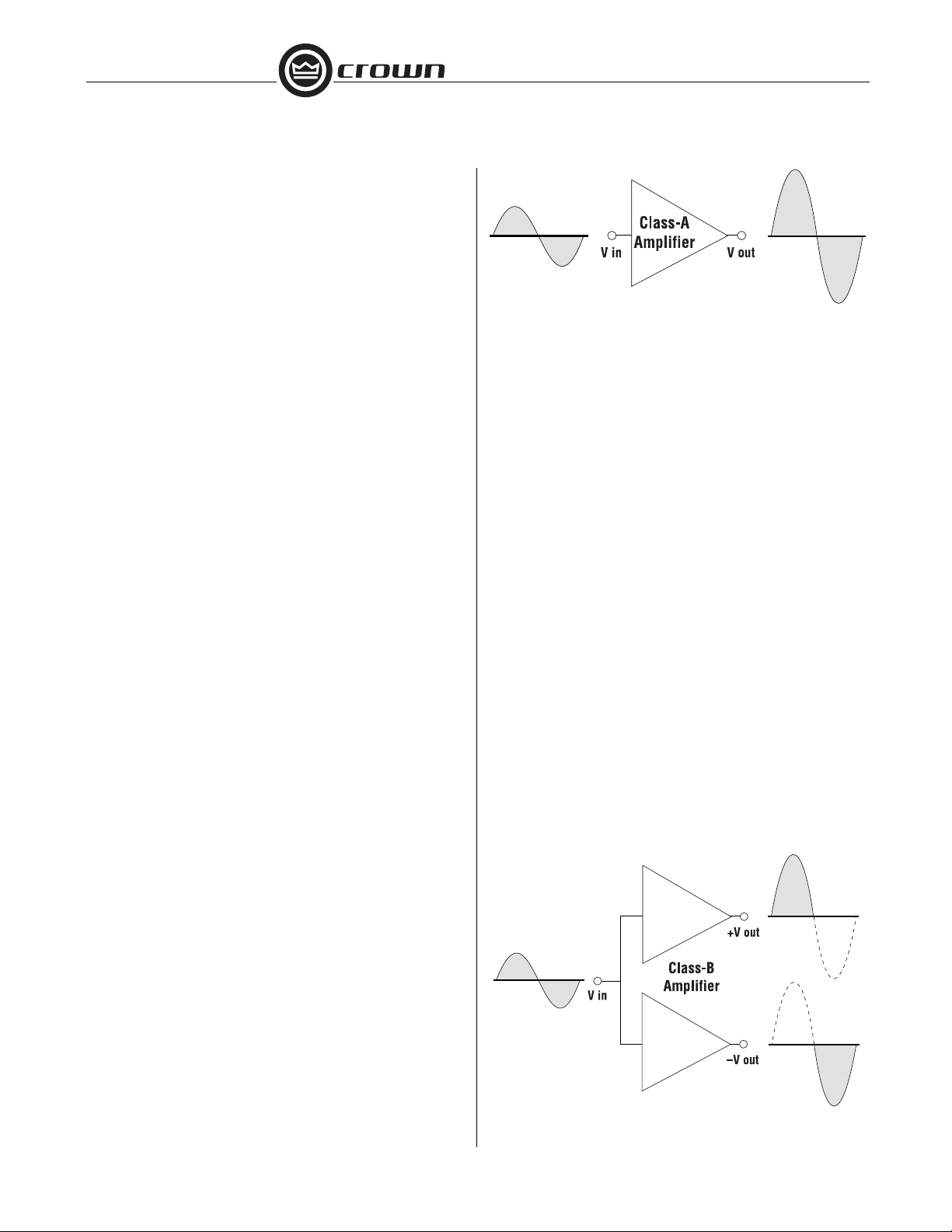
CLASS-A
Class-A amplifiers are the simplest in design, and can
be the most distortion-free of all amplifier classes. In
class-A, the output devices are biased on all the time
with a current large enough to produce the largest
output signal.
CLASS-B AND TIME ALTERNATION
Class-B was invented as a solution to the efficiency
problem with class-A. The invention of class-B is significant in that with it came the concept of time alternation,
which has been the foundation of virtually all power
amplifier designs used for audio reproduction and industrial power since about 1931 to the present. While
many incremental improvements have been brought to
market since that time, none have varied from the basic
time-alternation paradigm.
The basic class-B amplifier implements two devices in
the output stage in a “push-pull” arrangement, with each
amplifying half of the waveform, and the devices operate in strict time alternation. When the signal goes
positive, the positive device conducts while the negative
Some class-A amplifiers may employ both a positive
and negative device in a push-pull arrangement to
increase output power, but both devices still are biased
Class-B Operation
Page 2
The Class-I Amplifier
device is biased off. In turn, when the signal goes
negative, the positive device biases off while the negative device turns on and conducts the negative portion
of the signal.
This configuration provides much greater efficiency
than class-A. The problem with class-B is that it can
create distortion at the zero-crossing point of the waveform, making it unsuitable for precision amplifier applications. Improvements to and variations of class-B have
been developed to solve the crossover-distortion problem, and many are in common use today; however, all
operate under the push-pull and time-alternation paradigms.
All amplifier classes have theoretical limits to their efficiency, meaning they all waste a portion of the energy
they draw from the AC mains supply. Dissipative designs such as class-A, class-B and other variations,
have theoretical limits well below those of “switching”
designs since they operate in that region between cutoff
and saturation. This lower efficiency may not be a
particular problem with lower power applications; however, it can be a major factor in large amplifiers, and
when several amplifiers are being used in an application. AC mains power may be limited and/or expensive
to supply, and excessive heat created by dissipative
amplifiers can also be inconvenient and costly to deal with.
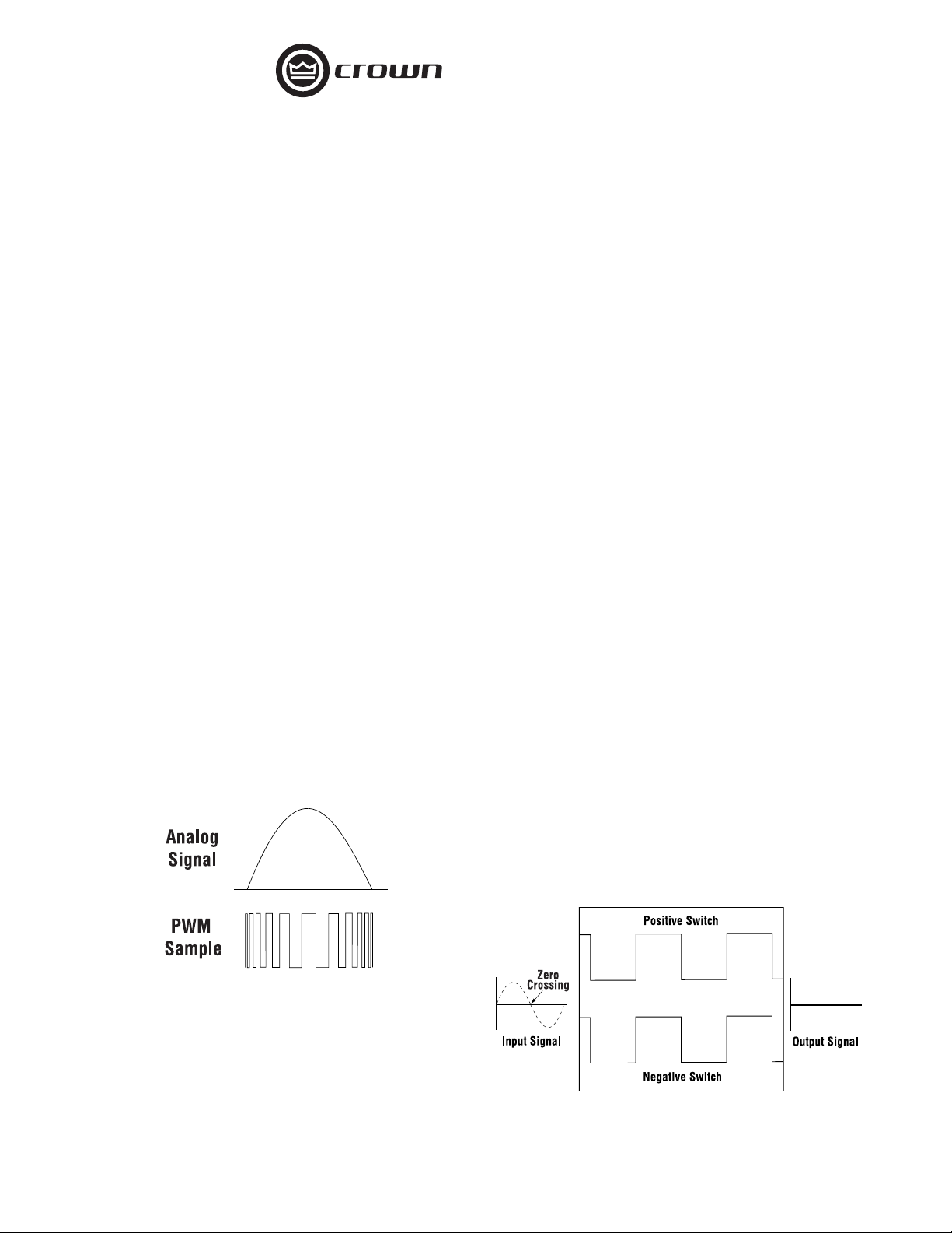
PWM
PWM (Pulse Width Modulation) has been used for years
in non-precision amplifiers to achieve very high efficiency. A PWM converter modulates the analog signal
onto a fixed-frequency carrier wave, creating pulses
THE TIME-ALTERNATION PROBLEM IN PWM
The primary drawback to using previously existing
(class-D) PWM technology in a precision, high-power
audio amplifier output stage has been that in order to
keep distortion sufficiently low, accurate timing circuitry
is absolutely critical. Even the slightest variation in timing
can cause both positive and negative switching devices
to be on at the same time, allowing high “shoot-through”
current to destroy the output circuitry. In essence, the
time-alternation paradigm works well for dissipative
amplifiers, but not so well for switching ones.
Crown invented a highly reliable PWM amplifier output
stage that produces very little audible distortion, and
solves the reliability challenge. This was made possible
by adapting, for the first time in amplifier design, the very
opposite of time alternation.
CLASS-I OPERATION
The push-pull paradigm is part of class-I but the timealternation paradigm is not. In class-I, two sets of
switching output devices are arranged in a “parallel”
fashion and operating balanced in time, with both sets
sampling the same input waveform. One set is dedicated to the positive current portion of the waveform,
and the other to the negative current portion. When there
is no signal applied, or when a signal varying in amplitude reaches the "zero crossing" between positive and
negative, the switching devices are being turned on and
off simultaneously with a 50% duty cycle. The result is
the formation of two balanced and canceling highfrequency output currents with no net output at the nosignal condition. The two output currents are said to be
“interleaved,” and class-I is named from this interleaved
characteristic.
PWM Sampling of an Analog Waveform
that vary in width depending upon the amplitude of the
signal's waveform. This creates a “sampling” of the
signal, which is then converted back to analog to drive
the load. The output devices “switch” between fully on
(saturation) and fully off (cutoff) states, so they waste
very little energy.
To produce a positive output signal, the output of the
positive switching device is increased in duty while the
negative switching device is decreased by the same
Class-I Switches, Signal at Zero Amplitude
Page 3

Dissipative Amplifier
Class-I Amplifier
Reactive Energy
Reactive Energy
The Class-I Amplifier
amount. Class-I uses symmetrical interleaved PWM,
meaning both the leading edges and trailing edges of
the pulse are varied according to the amplitude of the
signal, and the spacing between pulse centers remains
constant. Both the positive and negative switch pulses
remain aligned on-center, and the net output current is
positive.
Class-I Switches, Positive Signal
Likewise, to produce a negative output signal, the
output of the negative switching device is increased in
duty while the positive switching device is decreased by
the same amount. Again, both switch pulses remain
aligned on-center, and the net output current is negative.
tive energy returned from the loudspeaker to the amplifier is reabsorbed and output again to the loudspeaker
with little loss. Non-switching, dissipative amplifiers are
forced to dissipate all of the returned energy and more
in the form of heat. This means class-I amplifiers are
louder than other amplifiers with comparible power
specs, yet they stay much cooler, and can be lighter
since they don’t need nearly as much mass for heat
dissipation.
Reactive Energy Returned to Amplifier
From Loudspeaker
Class-I Switches, Negative Signal
The result of using interleaved PWM is that by operating
the switching devices at 250 kHz, the signal is effectively
modulated at 500 kHz since both the leading and trailing
edges of each pulse contribute to the output ripple
current. This arrangement further increases efficiency,
since switching losses are effectively halved by operating the switching devices at 250 kHz, rather than at 500
kHz as would be necessary with class-D designs to
achieve the same effective sampling of the waveform.
Class-I amplifiers also have all of the nearly ideal power
converter attributes of class-D PWM amplifiers, in that
reactive loudspeaker loads are easily driven. The reac-
With it’s rock-solid reliability, high quality audio reproduction and unmatched efficiency, Crown’s patented
class-I technology creates a totally new paradigm for
amplifier design that represents the future of professional amplifiers.
Crown Audio, Inc.
P.O. Box 1 000
Elkhart, IN 465 15-1000
TEL: 21 9-294-8200
FAX: 21 9-294-8FAX
www.crownaudio.com
Trademark Notice:
®
Crown
and
BCA®
Printed in U.S.A.
are registered trademarks of Cr own International.
137234-1
12/03
 Loading...