

Crown SRP-PET 2 Installation Instructions Manual
1 2 3
345
6
s
s
CROW SCIENTIFIC RESEARCH
SRP-PET 2
TM
PASSIVE INFRARED
INTRUSION DETECTOR
WITH PET UP TO 45LBS IMMUNITY
ELECTRONIC ENGINEERING LTD.
INSTALLATION INSTRUCTIONS
P/N 7101022
4 5 6
SELECTING MOUNTING LOCATION
Choose a location most likely to intercept an
intruder. See detection patterns in figure 5.
The dual-element high quality sensor detects
motion across the beam. It is slightly less
sensitive when detecting motion toward the
detector.
The SRP-PET 2 performs best when provided
with a constant and stable environment.
SRP-PET 2 FEATURES
∗ Immunity to animals up to 45 lbs.
∗ Dual element Pyrosensor.
∗ Hard type full pattern spherical lens.
∗ Variable pulse width adjustment.
∗ Sensitivity adjustment.
∗ Automatic temperature compensation.
∗ Low current compensation.
∗
Height installation (calibration free) from
6ft to 8ft.
∗ Environmental immunity.
∗
High - tech design.
∗ Fully insulated sensor chamber.
∗
Totally sealed sensor chamber.
AVOID THE FOLLOWING LOCATIONS
− Facing direct sunlight.
− Facing areas subject to rapid quick
temperature changes.
− Areas with air ducts or substantial air flows.
The SRP – PET 2 provide immunity to
45lbs pet active bellow 3 ft.
For better immunity, avoid installation in
area reached by pet.
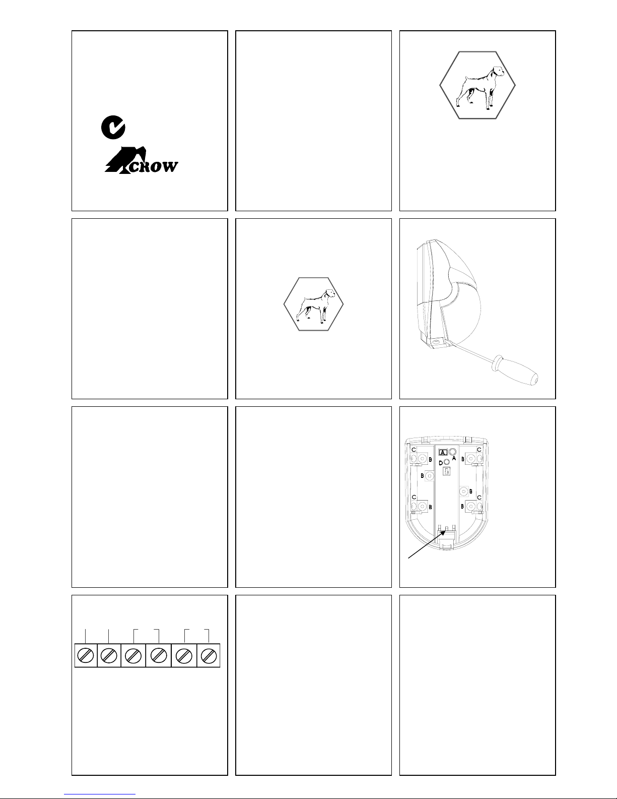
FIG. 1 - REMOVAL OF FRONT COVER
7 8 9
1. To remove the front cover, insert a flat
screwdriver in the slot between the front and
the bottom, above the holding screw hole and
push gently, until the front cover is
disengaged and the opening click is heard
(Fig 1.).
2. To remove the PC board, carefully loosen
the holding screw located on the PC board.
3. Break out the desired holes for proper wiring
as per fig 2.
4. Insert the wire through the wire access hole,
and mount the detector base to the wall,
corner or ceiling with the necessary number
of screws and the suitable bracket.
10 11 12
FIG. 3 - TERMINAL BLOCK
12VDC
-
+
RELAY
NC
12
NOTES for UL referring countries
1. Connect the SRP-PET 2 to a “ U.L. ”
listed burglar alarm Power Supply or
control panel capable of providing
standby power for at least four (4) hours.
2. Refer to national electric code, NFPA-70
for wiring methods.
3. The SRP-PET 2 production batch can be
identified by the 4 digits printed on the
terminal strip side of the PC board.
TAMP ER
MOUNTING THE DETECTOR
For PET immunity mount flat on the wall or in the
corner.
It is recommended to mount the detector
between 7ft and 8ft for optimal coverage, and
pet immunity.
5. Reinstall the PC board, set it a low as
6. Access for wiring located on the PCB. See
7. Replace the cover by inserting it back in
possible - till stopper (see fig.2). Tight the
holding screw.
fig 3.
the appropriate closing pin until the closing
click is heard.
TERMINAL BLOCK CONNECTIONS
Run the cable through the cable entry hole and
connect the wires in accordance with the
NC
following instructions:
Terminal 1 - Marked - ( - 12V )
Connect to the negative Voltage output or
ground of the control panel.
Terminal 2 - Marked + ( + 12V )
Connect to a positive Voltage output of 7.8-16
Vdc source (usually from the alarm control unit)
Terminals 3 & 4 - Marked RELAY
These are the output relay contacts of the
detector. Connect to a normally closed zone in
the control panel.
Terminals 5 & 6 - Marked TAMPER
If a Tamper function is required connect these
terminals to a 24hour normally closed protective
zone in the control unit. If the front cover of the
detector is opened, an immediate alarm signal
will be sent to the control unit.
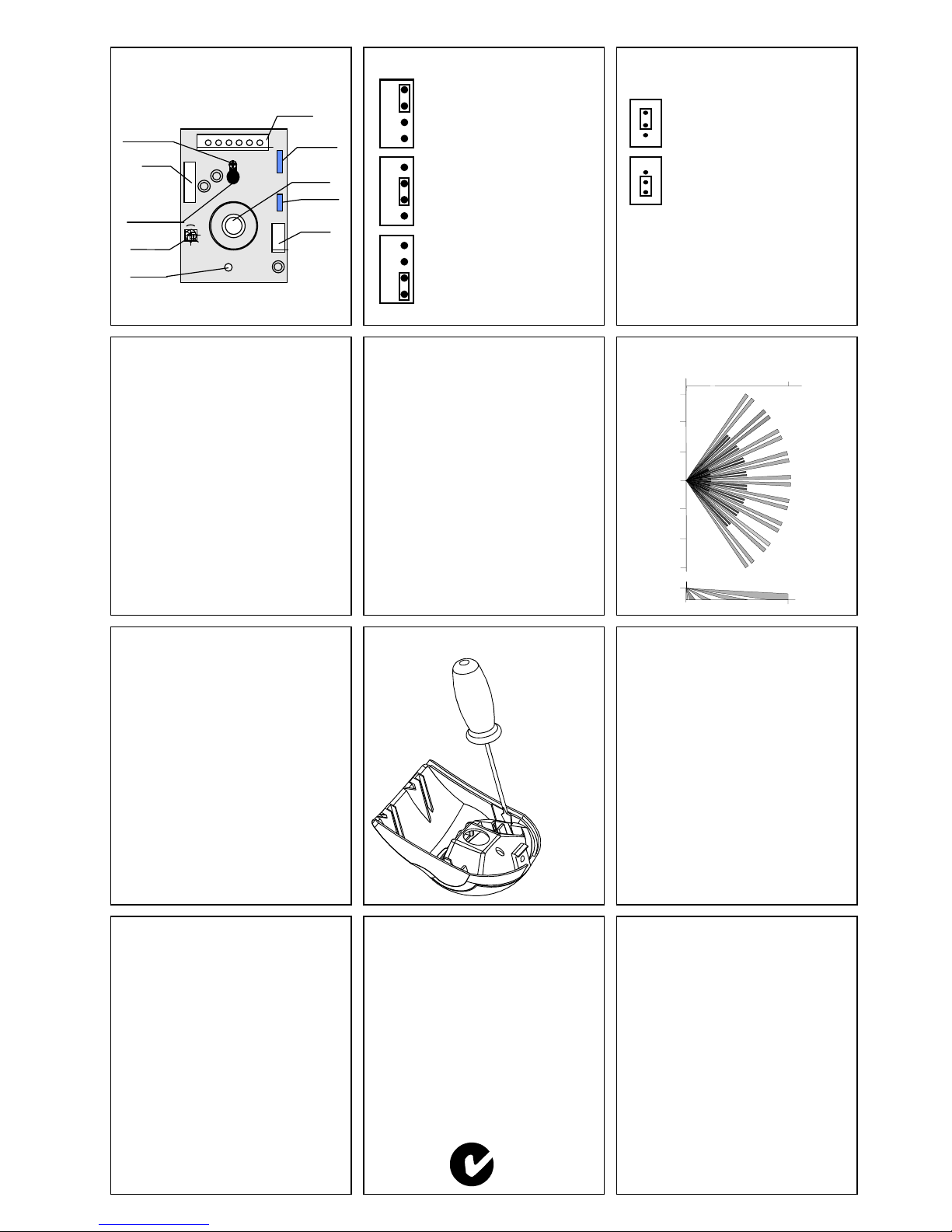
FIG. 2 - KNOCKOUT HOLES
Wires access
A.
hole (2).
Flat wall
B.
mounting hole
(2 or 4).
Corner
C.
mounting hole
(2 or 4).
Bracket
D.
mounting hole
(1).
Stopper pins for PCB
WIRE SIZE REQUIREMENTS
Use #22 AWG (0.5 mm) or wires with a larger
diameter. Use the following table to determine
required wire gauge (diameter) and length of
wire between the detector and the control panel.
Wire Length m 200 300 400 800
Wire Diameter mm .5 .75 1.0 1.5
Wire Length ft. 800 1200 2000 3400
Wire Gauge # 22 20 18 16
13 14 15
FIG. 4 - PCB LAYOUT
HOLDING SCREW
RELAY
PCB MOUNTING
HOLE
SENSITIVITY
ADJUSTMENT
-+
LED
16 17 18
LENSES-INTERCHANGEABLE HARD
TYPE SPHERICAL LENSES PATTERN
COVERAGE WIDE
ANGLE
105°
18m x 10m
___________________________________ ___________________
TOTAL
DETECTION 52
ZONES
TERMINAL
BLOCK
JUMPER
PULSE
PIROSENSOR
TAMPER
JUMPER
LED
PULSE WIDTH JUMPER SETTINGS
Jumper on No. 1
1
This setting is for a stable
2
environment without air
3
drafts.
Jumper on No. 2
1
This setting is for operation
2
within a normal environment.
3
Jumper on No. 3
1
This setting is for operation
2
within a harsh environm ent.
3
NOTE:
DETECTION RANGES ARE SPECIFIED AT 20° C
(68° F) AMBIENT TEMPERATURE.
LED ENABLE JUMPER SETTING
Connect a jumper between the marked terminals
to enable or disable the LED (ON or OFF).
Led ON
Led ON
Led OFF
SENSITIVITY ADJUSTMENT
The sensitivity potentiometer should be adjusted
according to the security risk level at the
installation site.
For high-risk locations, the sensitivity should be
adjusted close to MIN. In low risk situations, the
sensitivity should be adjusted closer to MAX
factory set to MIDDLE.
Always walk test and re-adjust if required.
FIG. 5 - WIDE ANGLE LENS PATTERN.
TOP VIEW
25ft
16ft
8ft
0 ft
33ft
19 20 21
CHANGING THE LENS
1. Remove the front cover by inserting a flat
screw driver in the appropriate slot.
2. Using a small flat screwdriver, press on
left or right side of the installed lens which
will then pop out from its side right and
left holding pins.
3. Select the desired lens and hold it while
making sure its upper holding pin is
pointed upwards.
4. Snap the lens to its place by pressing
again from outside of the front cover until
a click is heard, confirming the new lens
is tightly inserted. See fig 6.
5. Replace front cover.
22 23 24
TECHNICAL SPECIFICATIONS
MODEL SRP-PET2
Detection Method Dual element PIR
Power Input 7.8 to 16 VDC
Current Draw Standby: 14mA
Active with LED: 8mA
Active w/o LED: 5mA
Temperature
Compensation YES
Pulse Width Adjustable
Alarm Period 2 +/-1 sec
Alarm Output N.C 28VDC 0.1 A with 10 Ohm series
protection resistor
Tamper Switch N.C 28VDC 0.1A with 10 Ohm series
protection r esistor - open when cover
is removed
Warm Up Period 60 sec
LED Indicator Led is ON during alarm
Operating Temperature -20
RFI Protection 30V/m 10 - 1000MHz
EMI Protection 50,000V of electrical interference from
lighting or power through
Dimensions 95mm x 70mm x 58mm(3.8”x2.8”x2.3”)
Weight 85 gr ( 3 oz )
C to +60°C(-4°F to +140°F)
°
Crow reserves the rights to change
specifications without prior notice
3502203b
FIG. 6 REPLACING THE LENS
CROW LIMITED WARRANTY
(Crow) warrants this product to be free from defects in materials and workmanship under normal
use and service for a period of one year from the last day of the week and year whose numbers
are printeon theprinted circuit board inside this product.
Crow’s obligation is limited to repairing or replac ing this product, at its option, free of charge for
materials or labor, if it is proved to be defective in materials or workmanship under normal use
and service. Crow shall have no obligation under this Limited Warranty or otherwise if the
product is altered or improperly repaired or serviced by anyone other then Crow.
There are no warranties, expressed or implied, of merchantability or fitness for a
particular purpose or ot herwise, which extend beyond the description on the face
hereof. In no case shall Crow b e liable to anyone for any consequentia l or incidental
damages for breach of this or a ny other warranty, expressed or implied, or upon any
other basis of liability whats oever, even if the loss or damage is caused by Crow’s own
negligence or fault.
Crow does not represent that this product can not be compromised or circumvented; that this
product will prevent any person injury or property loss or damage by burglary, robbery, fire or
otherwise; or that this product will in all cases provide adequate warning or protection. Purchaser
understands that a properly installed and maintained product can only reduce the risk of
burglary, robbery or other events occurring without providing an alarm, but it is not insurance or a
guarantee that such will not occur or that there will be no personal injury or property loss or
damage as a result. Consequently, Crow shall have no liability for any personal injury, property
damage or any other loss based on claim that this product failed to give any warning. However, if
Crow is held liable, whether directly or indirect-ly, for any loss or damage arising under this limited warranty or otherwise, regardless of cause or origin, Crow’s maximum liability shall not in any
case exceed the purchase price of this product, which shall be the complete and exclusive
remedy against Crow.
N345
8ft
16ft
25ft
7ft
SIDE VIEW
TEST PROCEDURES.
WAIT ONEMINUTE WARM-UP TIME AFTER
APPLYING 12 VDC POWER. CONDUCT
TESTING WITH THE PROTECTED AREA
CLEARED OF ALL PEOPLE.
Walk test
1. Remove front cover.
2. Replace the front cover.
3. Start walking slowly across the detection
4. Observe that the detector’s led lights
5. After the walk test is completed, the led may
6.
NOTE:
Walk-tests should be conducted, at least once a
year, to confirm proper operation and coverage of
the detector.
CROW ELECTRONIC ENGINEERING LTD.
ISRAEL
Tel: 97 2-3-5569937 /8 /9
Fax: 972-3-5 592981
USA
Fort Lee , N.J. 07024
Tel: 1-800 -GET CROW
or (20 1) 944 0005
Fax: (201) 944 1199
AUSTRAL IA
Tel: 6 1-3-9596 7222
Fax: 61-3-9 596 0888
UK:
W idbrook Bradford on Avon
W iltshire BA15 1UD
Tel: 0 1225 863 138
Fax: 01225 863 171
POLAND:
Ul. Leszno 34 /36
Tel: 4 8 22 632 9666
Fax: 48 2 2 632 5543
These instructions supersede all previous issues
The pulse jumper must be in position 3. The
led must be enabled.
zone.
whenever motion is detected.
be disabled.
Allow 5 sec. between each test for the
detector to stabilize.
: 57 Hamelacha St., Holon Israel
E-MAIL : support@crow.co.il
: 2160 North Central Road,
: 429 Nepean HWY Brighton East Vic 3187
crow@crowaust.com.au
E-mail:
Unit 5, Bradford on Avon Marina
VIDICON 01-199 Warsaw
vidicon@medianet.com.p l
E-mail:
in circulation prior to Feb. 1999.
33ft
 Loading...