

Page 1
PROFESSIONAL
STUDlO
AMPLIFIERS
Studio
O
"99
8by
8000.
Reference'*
&"i.PF
respeclive
Crown
Sfudio
are
registered
owrwrs.
Referenc
Some
models
Ir~ternatit:,nal,
Refere?-9c:c awplifiers
and
Gronnd~d
&!.idge7"
trademarks
fnc.,
may
P.O.
are
are
trf
Crcwn
be
exported under
Box
t
COO,
produced
tradcrnarks
Elkhart.
by
and
BntsrnationaY,
lndizn~i
Crawn
Amcnm:'@
Irx.
dio
Referenee
the
name
46575-?OQO
fnterrsaticsnal,
&IrcswsT
Blher
trademarks
Asrr@rou@
U.S.A.
Inc,
xr'radernark
10C?
ODEP
are
Telephone:
Notice:
IQ
S,ysl'cm.e"
the
properv
219-244-
Skrdio
and
of
their
Page 2
@Krawn"
--,,,
The
information
the
equipment.
maintenance.
Technical
if
Suppart
furnished
Nor
does
you
need
Group,
Sbippin-ag:
in
this
it
cover
special
Stlidio
manual
every
assistance
Mai/:
P.0.
Pit.
2
S,W,,
Phone:
Refgrence
, , ,
.-.
does
not
Include
possible
beyond
BQX
4008
171
8
$800)
342-6939/(2
FAX:
Web:
~w~cPQw~~u~~~~co~
Service
all
8itua"ii~n
the scope
Elkhart
W,
Mishawaka
$2
"19)
294-8361
-""...""
of
the
which
lN
1
9)
Rd.,
294-8206
Manual
de"iaifs
465?5-1000
may
of
this
Elkhark
sf
design,
ariss
manuas,
production,
during
please
EN
4651
installation,
7
or
eontact
R~K
*-....-
variations
operation
the
Crown
6
of
sr
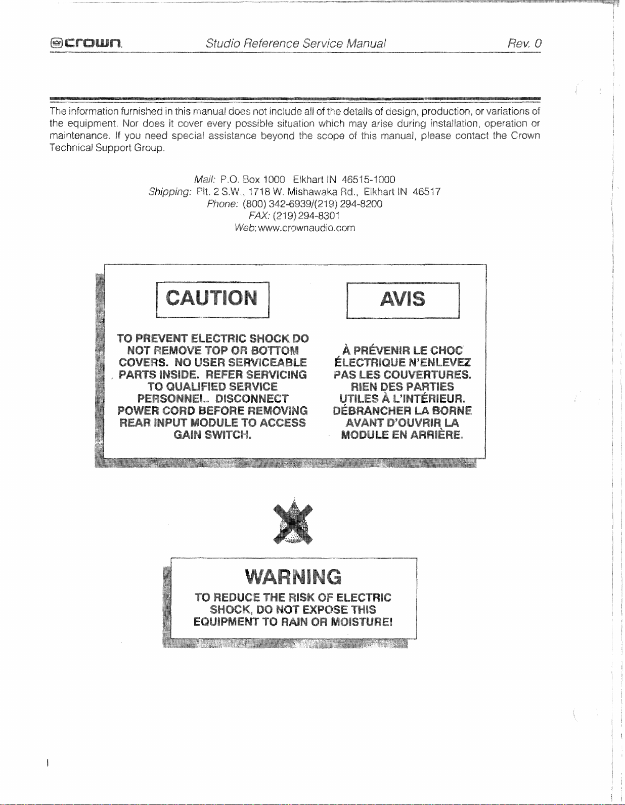
TO
PREVEMT
NQT
REMOVE
COMERS.
.
PARTS INSIDE,
NQ
TO
QUALIFIED
PERSOMNEL*
POWER
RmR
CORD
ENPUT
GAIN
ELECTRlC
TOP
SMOCK
OR
BQnDM
80
USER SERVICWBLE
REFER
SERVOCtNC
SERVICE
DISCONNECT
BEFORE
MODULE
SWITCH,
f
0
REDUCE
SHOCK,
EQUIPMENT
REMOVING
TO
ACCESS
THE
RISK
DO
NOT
TO
RAIN
A
PR~VENIR
~LECTRIOUE
PA8
LES
RlEM
UTlLES A L"INT~RIEUR,
D~BRANCHER
AVANT
MODULE
OF
ELECTRIC
EXPOSE
OR
THlS
MOISTURE!
LE
CHOG
N'ENLEVU
CQUVERTURES,
DES
PART
lES
u
BORNE
DWUVRIR
EN
ARRI~RE.
U
Page 3

Rev.
Q
12-98
Initial Printing
Page 4

This
page
intentionally
left
blank
Page 5
Rev
-
8
.
.-
1
Bntroductisn
1.
1
The
1.2
Scope
1.3
Warranty
2
Specifications
2 . "Berformance
2.2
Pswei
23
Cantrofs
2.
4
f
ndicators
2.5
l~putsautput
2.6
Output
22
Protcctisn
2.8
Construction
3
Va1tags
4
Circuit
Conversion
Theory
4.1
Overview
4.2
Features
4.3
Frant
4.3.1
4.3.2
4.3.3
4. 4
Voltage
4.4.1
4.4.2
4.5
Grounded
4.5.
Wigh
4.5.2
4.6
Output
4.7
Ganliol
4.7.1
4.
7.2
4.7.3
4.7. 4 Fan
4.8
Power
4.8.
1
423.2
4.8. 3 Over
4.9
Display
4.9.1
4"9+2
433
Studio
...................................................................................................
Stndis
Referents
................................................................................................
............................
................................................................................................
.................................................................................................
.............................................................................................
..........................................................................................
Signal
..........................................................................................
........................................................................................
.................................................................................................
...........................................................................................
.............................................................................................
End
Operation
Balanced
Variable
Error
Amp
Amplification
Voltage
bast
Voltage
Bridge
Side
Law
Side
Device
Circuitry
DC$LF
fault
Turn
AC
Soft
Protect
Circuit
On
Corjtrol
Supply
kine
Start
Voltage
Circuitry
............................................................................................
1QC
ODEP
Signal
........................................................................................
Indicafis~s
Reference
........................................................................
...................................................................................... 2.
Service
.~.~~~~~...~.~..A~~~~~....,.........
Manu3l
@crown
3-1
1-1
1-1
1-1
-2-1
1
2-1
2-2
2.2
......................................................................................
.....................................................................................
......................................................................................
..........................................................................
Gnin
Stage
Gain
Stage
(BGS)
(VGS)
.....................................................
........................................................
..................................................................................
.........................................................................
Transfators
Topology
(HS)
(LS)
Emulation
................................................................................
....................................................................
Amplifiers
.........................................................................
............................................................................
(LVAS)
...............................................................
Prccalectian
..................................................
(OBEP)
....................................
............................................................................
...............................................................................
Belay
...........................................................................
................................................................................
....................................................................................
Fiiter
............................................................................
...................................................................................
Protection
............................................................
..............................................................................
........................................................................
2-3
2-3
2.3
2.3
3-1
4-4
4-1
4-2
4-2
4-2
4-2
4.2
4-2
4.3
4-3
4-4
-4-4
4.4
4-5
4-6
4-6
4-6
4-6
4-6
4-6
4-6
4-6
4-7
"4-7
4-7
4.7
4.7
Page 6
5
Electrical Checkout
51
General
52
Standard
53
DC
Offset
5.4
Output
55
OBEP
5.6
AC
Pawer
5.7
High
5-8
Common
5.9
Voltage
533
Level
5.
1
1
Current
512
Slew
.
5
f
3
Crosstalk
5.
1-4
Output
5.1
5
Reactive Loads
5.
16
ODEP
5%
17
Mute
5.
18
Law
5.
19
Signal
5.20
Intermadulation
5.21
LED
5.22
Display
5.23
Turn-On
5.24
Turn-OM
525
Past
6
Schematics
7
Parts
7.
7.2
7.3
7.4
7.5
7.6
Figure
Figure
Figure
Figure
Fi%jure
Figt,i
Figure
....................................................................................................
Information
1
General
Standard
Ordering
Shipment
Terms
Illustrated
7.1
7.2
7.3
7.
4
7.5
re
7%
7.
7
...........................................................................................................
and
Adjustment
Informatiow
Initiat
...........................................................................
Conditions
..........................................................................................
Bias
Adjustmen$
Voltage
tine
Gain
Controls
Rate
Adjustment
Draw
.................................................................................
Gutsue
Mode
................................................................................
Wejects'sn
......................................................................................
.................................................................................
bimi
"r
....
...............................................................................
and
*a
OK
Square
..........*<."...........................................................................
Power
...................................................................................
................................................................................
Limiting
and
Frequency
to
Functions
Set-Up
Transients
Transiep-rts
Testing
.................................................................................
Turn-On
Noise
Delay
Protection
Ratia
Diskoflion
.................................................................................
................................................................................
...........................................................................
..........................................................................
.....................................................................................
Procedures
................................................................
....................................................................
.................................................................
,,,
.......................................
5-1
5-1
5-1
5-1
5-1
5-1
5-1
5-1
..................................................................
5-1
5-2
5-2
5-2
Wave
....................................................
5-2
5-3
5-9
5-3
5-4
..................................................................
...............................................................
.......................................................................
...............................................................
5-4
5-4
545
5-5
5-5
5-5
5-5
5-5
5-5
6-1
............................................................................................
lnfarmation
and
Parts
....................
...........................................................................
Special
Parts
...............................................................
...................................................................................
.....,.
........................................................
.................................................................................................
Parts
Front
Panel
Top
Main
Bottom
Back
Output
Main
Pans[
Assembly
Capacitor
PIP
Cage
List
.......................
Exploded
Assembly
Assembly
Assembly
Exploded
Assembly
Assembly
View
Exploded
Exploded
Exploded
Exploded
Exploded
..
.,
,.,,
...................
View
View
View
View
View
................................
.........................
,..
......................................
View
................................
.......
.,
........................
.......................................
...................................
...................................
7-1
7-1
7-1
7-1
7-1
7-7
7-1
7-2
7-4
7-6
7-8
3-1
61
7-12?
7-15
.......
"
Page 7
R@K
.
0
-..,
_____ylll~1~1111__
8
Module
information
8.1
General
8.2
Studia
8.3
Studio
8-4
Q.4397
85
Q43369-0
8.6
Q43183A3
8.7
Q43.450-8
8.8
843584-2
8.9
a4301
8.1
Q
64331
8.1
1
Q43388-0
8.
t
2
Q43389-8
8.13
a4331
.
, ,
information
Reference
Reference
1-6
Main
Outp&r"lodeelie
Control
Control
8-3
Display
1-2
2-0
Stvd8"~
........................................................................................
Control
Main
Main
Butput Module
Display
Reference
Service
Manuai
P,
,,
...........................................................................
1
Module
If
Module
Module
Module
Module
Module
Modu8e
Module
Module
lnfsrmatisn
Infsrmatisn
........................
..................................................................
.............................................
............................................
...
..
,
..................................
..............................................................
...............................................................
...............................................................
...............................................................
.................................................................
...................
....
..,,..
,.,
.............
..............................................................
Module
.............................................................
@CrQWne
8-4
8-4
8-1
8-1
$3-2
8-8
8-11
8-14
8-17
8-20
8-23
8-28
8-33
8-36
P
.................................................
Page 8

@crowne
P
Figure
Figuss
Figure
Figure
Figure
Figure
Figure
figure
Figure
Figure
Figure
Figure
Figure
Figure
Figure
Figure
Figure
Figure
Figure
Figure
Figure
Figure
Figure
Figure
Figuse
Figuw
Figure 8.7
figure
Figure 83
Figurs
-.."..
2.1
3.1
32
4
4.2
43
5.
5-2
53
5.
5.
56
5-4
7.
4.
7.3
7.
75
73
72
8.
8.2
823
8.4
825
8. 6 64381
8.8
8'16
.......-
Studio
Specific
Circuit
.
t
Simplified
Simplified
Simpfified
1
Differentiatar
Differentiated
10
4
inductive
5
5~nd~etive
Tartup@
OBEP
1
Front
2 Top
Bottom
4
Back
Output
Capacitor
PIP
1
a43371
Q43363-8
Q43383A3
Q843458-8
Q4J5Q4-2
a4336
843388-0
043389-8
Q43312-0
Studio
, , , ,
Wefsrence
Voltage
Breaker Selection
Studio
Ampiitier
Grounded
kHz
Square
Load
Load
Yest
Waveform
Limiting
Panel
Parts
Main
Assembly
Main
Panel
Assembly
Assembly
Asssmbly
Cage Assembly Parts
-6
Main
Output
Control
Control
Control
8-3
Bispray
1-2
Main
Main
Output
Display
Reference
Dimensions
Wiring
Refereilea
Front
Bridge
Circuit
........................................................................
Square
Wave
CoId
........................................................................
Warm
...................................................................
Wave
...................
......................................................................
Service
pw
P
Manusf
.........................................................
......
.............,...
Biock
Diagram
End
and
Voltage
...................
..............................
...
......................................
...................................
Ampiifiication
,.....
..............................
..,,,,..*+.+'.........
................................................
Stages
.....................................................................
Waveform
.....................................................................
.............................................................................
Parts
................................................................
Assembly
Msdule
Module
Module
Parts
Parts
Par&
...................
Parts
Map
Module
Maduis
Madula
Module
Module
Mag
Map
Modube
Msduls
.......................
....................
,.
..................................
.........
........................
........................................
............................................................
.............................................................
..........................................................
Map
.....................................................
Map
....................................................
Map
.....................................................
Map
.....................................................
Map
.....................................................
....................
......
..............................
........................................................
Map
.....................................................
Map
..................................................
2-3
3-1
3-11
4-1
..
4-3
4-5
5-2
5-2
5-2
5-3
5-3
5-4
5-4
7-2
7-4
7-6
7-8
7-16
F.12
7-14
8-7
8-18
8-13
8-16
8-19
8-22
8-27
8-32
8-35
8-38
R~K
0
P
Page 9
t
.I
Ths
Studia
The
Studio
Crown
production
Internatfsna\.
reproducing
monic
and
transfer
damping
speaker
1.2
This
Studio
be used
ever,
Servica
readily
This
sectiians
Circuit
Module
function in
factor
motion
Scape
massr_eaI
Reference
with
some
Manual
availabls.
Service
include
Thssry?
Information,
Referenee
Reference
with
a
20-bit
intermodulation
control
contains
the
important
in
Manual
EEfectrieal
amplifiers
They oRsr
dynamic
digital
the
business.
af
20,000
for
sewice
power
amplifiers..
appilcable
information
case
the
includes
Sp~cifications,
Che~kout,
aod
are
the
best
range
capable
recardings.
dis$or$ion
And
detivsrs
a
tight
and
information
Reference
is
duplicated
Reference
severaB
Vottag~
Parts
Exploded
the
flagship
in
sound
of
accurately
Super
provides
the
ultra-high
superior
clean
for
the
It
ia
designed
Manual'
Manual
sections,
Conversion,
Information,
View
Drawings,
sf
re-
low
har-
the
best
foud-
low-end.
Grown
I~P
How-
in
this
is
not
These
Schematics
prised
instal!@d.
cuiQ
boards.
CAUTIOH:
ossd
by
1.3
Warranty
Each
Reference
fated
to
that
this
snl
y
by
most
Crawn
ciud~ng
aft
warranty
Factory
are
included.
a$
the
circuit
Crown
TRs
an
%he
ssrviee
properly
does
infermatien
exparlenc%d
Manual
customer.
dacumentalisn
trained
products
round
trip
service
or
Authorized
applicabls Owner's
the
iocation
or
to
obtain
Service,
Group
Importgr
QI
instructions
piease
(within
(outside
the
contact
North
North
Note
board
with
not
sell
in
this
t@~hnlclaa
contains
In
addition,
service
carry
a
shipping
should
Warran&
Manual
nEarsst
for
Authorired
fcar
tho
Crown
Amerrca)
America),
that
the
blank
(unpopulated)
manual
only
basic
it
is
meant
personnel.
3
Year
within
the
be
referred
Sewice
warranty
receiving
Technical
or
your
a
Mexdu%e
component
Is
h
should
Full
United
Center.
details,
Sarvice
Crown
is
Intsndsd
pslieies
Warranty
to
as
be
staked
ts
be
Because
States),
the
Crown
See
To
Center,
Factory
com-
parts
to
used
find
Support
Crown/Amcrg;bn
cis=.
b~
re-
(in-
the
171
Elkhaa,
Phone:
Tall
FM:
Web:
Plant 2 S.W,
8
W.
Mishawaka
IN
USA
(21
9) 294-8200
Free:
(8QO)
M2-6939
(21
9)
294-8301
.er~wnaudis~com
Bd,
4651
'7
Introduction
t
-7
Page 10

Sf
~dio
This
Reference
pa@@
intentionally
Service
left
Manual
blank
introduction
4
-2
Page 11
The
following
Mode,
26dB,
with
banless
specifications
an
8
Ohm
stherwise
load,
a
specified.
Studio
Referenee
Service
on
ted
rising
tinearly
,Msnual
Bode
Wajsctlon
full
bandwidth
Is
better
[CMR):
than
Better
power
79
from
dB
at
than
20
20
100
Hz
to
kb4z,
dB
480
be-
Hz,
Low-.DJ&o~P@@
age
power
Sta~d~rB
pswer
in
Full
B~nd~idth
pawer
and
2,l
in
noise.
PeHormsnee
Ftgquency
1
watt.
Phase
R~$pon%@:
kHz
at
3
8ignai-to-noise:
full
bandwidth
Tat@!
Harmonic
rated
low-distortion
rated
full
lntsrmoduEIaZlon
Studio
--*
bandwidth
8.025%
Studio
bandwidth
0.025%
Damping
280
Hz,
Crosstalk:
Sb~di~
245
Hz
70
dB
20
ME
65
dB
t
kHz
in
watts
1
kHz
Power:
watts
at
I
Pawer;
watts
from
Response::
+5
w~tt~
(A-weighted)
Dldsalon
bandwidth
Qiatagian
R~f~rw
power
at
78
milfl~atks~
Ref-
power
at
36
mtliiwatts,
Factar:
and
(At
Refer-
ta
at
to
at
Greater
greater
rated
100
Hz,
20
kHz,
f
66
Hz,
20
kHz,
Psaar:
at
1
kHz
Refers
kHz
with
Refers
20
Hm
~8,MdB
to
-75
powerh
I
kHz
power,
Less
to
78
Less
ta
36
than
than
full
bandwidth
Batter
falling
Betdef
falling
Refers
with
8.1 % TkJD
to
26
from
degrees
reater
rcater
(TWO):
pswer.
{IMDf:
than
watts
than
watts
20,000
2,568
than
linearly
tinearly
to
0.02%
ts
maximum
to
maximum
kHz
20
from
than
than
Less
Less
(60
Ha
0,005%
rising
0.005%
rising
from
at
1
kHz.
power,)
106
to
khan
180
to
maximum
THO
and
avsrage
and
noise,
average
with
0.1%
Hs
to
20
kHz
20
Hz
120
dB
belaw
1
3
7
dB
below
than
0,02%
than
0.1%
& 7 kklz
from full
linearly
from
lineariy
dB
better
better
"B
from
than
dB
from
than
$a
BHZ
aver-
noise..
THB
at
ta
26
a4
af
4:
2)
to
;Bull
to
Voltage
put,)
~0~25
2,2
Ps~er
tsw-Di%tofllsn
G~in::
(With
At
the
26
dB,
Studio
m,n,&z;eL
'I
63:
1
k
12%
sensitfvity,
Studio-
-
69:kj
38.1
pa we^
Bandwidth:
&,df-rence6:
and
and
Sf
udio
....
$t~?rea
B~idge-Mono
P8~3I/e/-Msn0
57:
..-.
2%
aor
~12%or32dB~1
-3
dB
from
--3
dB
from
f
kHz
Rcf@rea&
Made
1,160
watts
768
watts
2,228
watts
1,580
watts
2,37
5
watts
1,565
watts
m,,B@-
Stereo Mode
555
watts
355
watts
Bridge-Mono
"i
1
10
watts
71
5
watts
Parab/e/*!dons
1,115
watts
730
watts
Isvel
dB
garn
or
40
1 k 12%
37
dB
(At
standard
3
2.3
Butput
with
per
mode:
into
into
into 4 ohms.
with
per channel
per
mods:
into
into
into
inta
controls
setting,
At
0.775
dB
.-
1
dB;
or
35
At
0.775
41
dB;
dB.
-^B
dB
Hz
ta
32.8
-1
dB
Hz
to
34.4
Power:
both
per
channel
channel
Into
8
ohms,
16
ohms
mode:
2
ohms,
both
chanilel
8
ohms.
16 ohms.
n~ade:
2
alms.
4
ohms,
set
far
maximum
2Q:h3%
volt
sensitivity?
at
1.4
dB
k
1
dB.
volt
sen%itiviby,
at
"84
volt
1
kHz
power.)
from 5 Mz
kHz.
from
5
Hz
kHz,
cchannsbs
into
4
into
8
chag.gne!s
into
4
into
8
or
volt
sensitivity,
to
27.5
fa
28.6
driven.
ohms,
ohms.
driven:
ohms,
ohms.
ocnt-
26
kHz
kHz
dB
Page 12
Stereo
Bridge-Mono
mode
1,190
800
2,375
1,595
watts
watts
watts
watts
wid)~
both
per
channel
per
chaunef
mode:
inis
8
into
1
~haanneIs
ohms.
6
ohms.
into
iota
driven:
4
ohms.
8
ohms,
Enable:
amplifier
Level:
nel
Stsreomono:
to
A
with
select
A
front
on
front
3
1
dstents,
either
and
panel
A
panel
push
button
off,
rotary
potentiometer
used
$0
CB~~FOI
three-pasitiaw back
Stereo,
Bridge-Mano
used
to
far
each
the
output
panel
switch
or
Parallel-Msns
turn
ehan-
level.
the
used
Par~jIef-Mono
2,350
1,588
St~d8"o Refefcnce
S!W@Q
565
360
Bridge-Mono
3, f 45
720
Par8$/@/-Mono
7,135
"715
Full
Bawdwidth
E@r@o
1,075
768
BrBdge-M~f?~
2,150
"3,535
watts
watts
mode
waus
pea
watts
per
waEs
wakk
into
watts
waE%
Butput
Pewer:
made
watts
watts
per
watts
watts
mode:
into
2
ohms,
into 4 ohms.
H:
wifh
both
cchanne/s
channel
channel
m~d~r
into
8
ohms,
16
ohms
mode:
into
2
ohms.
into
4
ohms,
(20
Hr
wjtfi
both
-lh~aanne/s
per
chanaal
chaalnel
into
8
ohms+
into
f
6
ohms.
into
into
lo
into
ir3Po
drjven:
4
ohms.
8
ohms.
28
kHz)
drivepa:
4
ohms.
8
ohms.
SsnsitivlQ:
partment
ek?annefs:
or
26
dB
voltage
Mater
OnfBff:
pane!
used
Meter
Display
frsnt
panel
panel
meters.
af
the
output
Ground
isslate the
Reset:
the
2,4
Enable:
unit's
Signal::
to
Lift:
A
two-p~~ltion
AC
mains
lndicatars
This
How-voltage
Each
show
audio
A
three-position
used
ta
select
6,795
ai
1.4
gain,
A
tws-position
to
turn
the
Mode:
used
to
set
Display modes
signal
in
A
two-position
irrput
phone
circuit
indicator
power
channel
output.
switch
inside
the
input
sensitivity
volts
for
standard
front
panel
A
twa-position
the
display
dB
or output
back
jack
and
back
panel
switch
meters
switch
mudc
include
levels
panel
AC
{chassis)
switch
behind
dynamic
switch
b~eaker*
shows
the
on/M
supply
has a signal inclicatar
the
P,l,I,p
'I
kHz
on
behind
tor
in
dB.
grounds.
used
status
that
corn-
for
both
pg;aw~r,
the
front
or
off,
ths
front
range
used
fa
roset
of
flashes
the
to
the
$&2dio
Ref-K
St~f-sa
495
340
Brid~e-Mgbf?~
1,020
698
Load
Impedsn~e:
4
ts
8
ohms
Mona made,
Required
240
VA6
AC
(k
idle.
mode
watts
watts
watts
watts into
Safe
in
stereo
and
Mains:
10%)<
2
to
56
Both
wifk
bath
per
channel
per
chaanel
mode:
into 8
16
with
all
mode,
4.
ohms
or
60
units
chhanng!~
into 4 ohms.
into
ohms.
ohms.
types
of
loads,
8
ts
16
ohms
in
ParalteI-Mon~
Hz;
106,
120,
draw
90
watts
db^ven:
8 ohms.
Raked
in
200,
or
far
Bridge-
MO~G,
220
or
less
at
i@C:
Each
channel
the
output
by
0.85%
tion
formance,
Ilght
0DEP:Each
the channel's
LEDs
available.
serve,
waveform
or
indicators
In
stays
an.
channel
are
brigfatly
In
its
indicator
has
an
differs
more.
The
LED$
to provide
Paralfel-Mono
has
an
resewe
the
tit
rare
wisi
energy
to
show
event
dim
18C
indicator
from
act
proof
of
mode
ODEPindieator that
status,
that
that
a
in
proportion
%hat
the
input
as
sensitive
di~f~rtian-free
the
channel
Normally,
reserva
channel
to
flashes
wavsform
if
distsr-
per-
2
/0@
shows
the
energy
has
BDEPlim-
no
is
re-
Page 13
Dynamic
segment
of
(From
namic
%he
As
levels
2.5
input
back
tors
lnput
Pdornina!ly
I~put
for
Output
ing
plugs,
Qutput
2,s
Ranga/Lsuel
meter that
the
output
the
factory, the
range.)
ratio
sf
peak
output
level
are
relative to
llnputlOutput
Csnneetor:
panel
and
on
the factory-installed
impsdanee:
5
K
San%itiuiQ:
standard
Canaeetam:
posts
far
spads
Impsdaase::
micr~henries,
sigrrai
As
to
meters
Two
two
Nominally
ohms,
Settings
1
kHz
Two
each
lugs
Less
Meter:
displays
in
dB
sr
amplifier
dynamic
average
they
standard
balanced
balanced
unbaianced.
include
pswea: or
sets
of
cha~3rrel
si
bare
wire),
than
Each
Channel
either
the
the
output
is
set
range
meters,
power
of
show
how
1
kHz
powerq
'!,is-inch
three-pin
P..B,?-FX,
10
K
ohms,
0,775
26
dB
voleage
color-coded
(for
connecting
10
miBliahms
has
dynamic
love!
to
display
they
tach
high
the
jacks
XLR
balanced
volts
sr
gain.
5-way
in
sarisa
a
five-
range
in
dB,
dy-
show
channel,
~~~lput
an
the
connec-
1
A
volts
bind-
barlana
with
Input:
Input
amplifier
Turn
gerous
2,8
Steel
panel
a
specially
from
CoeiJng:
input
On:
The
turn-on
Constrvctlon
chassis
with
front
to
Convection
overload
to
four
transier~ts,
with
super-glass
designed
side
prstectisn
limit
current.
second
durable
Imron
flaw-through
panels.
cooling
computerized, on-demand
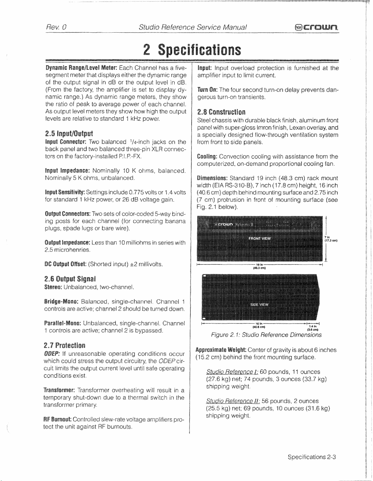
Dimen$ions:
width
(40'6
CM)
(7
em)
Fig.
2.1
Standard
fElA
RS-316-B),
depth
prstrusion
belaw),
behind
in
19
9
inch
mounting
front
is
furnished
~C~TM-Q~
b8ack
finish,
deilay
finish,
aluminum
lexa~,
prevents
ventilation
with
assistance
proportional
inch
(48.3
(17.8
surface
sf
mounting
em)
cm)
height,
cooling
and
surface
at
averiay?
system
from
fan.
rack
mount
16
2.75
the
dam
front
and
the
inch
inch
(sea
DC
Output
8@ssZ;
(Shorted
2.6
Output
Starsa:
Brldgs-Mona:
controis
Parallai-Mono:
"icontmls
2,7
Protection
ODEP:
which
cuit
limits
conditions
Trensformer:
temporary
Signal
Unbalanced,
Balanced,
are active;
Unbalanced,
are
active;
ff
unreasonable
could
stress
the
output
exist.
Transformer
shut-down
transformer primary-
RF
Burnout:
tect
the
Controlled
unit
agairlst
input)
32
twa-channel.
singla-channel.
channel 2 should
single-channel.
channel
the
output circuitry?
current
2
is
operating
level
until
bypassed.
overheating
due
ta
a
ttmerrnal
slew-rate
RF
burnouts,
voltage
millivslts.
Channel
be
turned
Channel
conditions
the
QDEPcir-
safe
operating
will
result
~wifch
amplifiers
f
down.
$~~g;;ur
in
a
1
in
the
pro-
Apprsxlmata
(15.2
shipping
(25.5
shipping
cm)
WaiigM:
behind
weight.
kg)
net;
weight.
Center
the
front
69
pounds,
of
gravity
mounting
60
pounds,
unds,
3
ounces
56
pounds,
"1
is
about
surface.
11
ounces
2
ounces
0ouncss
6
(332
(31
"6
inches
kg)
kg)
Specifications
2-3
Page 14

Studio
Reference
Service
ManuaI
This
page
inten&ianally
/aft
blank
Page 15
Studio
Reference
Service
Manual
The
Studis
VAC?
tion,
transformer
form the
and
3.2
to
order
number
CAUPfO#:
on
gxperisne~d
valtage
1.
Remove
plifier
2,
With
module
Reference
I20
VAG,
This
is
fallowing
ta
convert
the
listed
B~eausa
contlguratiian,
tha
(held
on
the
front
{front
Ampfifiers
200
VAC,
made
for
the
passible
high
pracedure
the
operating
approprate
in
Figure
thare
t~ehnician
tap
cover
by
8
screws).
panel
toward
center)
and
can
220
VAC
or
by
the
energy
power
and
refer
voltage.
circuit
breaker
3.2.
1%
a
risk
of
slsctr!~
ahould
aggmpfk
of
the
Studio
you,
the
tab
connectors
VOCrAGE
be
wired
240
VAC
use
of
supplies.
%s
Figures
YOU
using
sheek,
ts
altgr
Referenee
locate
tka
JUMPER
age
for
100
opera-
a
multitap
Per-
3.3
may
have
the part
sniy
the
line
am-
controt
(upper
Convers
-
right
3,
and
4.
charrges
5.
nections.
6,
side
operating
7,
necessary+
8.
read
side
9,
1
-".-
hand
corner
Cut
and
remsve
wires,
Refer
to
Figure
for
the
lnstaBI
wire
Note
the
of
the
module
line
Refer
"I
Figure
On
the
rear
the
correct
of
the
rear
ReassembHe
of
the
desired
ties
to
frequency.
32
05
$he
valtage.
panel,
the
unit.
WPt
module).
wire
3,1
and
operating
dress
and
change,
and
change
unit,
change
This
just
above
6
ties
make
the
is
to
access
voltage.
wires
switch
if
necessary,
the
?$"re
on
the
the
the
the
appropriate
above
on
the
Circuit
line
cord
lower
serial
jumpers
the
ief2
hand
for
Breaker
tag
right
hand
tag.
con-
the
if
to
Figure
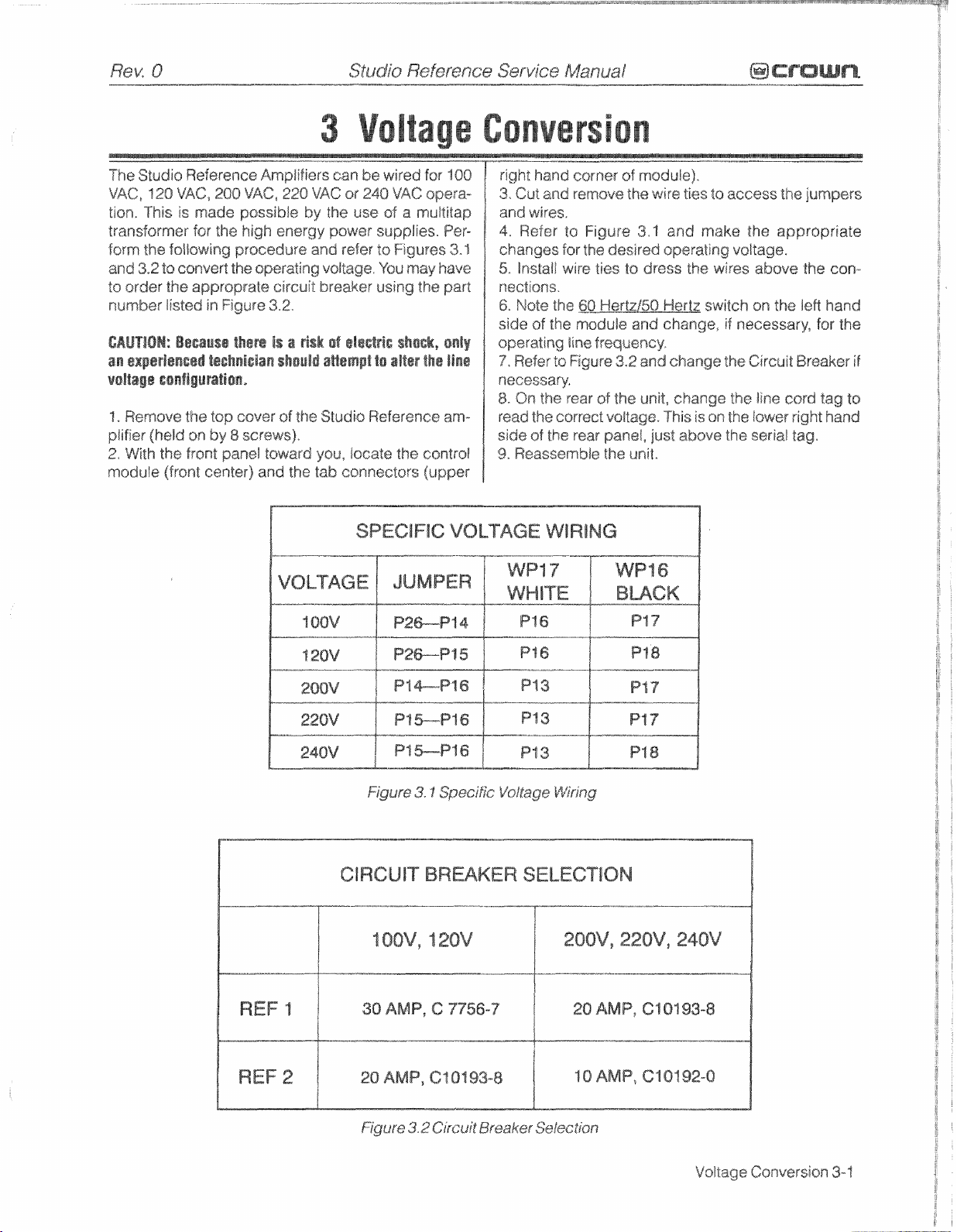
Ct
RCUfT
30
3.1
BREAKER
AMP,
C
Specific
7756-7
Vo1tage
Wifing
SELECTiON
1
20
AMP.
Cl
01
93-8
Page 16

@
crawma
--.,."---
. , .
, " '
Studio
-."...--,
Reference
Service
Manuaf
R@K
.
0
This
page
intentionally
left
blank
Voltage
Conversion
3-2
Page 17
Studio
Reference
Service
Manual
INVERTING
BRIDGE
BWUNCE
LOW
OUTPUT
PNP
STAGE
Circuit
SIDE
Theory
4-1
Page 18
Bcrcrurn.
Studio
innovations, including gf@tuflded
teehnofogies.
essentially air conditianer technology.
lo
across
significantly better emling than
nology
transistors are
plastic case
thermal
ings.
sure
used
ers utilize n~gativa;. feedback
vide
back
damping.
in
feedback,
distortion output tapol~gy~
erence
Fsatt~res
high
varjable
fiffes;
ervodtage and internal fault protection,
fier can operate
as
a)lows seiectian
put.
are
user
presence
the
riel
put
For
or
Referenee amplifiers utilize numerous
Cooling
top, and front to
a
wid@
heatsink.
used
by
of
style.
margin
Ail
devices
maximum
is
negative feedback. Almost
stabifity$
imps
reliability, Another electronic
but
far
maximum
t~chniques
side.
Air
This
many other manufacturers, Output
the
metal can
This
alIo\~s
for
the given voltage
used
are tested
Crown
uses
stability
Studio Reference ampiifiers
@XC$S$
af
20,000
along
in
the bass frequency range.
with
our compensation and
make
amplifier superior*
specific
power
speed,
Soft
start
well
as
in
Level
cnr-llr~ls are mounted
of
the rotary type, Front
know the status
(SP!),
to
the
Studio Reference
toroidal Esansfsrmsr; Computer controlad,
whisper quiet
circuit
Za control inrush curroot;
in either
Dual
sf
and
Bridgge;! or Parallel Mans mode,
(stereo)
made,
input voltage
of
amplifier
distortion
front panel is a five-segmet display Tor each chanwhich
displays
level
in
dB,
addiriauai
ta
the appficable WaFerence Manual,
either
dynamic
details s~fer to the specification section,
Sfudjo Weference
, , ,
bridge
make
ftsws a shafi
type
of air flow pro.\rides
the
"wind
type,
for
a significantly higher
and
--,-..-.-
and
use
Air
flows
$unnel'"tech-
rather
and
current rat-
grad~d to en-
technique
atl
power amplifi-
80
control
multiple
and
gain
nested
greatly
impag>k/ed
have
Grown Studio
include:
fan;
Built
in
AC
This
A
sensitivity
required
on
panel
enable,
(90C),
for
rated &rut-
the front panel and
indicators let
QDEP9
Alsa
included
range
tn
dB
of
damping
Crown
ODEP
what
is
bottom
distance
than
fh~
and pro-
feed-
This
ut"l3-l~~
Ref-
A
power
Fuji
ov-
ampli-
switch
the
signal
on
ar
aut-
two waveforms
condition which,
Signal
Service
Lift
input
amp stage. The
ancsd input
Switch.
is
fed
Manual
-.".-
-
k
to interrupt around
The
non-inverting
to
the
non-hverting
inver"ring
is
fed
to
..,.
"
the
inverting
".,-
-
amp stags. A potentiometer
mod@
rejection adjnmstment
is
at
unity
gain, (From an
this
stage
actually provides
anced signal is
$put
gain
placsd
sf
is
itch,
and
s
an inverting stage
mp
stage. Because
B
(factor
sd
$y
nee,
The Sensitivity Switch sets the
(R5f
audio
on
its
the
BGS,
determined
lev@/
sf
2Q),
csntrosling the
put impedance to this stage
that
the
overall
amplifier gain
or
0.775V
tpuX
the
from
Errof
ar
Amp
the
capacitor
output
op
is
re~istor
tpuWof
revent averdriving the Error
mp
amplifies the difference
ut
signals,
will
produce
in
turn,
results
ths
Error
(ES)
drives the Voltage Translators,
lw~=os
via
the
(hot)
si&
of
the balanced
input
of
the;
(negative)
is
2).
side
input
of
provided
far
Electricaiiys the
of the
the
esmmon
perspe~tive, however,
+6dB
gain
if
a
fully
iraput.)
Tho
BGS
is
the signal goes to
by
the
position
is
detc~mined
with
gain
by
the
the
input
after this
greater amplifier sensi-
ratio
of f~edback
and
varies
the
gain such
is
26
dB,
or
is
adjusted
d.4V
input
to
attain rated
VGS
is
fed
to
the non-
op-amp
$C
t
00)
led
(W
1Q3),
the
amplifier
back
any
stage through
and
input
via
the
The
ratlo
at
26
difference
resistor
negative
of
a near open loop gain
in
high
peak auWpu&.
Amp,
called the Error
R~K
0
Ground
firs@
op-
bal-
firswsp-
BGS
bai-
a
nsn-
the
of the
level
being
stage
in-
feed-
dB,
Bi-
Amp.
be-
in
the
4.3
Front
End
Operation
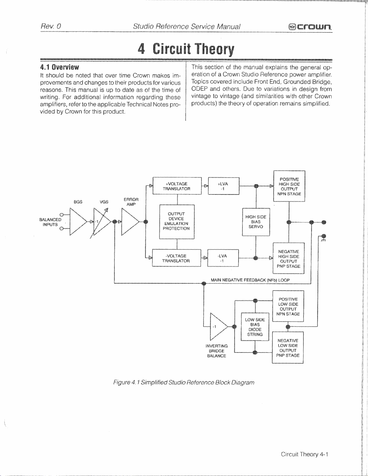
The
front end
Gain Stage
is
comprised
(BGS),
the Error Amp. Figure
of the front
4-3,f
lnpk~t
1/4"
Cir~uit Theory
end and
Balanced
ts
the
amplifier
inputs
may
Gain
be isolated
4-2
of
three
Variable
42
shows
Gain
a
stages:
Stage
simplified
Balanced
{VGS),
diagram
voltage ampixfieation stages,
Stage
(80%)
is
balanced, The
from
shield
from
chassis ground
and
the
by
4.4
Voltage
The
Voltage
the Error
drive
Amp
vol"s~ge?s
translating the
kV@c
referenee,
fication
and
muse there
stage,
the
gain
Alnplifi~ation
Translator
into
for
signal
drive
is
a
after the translatar
stage
separates
balanced positive and negative
the Last bltage Amplifiers
from ground referenced
LVAS
provide the
the
High
Side
slight
lass
of
gain
the
output
(LVAS)~
n
rnak
voltage ampli-
output stages.
in
the
translator
is
a
factor
of
15V
Be-
25.2,
of
to
Page 19
ence.
Their
outputs
drive
their
respechive
tVA,
muting
as
dictated
as
dietated
transistors,
by
th@
by
thg
The
BDEP
fault
circuit,
QQEP
transistors
circuitry
or
shunt
steal
the
drive
audio
Circuit
Theory
4-3
Page 20
Figure
bridgs output topology.
of
stages per channel: one
High Side of
NPN
trolling
stages
distortion
efficiency.
4,5.%
Thhe
conventional
the input drive vsitage becomes more po%itive, the
HS
10ad,
tion
PNP
going,
and
The
device.
two parts
class
resistorx
Isw
predriver and driver
tion
devices
1QOmW
to
put
The
positive half, except that
difference
in
cutoM
because
WS
Vbe
under static conditions,
halves
With a full base-emitter on voltage
predrivers
in approximately
the positive half,
tor in the negative
4.3
is a simplified
three deep DarDington (composite) emitter-follsw~r
the
bridge (driving the
and
one
PMP
an
the ground reference for %Re rails).
are biased
in
High
Side
High
Side (HS)
NPN
conducts
Eventually
and
+Vcc
is
biased
"Be
HS
the
HS
output
of
Sgsgethar, the predriver
sf
AB,
They
bypassing
about
and
the
device provides
negative half
value
180mW,
limit driver
are biased class
blr~tpat
load. Together with predriver
is
sa
that
level
under static
PNP
bias
is
rsgulated
multipiier which maintair-rs approximately
of
the
and
ta operate
the signal zero-crossing region and
[NS)
af the bridge operates much like
bipolar push-pull output configuration,
and
the
is
acrsss the
off.
When
PNP
canducts to deliver -Vcc to the load
NPN
stage
the
+LVA
the three-deep Darlington and are
provide output drive
the
base
they
switch on
sf
that the
PNP
PNP
devices require greater drive current.
WS
output
drivers, tha balance of
.3V
and
half,
exampfe
It
consists of
NPN
and
of
four
one
the
Isad),
the
Low
Side
of the bridge (con-
class
AB+B
delivers positive voltage
NPN
devices reach
load,
At
this time the
the
drive
signal is negative
is
off.
drjvm the base
and
of
$8.~
driver farm
through
output devicas,
An
RLC
network between
provide
an
the
output
by
phase
current
B,
averall cFass
HS
bias
(no
Q18,
are
Just
to
is
almsst
the
devices are
resistor is
devices
signal)
the
The
positive
in
parallel
$a
below
eonduct
Bias
at
shift
safs Bevels. Output
s%sculotf.
high
and
driver? the out-
AB+B
identical
slightly
run
closer
conditions,
Seavs,
and
with
drop
voltage
drop across
about
Q
J
bn$
~~nd~clior~
.5V
the
acrsss
bias
The
{and
grounded
quadrants
PNP
an
the
and
apse
The
output
far ultra
full
low
high
to
the
conduc-
HS
pradriver
the
first
biased
the
bias
Bevels
be-
the
As
csmpensa-
At about
current
output,
to
the
PNP
One
greater
to
the
This
QlS
is
3,2V
Vee
negative
this
3.2V
across
rasuits
resistors in
bias resis-
thus bias)
A
diode suing pr~vents
within the
Flyback
loads
from
minating circuit blocks
ing
the
4,5,2
The
supply
the
a
secondary
tha
ground,
other,
and
total difference
with
back
ence
ranged
AB+B
When
is
fed to an
inverted signal is delivered direeIIy to
positive
negative drive forces the
off),
Darlington drops.
ground, -Vcc
the pswer supply
tatai
forced
until,
and
a
positive pslarily'
%he
power
rail
is
a
(k72VDC
therefore,
sf
+"I
Cosrversely, during a negative swing
where
output
canduct.
ground
groidnd
SVCC
potential with
high
conduction output devices
diodes
to
dangerous reverse voltage levels. An output
amplifier
L@w
tow Side
bridge
high
but
This
-Vcc
respect
from
for
in
in
the
the
(NPN)
As
the
vsltage from
higher
at
the
+VGC
44v*
HS
a
positive
potential
patentraf.
=z
OV
shunt
bask-EMF
the
power supply to protect output devices
WF
through its output connectors,
Side
(L8)
(LS)
operates
rectifier
of
vsltage power supply
~Vcc remain canstant with respect
allows
from
the
io
ts
the HS
the
rails
a
three-deep Darlington
same
amplifisr output swings positive,
sp-amp
and
PNP
is
pulled toward ground reference.
above
positive
eq~aIs the total
supply
me?asur@d
the
amplifier output can reach a positiva
PNP
devices conduct,
This
would
and
a
negative pofariWy. Using
is not ground referenced, nor
the main transformer,
the pswer
same
potential, regardless
ground.
output
(AVCC),
manner as
stage
negative
devices
With
is
not ground referenced (and the
aVcc
ground potential.
amplifier output peak,
In
the
produces
voltage forcing
result
and
-Vcc
At
tl-$6
negative
-Vcc
equals
excessive
on
quite
bridge
The LS
$0
control
Both
where
(PNP)
LS
coaduct, VCB
LS
dsviics emitters tied
to
-Vcc
power
Reference
a
totat
from
ground
in
swinging
the tstal power supply
charge
pulses
output
differently.
floats
supply
rectifier
uses
LS
thc
PMP
is
supply potential with
hS
+Vcc
amplifier sutpvt
from
lines
in
othsr
with respect
to deliver
and
of
their voltages
inverted feed-
the
ground refer*
quadrants are ar-
and
WS,
it
is
inverted,
the
bases
LS
predrrivers.
devices on
constant)
This
1,
for
af14488
with
af
the
the
op-amp
NPN
swinging
further from
the
build
whew
reactive
from
enter-
The
power
wards,
to
each
+Vcc
fiitsr
as
are
biased
the
audio
This
of
the
The
(NPN
af
the
PNP
Since
+VGC
continues
-Vcc
-.
example,
from rail ts
ns
signal),
peak
HS
output
would
devices
tsward
peak,
same
ex-
up
off,
ter-
is
ta
a
to
is
OV
to
Circuit
Theory
4-4
Page 21
Rev
-..,-
0
E
!
t
k
I
rn
Sfudio
,,.
,
Reference
Service
Manual
@CraUme
k72VDC
statically)
is
capable
of
produsing
288V
rent (negative
An
iocrease
measurable
by
amplifi~r
in
positive
normal
output)
output
means)
and
signal
and
+Vcc
the
are
into
time
sensed,
a
load
delay
will
from
Page 22
@crown*
4.7
C@~tr@l
The
Reference amplifiers
to
guard
off
transients,
dew
comparator
tors
the
regulates
4.7,1
DCBF
The
amplifier output sigf-ral
pass filter
dew
comparator
eireuitry
against dangerous
At
the
~102,
thermal conditions,
the
fan
Pr@t@@
(R184,
--
-..-.-.
have
heart
?kg
speed
C
(UJQ21,
accordingly,
1
19,
R186
DC
sf
via
is
if
Studio
Refer~nce
-"-
fault protect circuitry
voltages
this
~ir~~ifry
fan
control girc~ij:
the
passed
*and
DC
and
OBEP
eireuit,
through
C107)
ts
campsnent exceeds a predetermined level, the output of the
parator (pins
pin
23
going
transistors
opening
4,7,2
Fsuft
The
fau&
disa$le the
put
fault.
output
tive
The
Q329
are
(pin
supply
The
a126,
and
semicsnductars,
sections, draw excessive currents,
[ow
and
conducting excessive
13)
and
high
Qf
BNP drive
sentation
wnt
occurs,
through the
4.1.3
TBFR
During
which
causes %he
to
be
!OW
13
high,
lay
K2,
and
tors.
Aft~r
charged
13
to
go
1
and
2)
goes
to a high
and
the
relay
Circuit
circuitry
high
A
fau/$
state
disables
K2.
is
designed
energy
is
defined
supply
in
side
of
Q130,
is
forcegs$
mutes
side
27
and
of
output
&ridge
to the
fault detection consists
ff
both
NPN
high,
This
the
audio
sf
bridge
U101.
This
feedback
devics
the window cegmparatsr
opto isslatsr
8n
Bs%ay
power
up,
the
capacitor
U101.
nan-inverting
and
the output
the
high
energy
the
audio
approximately
and
pin
10
low
and
the
(pin
taik
is
mutsd
is
pulled
amplifier
law.
The
result
which
turns
on
the
high
energy
to
mute
in
the event of
as
any time
both
the
and
cajirrents,
disables
PNP
in
negative
output devices
tha
output
the
high
path,
fault
detection
consists
circuit compares the
signal,
current.
input
13)
are
by
4
seconds,
high,
to
giving
If
excessive
U
1
Q2
is
C'I
18
is charging,
{pin
-4
$0
be
high,
disabled by
the muting transis-
C1
thus
causing
:,cams
out of
the
supply
audio
which
and
sf
triggered
09
With
"I
standby-
turn
on/
the
win-
moni-
and
a
low
the
win-
cam-
is
U302
muting
by
and
an
out-
the
posi-
Q128,
af
U'T82
energy
of
NPN
a
repre-
cur-
of U 182
pin
the
re-
Qis
fully
pin
Service
nal.
ManuaE
p..-.p
As
the outpeat transistorlheatsink
Peratu~e, the
+joVBC
both
QDEP
nal to change,
-12.5VDC,
up
at
+
1
2,5VDC0
input
of
the
high
$+24V),
more
positive,
the
ing
U4,
AG
Ph@
$he
QP-amP
U7
A,
madule.,
from the
tars
detector.
is
turned
ing
type
waveform
the
fan
fan.
Therefare, the
'The
u!@
and
fief
is
fan
an
opts-triac,
supply for
Gating
Q3,
and
C12
+15V
the
tine
Every
sa?
waveform.
is
contrkal
f%f?
Enabje
holds the
in
standby<
the amplifier
At
the
heart
of
power
energy,
and
plies,
the
ings in
4,8,1
824
such
pawere
may
shift
transformer,
secondary
there
is
"f?er@
transfarmer
the
event
AC
tin@
and
025
that they
This
develop
in
the
AC
---
increases
ODEP
f3ear
vsltages
The
3rd
op-amp
and
this output
accordin~j~~ The output of
Signadis
Uj@+
the
and
supply,
voltage
lime the
and
used
signat
is
in
the
one
is
also
wtlich
Filter
are
null
done
a
mechanical
waveform
voltage
~~~Cv
it
will
fan
contra& signal starts
after
complete
Phis
voltage
U
1
B,
as
the
fan
which
fhe
fan,
fed
into
This
gating signal
Fan
Enable
RE3
farm
begins
wave
line
discharges
The
higher
to
turn
off
itself
fan cantrod curr~nt
%nai
cQm@s
Gating
"I^'herefsfe
standby*
power
low voltaga winding
Si~flaf
supply
There
windings,
a
thermal
will
disable the
kvei
will
If 1s
Cause
the
ODEP
is fed
a
drop
fan
limiting,
into
The initial output
will
in
farm
turn
an
control
became
the
signal
signal
low,
drives
nsn-inverting
is
from
RC
timing circuit that,
Is
charge,
and
is
a
waveform crosses
C12,
This
causes
p~$i$ive
%he
~pto-triac,
is
aF
a value
portion
ks
has
from
the
display
high
when
the
fan
will
not
is
a
muiti-tap torraidaH
are
two ungrounded, high
one
for
each channel,
for
eu%
off
switch
secondary
of the transformer overheating.
ir-t
the
AC
out
any
because
primary,
DC
the tarriodiat
buzz
applied
They
compo9-ren"in
if
them
to
the
R@K
in
tem-
drop fmm
in
one of
csntroi
out
the inverting
U1
Q4,
a
p~~duct
the
U1A
Oil
aven
turn
a
duty
the
turn
the
transformer
is
transfarmer
sig-
around
ends
sf
U1
B
becomes
thus
turn-
I3
drives
a
triac
input
display
rnoni-
crossing
OV,
a
ramp-
of
.&he
when
sn
the
cycle,
!"nod-
amp&
when
24V
sup-
built into
wind-
are
wired
the
AC
any
DC
of
of
Q4
Q
, , ,-
is
in
4,7,4
Fsn
The
F8n
bias
valfages.
voltages
Circuit
Theov
Centre!
ContrdSi~na$is
Both
are
eambined
4-6
t.aken
channel
to
from
1
and
create
the
channel
the
positive
fan
c~rrtrsl
ODE$
2
ODEP
sig-
inrush current that
rmer, a SO%$
Start
is
possible
Circuit
has
with
been
the
in-
Page 23
and
power
4,8.3
Over
Ul
El
serves
of
over line
vslfags
high
energy
plies
the
as
the
window
of
U1
D,
applied
tisn
and
to
remain
Resistors
ping
neWsrk
ground,
supply
R4
Hevel
will
is
applied
exceeds
switches
placing
biases
4.9
4.9.1
U3A
R15
has
-7V
a1
the
and
biased
pacitor
the
off
Display
ilOC
and
and
a
window
U3A
and
error
switches
on
C27
human
is
applied
Voltage
as
a
voltage
sxceeds
power
regulated
reference
&he
output:
across
allows
Q1
ensrgired
W3,
W4,
from
As
the
line
increase,
to
%he
states,
a
logic
Q
1
and
Circuitry
U3B
serve
R'W
7s
level
and
U38
the
10~
amp
appears,
the
and
the
makes
eye
to
diractty
Proteetion
window
cantro!, In the
10%
over
supplies
+
I
SV
(pin
033
and
to
remain
R5
and
the
unregulated
voltage
The
Pin
1
1
(non-inverting
window
This
allows
high
on
the
de-energizes
as a
voltage comparator
the
r@sistor
of
+7V
have
LEO
El,
the
state
of
tOC
LED,
sure
the
see
it.
to
the
comparator
the
rated
are
to
pin
"I
level.
With
13)
has
a
014,
This
on,
which
R6
serve
incraas~s,
voltage
level
Dl
3
base
iievsD
of
and
0%
K2.
dropping
and
pin
a
logic
high
when
ths
7V
window
U3A
and
El,
iliuminates.
LED
is
transformer.
for
the
event that
line
voltage,
disabled,
of
U
1
B
and
pin
10
in
logic
law
prevents
thus
allows
a$
a
resistor
+24V
supply
the
unregulated
sn
the
input).
When
pin
-10,
the
0
14
to
canduet,
01%
This,
with
newark.
4
has a window
which
Signal
is
overcame
U3B.
Q1
lit
long enough
purpose
the
line
the
W7
%up-
serves
csntrof
which
csndue-
K2
drop-
to
wiper
of
the
circuit
iu
turn,
R13,
Pin
of
turns
off
fro.cam
is
then
The
ca-
for
4,9.3
Signal
incorporated
is
ef signal
SB
U
1 A and
nal.
E3,
at
(Signal
U1
which
the
autpkdt of
indication.
B
takes
Dynamic
With
the
switch
fied
audio
sequence
fied
but
unfiltered,
of
%he
audio
serve
as
Range
vide
puts
This
ing
amp,
the
the
pull
ranga
'7'
Output
With
signal
paratsr
non-inverting inputs,
$rated
display
plifier"
LEDs.
a resistor
"l
athe
same
i~lputs
U1
C.
nan-inverting
inverting
of
each
of
tha
Leved
the
switch,
is
still
drivers.
reference
balance between
Indlcatlan
on
the
Presence
D3
serve
this
illuminates
the
Range
51
signal
is
of
window
waveform,
the
current
R29,
dropping
LED
drivers,
reclifisd
via
the
This
filtered
inputs
inputs
LED
signal,
$1,
placed
A
small
far
display
to
module are three
Bndicnfiow)
rectify the
rectified signal
any
timg
amplifier
in
the
placed
comparators.
therefore
channel,
Dynamic
on
the
it
contains
U3C,
U3D,
sources
R3t
R33,
W35,
network
signal
is
placed
filtering
Function
sigr~al
is
receiving
receiving
th~
comparator
in
the
Level
on
the
inverting
DC
level
This DC
comparatofs.
the
two
amplifier
and
there
position,
invsrtin~
This
USA,
for
the
R37
for
an
of
of
an
the
peak
equals
positian,
inputs
is
piaced
level
serves
W78
channels
output
drives
is
signal
inputs
signal
ah@
peak
U5B
five
and
the
inverting
the
non-invert-
C3
and
RMS
value,
RMS
value, and
value,
the
the
af
ow
as a cali-
calibrates
sf
modes
sig-
the
LED,
pre~ent
this
recti-
of
is
recti-
value
and
U5B
Dynamic
R39
pro-
in-
the
op-
With
the
aut-
dynamic
peak
the
corn-
all
of
the
the
the
am-
a
4,9,2
U1
B
the
OBEP
tions
BY
ts
signal
60EP
on
the
pin
14
conduct
drops
display
LED
of
Uf
and
ts
E15,
D
the
module
Under
is
a
negative
El5
point
is
the
normas
to
illuw~inate.
wkiiere
OBfP
curr@nt
operating
vsitags.
As
limiting
source
condi-
This
allows
the
ODEP
far
takes
Circuit
Theory
4-7
Page 24

@crmwmx
-""...."-
St~~dia
-,.-
Reference
Servjce
" ""
Manuaf
-...--
This
page
intentianally
left
blank
Circuit
Theory
4-8
Page 25
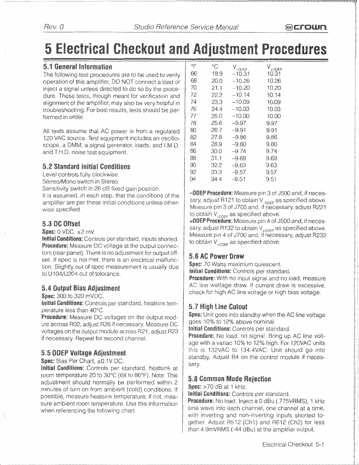
R@K
----...,
0
-...I.....YIIIIIIIIIIllllYllllllYl
...-
-
,,, ,, ,
Studio
Reference
Service
, , ,,
Manual
-.,-
mcrmwn*
5,2
Standard
Level
controls
StereoBMano
Sensitivity
It
is
assumed,
amplifier
wise
specified,
5,3
QC
Offset
Spgc;
8 WBC,
lnltial
Ce~dttOax~gr
Preeadurs:
tors
(rear
set.
If
spec
tian,
Sligh8fy
to
U"iQiU204
5.4
Output
Spec:
300
ilnitiall
Gandstiaa$::
peratare
P~oeedurs:
ule
across R02,
voltages
if
necessary.
5.5
ODEP
Spat:
Bias
InltiaiP
@oiaridition%:
room
temperature
adjustrnerr"rh8ufd
r~rintsts%
possible,
sure
when referencing
07
ambient
initial
fully
switch
switch
in
are
per
k2
Msasure
panel).
is
not
out
0165:
Bias
ta
320
less
than
Measwe
adjust
on
the
output
Repeat
Voltage
Per
Chart,
turn
an
measure
room
Checkou
Cowdltigns
clockwise.
in
Stereo.
in
26
dB
fixed
each
step,
that
these
initial
rnV
Controls
There
met,
of
of
Adjustment
rnVDC,
Contrais
ContnaSs
the
per
DC
voltage
is
ns
adjustment
there
spec
measurEment
tolerance,
per
40°C
DC
voltages
R26
if
module
for
second
Adjustment
~6,4V
DC.
per
20
to
30°C
nsrmaliy
from
ambient
healsink
temperature.
temperature;
$.a/lawing
gain
pasition.
Ehe
conditions
conditions
standard,
is
an
standard,
B-eecessary,
across
at
the
afectricai
or?
the
R21,
mputs
sutput
channel.
standard,
(68
to
86°F)"
be
performed
(esfd)
Use
this
chart,
of
the
unless
other-
shorted
canncc-
for
output
off-
rnaifunc-
is
usually
healsink
output
Measure
adjerst
due
tern-
mod-
DC
R23
heatsink
Note:
This
wilhin
cornditions,
if
not,
msa-
infarmation
at
2
If
t8,9
28.0
21.7
22.2
23.3
25.0
25,6
26.7
2723
28,9
30.0
31.1
32.2
-ODEP
to
+OOEP
sary,
Measure
5,6
Spbc::
initial
Proe8Bure:
sary,
adjust
Measure
obtain
~rocgiite:
adjust
oblasn
BC
Power
70
Wazrs
Csnditions:
pin
V
pin
v+OL)EP
Procedure:
AC
line
wattage
check.
far
high
5.7
High
Spec:
Unit
goes
^f
8%
lnltial
Gondltionsl:
Proeedgre:
age
with a variac
this
is
132VAC
standby.
Adjust
sary.
5.8
Common
Spac:
>70
initial
Cendilions:
Prosgdure:
sine
wav@
wieh
inverting
getkaer.
than
Adjust
4,9mVRMS
-10.31
--10"26
.-.18.28
--16.14
.-"i.09
--toO~W
--9.97
--8,9l
-.9+86
-9.80
-9.94
-9.69
-9.63
R121
3
of
,,,,
as
R132
4 of
as
Draw
nmaximkam
With
no
AC
Line
Gutout
goes
into
to
to
12%
Controls
No
load,
is
R4
Mode
dB
at
1
Controls
No
load,
into
each
and
R512
(-44
Measure
to
J700
obtain
and,
pin
V
s~ecifred
~easure
to
J700
Controls
input
draw.
Iim
standby
aabw
obtain
and,
si~nal
if
voltage
onominal,
pin
V+,,,,
quiescent.
per
current
par
no
signal,
10%
to
12%
334.4VAC.
sn
the
control
Reje~tion
kHz,
per
Inject
a
0
channel,
non-inverting
(Chl)
and
dBu)
at
Procedures
1039
10+26
18.20
1Qs?4
1Q,$39
1O.W
9.97
9.91
9.86
9.80
9.44
9-69
9.63
3
of
3500
and,
if
news-
,,,,
as
specified
if
necagsarx
above,
4
of
3500
as
specified
if
necessary,
standard.
and
BBQ
16ad,
draw
or
high
bias
when
the
AC
standard.
Bring
up
high.
Far
120VAC
Unit
should
module
standard,
dBil(.775VRMS),
one
channel
inputs
RE12
(Ch2)
the
amplifier
above.
adjust
and,
if
neces-
above.
adjust
measure
is
excessive,
vsitaga.
line
voftage
AC
line
go
if
neees-
1
at
a
shorted
for
output.
R22t
R232
volt-
units
into
kHz
time,
to-
less
Elcctrfcal
Checkout
5-1
Page 26
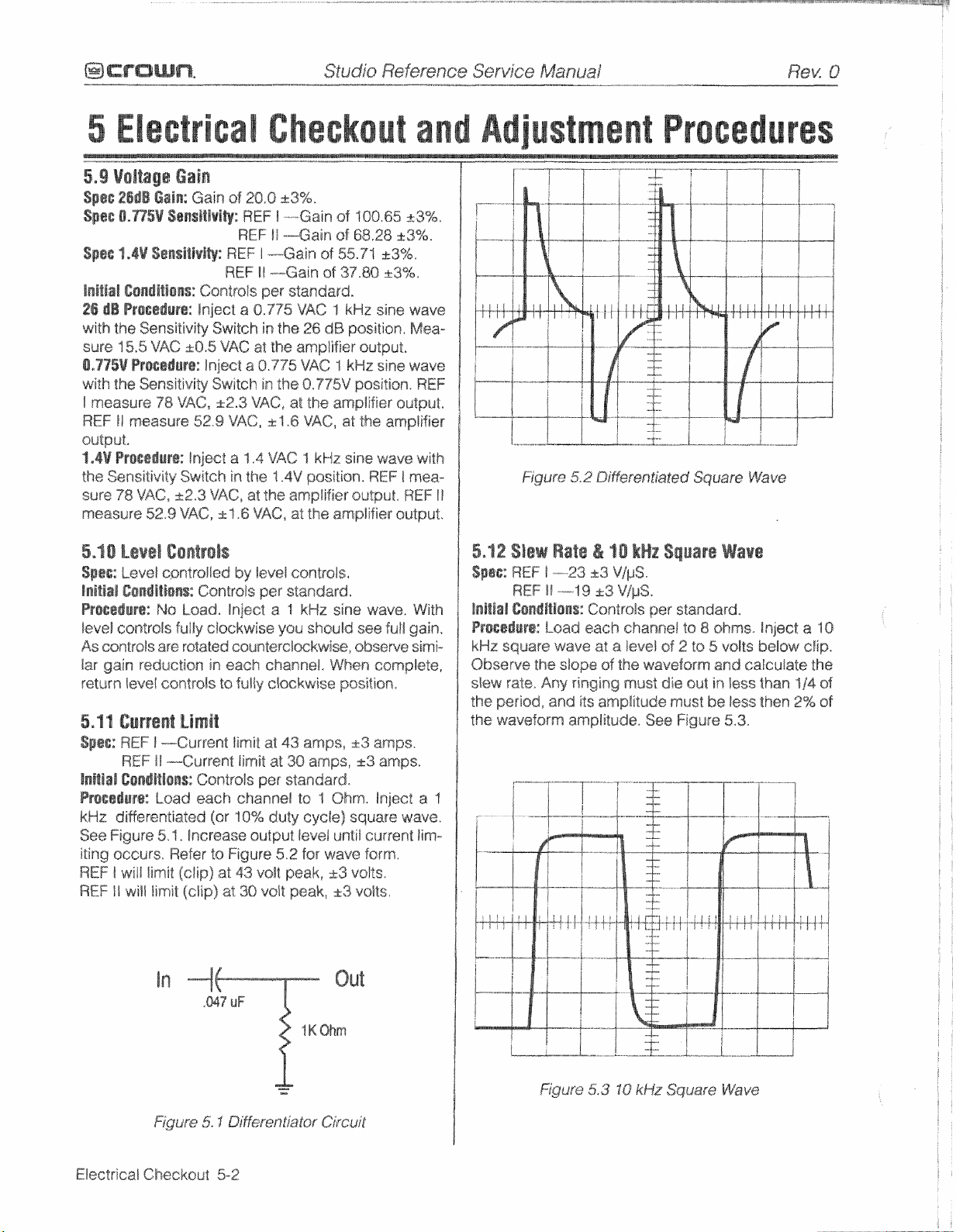
5.9
Voltage
Spee
2666
Gg%n;
Spac
0.775V
Spec
1.4V
Inibtia%l
26
dB
with
the Sensitivity
sure
15.5
0,775V
with
the
i
measure
REF
II
output.
1
.@V
Bros@dure:
the
S~n~itisgify
sum
778
measure
5,10
S@@s:
Inltlairl
Bre@adur@:
level
controls
As
controts
Iiar
gain
return
5,lf
Current
Spec:
lnrtlal
Procad&~s:
kHz
differentiated
See
Figure
iting
occurs,
REF
f
REF
II
5e~%itlvi~:
S~nsltivlQ:
Eondlti@n%:
Procsduf@:
VAC
Prosedut~::
Sensitivity
78
measure
VAC,
52.9
Level
C~ntrsls
kevef
cantroiled
Conditiows:
No
are
reduetisn
!eve8
contrsls
REF
1
---Current
REF
II
-Current
Csndftians:
Load
5%
f
Refer
will
limit
will
limit
Gain
Gain
of
REF
REF
Controls
Inject
Switch
f0.S
VAC
Inject
Switch
VAC,
f2.3
52.9
VAC,
lnject
a
Switch
&2,3
VACF A 1.6
in
VAC,
Controls
Laad,
lnject
fully
clockwise
rotated
eountercixkwise,
in
each
$0
Limit
ConWols
each
&ear
.
Insrease
$0
Figure
(clip)
at
(clip)
at
Gheckou
20,8
k3%.
REF
I
."---Gain
REF
!i
-~~~~~~~~~Eain
I
---Gain
t
l
----Gain
per standard.
a
0,775
in
ths
at
the
a
0.775
in
the
VAC,
;s;.
"1.6
1,4
VAC
the
1.4V
st
the
amplifier
VAC,
by
level
per
standard.
a
%
you
channel,
fully
clockwise
fimit
at
43
limit
at
30
per
standard.
channel
38%
duty
output
52
43
vstt
peak,
38
v~iwpeak,
at
af
of
5521
st
37
VAC
1
kHz
26
dB
position,
amplifier
VAC 1 kHz
8.975V
at
Zh@
amplifies output.
VACt
at
1
kHz
sine
position.
at
the amplifier
controls,
kHz
sine
should
&$hen
pssitian,
amps,
amps,
ta
7
Ohm.
cycte)
square
level
until
for
wave
2~3
k3
'508.65
68,28
~3%.
&3%.
.SO
a3%,
sine
skstpu2.
sins
position*
the
amplifier
wave
REF
output.
output*
wave.
see
futf
sbsewe
complete,
323
amps.
k3
amps,
Inject
current
Form.
voltss.
volts,
&3%,
wave
Mea-
wave
REF
with
1
mea-
REF
With
gain,
sirni-
at
"I
wave.
lim-
I!
5.12
Spac:
lnltrai
F~ecedurg:
kHz
Observe
sllew
the
%be
Figufe
Slsw
REF
REF
5.2
Rate
1
-23
If
-1
eondltlo~s:
Laad
square
wave
the slope
rate,
Any
period,
waveform
and
amplitude.
DiF@r@nZia$ed
&
10
kHz
d3
V/pS.
9
~3
V&S.
Cantrsls
each
~hawwel
at
a
level
af
the
ringing
must
its
amplitude
Procedures
Square
Square
per
standard,
to
8
of
2
ts
waveform
die
out
must
See
Figure
Wave
sk~rns.
5
volts
and
in
lass
be
less
5.3.
Wave
inject
below
catculate
than
"44
then
2%
a
10
clip.
the
of
aOf
Electrical
In
-I
Checkout
5-2
Out
Figure
5.3
IQ
kHz
Square
kVave
Page 27
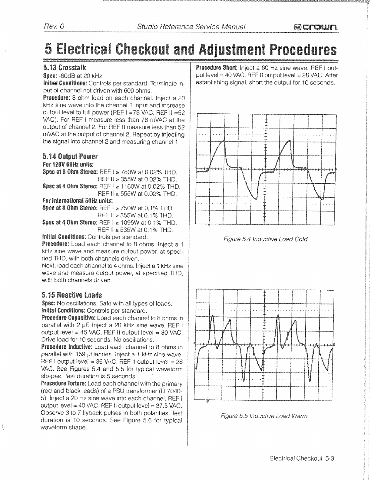
Checkau
Procedures
5.13
Crosstalk
s~@@:
-6048
Injt[g[
put
of
P~@~@@uP@:
kHz
sine
sutput
VAC)*
output
mVAG
the
signal
5.14
Output
For
12@V
Spec
sf
Spas
st
Far
lntsrnatignal50Hz
%pee
gt
spec
af
Inlt%al
C@@difi@~$::
Proced~re:
kHz
sins
fied
TWD,
Next,
load
wavg
and
with
both
at
20
kHz,
C@nd[tisns:
channal
wave
level
For
of
channel
at
the
not
8
ohm
into
to
full
REF
l
output
into
channel
Controls
driven
load
the
pawer
measure
2,
Power
@@Hz
enftg:
8
OAm
Stereo:
4
Ohm S~~PBQ:
8
Ohm
%tare@:
4
Ohm
B8t@reo:
Controls
Load
each
wave
and
with
both
channels driven.
each
channel
measure
channefs
driven.
per
with
on
each channel,
ehannei
(REF
less
For
REF
of
channel
2
and
REF
I
REF
fl
REF
I
REF
if
unl%:
REF
Ii
REF
If
REF
i
REF
::
11 2 535W
per
channel
measure
to
4
output
standard.
800
ohms,
1
input
f
=78
than
is
measure
2.
Repeat
measuring
z
780W
2
355W
r
1
'I
60W
a
555W
a
7750W
a
355W
2
1095W
standard.
tea
8
output
ohms,
pawer*
at
T~rmi~ai;e
Inject
and
VAC,
REF
78
mVAC
less
by
channel
a"lQ.62%
at
8,82%
at
O-02%
at
0,02%
at
O,S
%
at
0.1
9&
at
8.1
%
at
0.1 % THD,
ahrns.
power?
Inject
a
specified
inereass
11
at
than
injecting
THO,
THB.
THD.
THD,
THD,
TWD,
IHD.
lnject
at
speei-
3
kHz
THD,
in-
a
20
=52
the
52
1.
a
sine
1
Prccedure
put
level
Shed:
=
46
Figure
inject
VAC.
5.4
a
6Q
REF
I!
Inductive
Hz
output
sine
fewel=
Load
wave.
28
Cojd
REF
VAC.
I
out-
After
5,15
RsaeSIve
Spge:
No
oscillations.
llnltlal
C@nd%Olons:
Procadurn
parallel
output
Drive
Proeed~r~
parallel
REF
VAC,
shapes,
ProseBure
(red
51,
output
Observe 3 to
duration
waveform
ievei
load
I
output
See
and
inject
level
with
Capaeitiue:
with
2
=
for
Onductiv~:
159
level
Figures
Test
duration
To@uf@:
black
a
20
=
40
7
is
10
shape,
Loads
Controls
Load
yE
Inject
45
VAC,
1
0
seconds>
Load
yHenriss.
=
36
5,4
Load
Beads)
Hz
sine wave
VAC*
flyback
seconds,
Safe
per
a
REF
each
VAC*
and
is
5
each
sf
a
REF
pulses
See
with
ail
types
standard.
each
channel to
29
kHz
II
sutput
No
oseiliations.
channel
Inject
a
REF
fI
5.5
for
sscsnds.
channel
PSU
transformer
into
each
11
output
in
both
Figure
of
sina
wave,
level
1s
1
kHz
satput
typical
with
Zhs
channe!,
Ievd
--
polarities,
5,6
Soads.
8
ohms
REF
--
30
VAC.
8
ohms
sine
wave,
Ieval
=
wavsform
primary
$D
7040-
REF
375
VAC.
Test
far
typical
in
in
28
I
I
I
Electrical
Checkout
5-3
Page 28
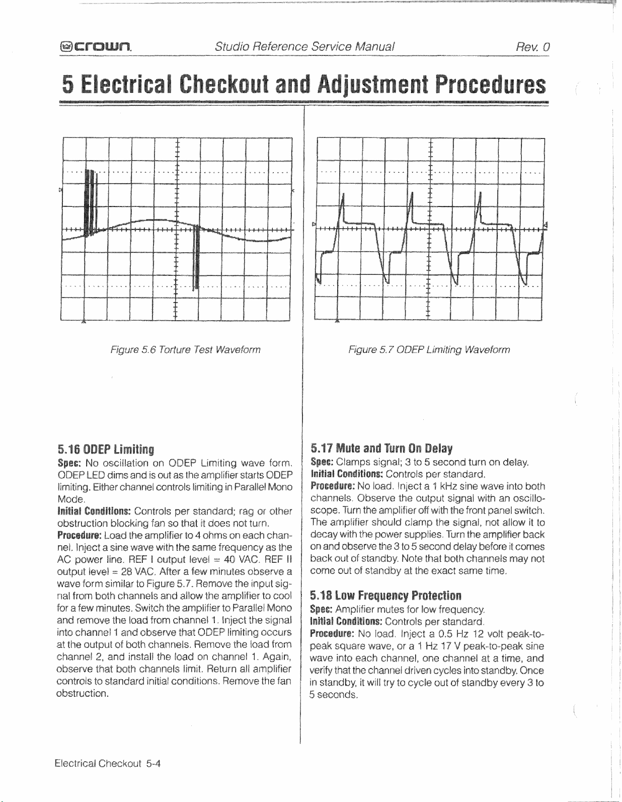
Checkou
Procedures
5,16
ODEP
Spss:
QDEP
fimiting.
No
ascillatisn
LED
dims
Either
Limiting
Mode.
initsat
Con@itlong:
obstruction
Ftacedufe::
net,
Inject
AC
power
&a~fpkifleve1
wave
nal
from
for
a
few
and
remove
Ento
channel
at
the
channel
observe
controls
a
form
both
minutes.
output
2,
that
$0
blocking
Load
sine
line.
=
similar
the
1
BE
and
bath
standard
obstruction.
on
and
Is
channel
Centrals
fan
the
amplifier
wave
REF
i
28
VA6,
to
Figure
channels
Switch
load
from
and
obsarve
both
channels.
instail
channels
initiaf conditions.
ODEP
out
as
esntrols
per
so
that
with
the
output
After
5'9.
and
ailgaw
the
amplifier
channel
that
the
load
Limiting
the
amplifier
limiting
standard;
it
does
to
4
ohms
same
level
a
few
minutes
Remove
the
1.
QDEP
Remove
an
lirnik
Return
wave
starts
in
Paratief
rag
not
turn.
ou
each
frequency
.--
40
VAC.
observe
the
amplifier
ta
Paraltsi
inject
the
limiting
the
channef
all
Remove
form\
QDEP
Moue
or
other
chan-
as
the
REF
input
sig-
to
cogs!
Mono
si~nal
occurs
load
from
3.
Again,
amplifier
the
fan
5.17
Mute
Sp@@:
Clamps
initisi
Coadition%:
PP@@@$u~@:
channels.
I!
a
scope.
The
decay
an
back
come
5.1
$@I@:
InibIail
Turn
amplifier
with
and
observe
out
out
8
Low
Ampiifier
C~nditions:
Frocgdure:
peak
square
wave
into
ygpify
tnat
in
standbys
5
seconds.
and
Turn
signal;
NO
load.
Observe
the
should
the
of
standby"
of
standby
Controls
inject
the
amplifier
pswer
the
3
to
Note
3
clamp
supplies.
at
Frequency
gwutas
for
C~ntrols
No
/sad.
Inject
wave,
each
channel,
$he
channel
it
will
lay
to cycle
driven
On
Delal
ts
5
second
per
staradard,
a
1
kHz
sine
output
5
the
off
with
the
second
thal
exact
signal
the
signal,
Turn
deiay
both
same
Proteclion
low
frequency,
per
standard,
a
0.5
HZ
a
2
Hz
"I
one
channel
cycles
out
of
standby
turn
on
delay,
wave
into
with
an
assillpa-
front
panel
switch.
not
allow
the
amplifier
before
it
comes
channels
may
time.
12
voft
peak-to-
ppgak-to-peak
ak: a
time,
into
standby*
every
both
it
to
back
not
sine
and
once
3
to
Electrical
Cheekoast
5-4
Page 29
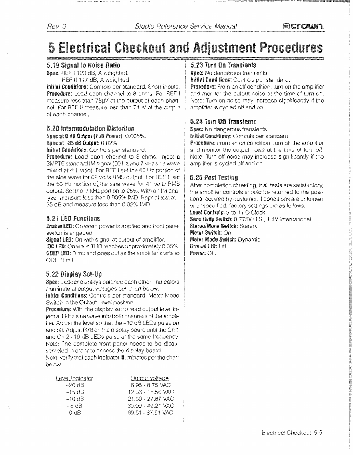
R~K
Q
-
-.-.
"..........
<..."<.
Studio
R@f@f@n@e
--"<,."....---
Service
Msnuaf
, ,
-
@crownq
I
i
f
5.19
Signal
Sgse:
REF
REF
of
each
5.20
!ntarmeduiali@n
Spec
at
8p@s
at
Inltia1
Cowdltlons;:
35
dB
and
to
I
120
11
117
channel.
O
dB
Oatp~t
-35
db Output::
measurE
Ncise
dB,
A
weighlsd,
dB,
A
(Fgil
0.02%+
Controls
less
Checkou
Ratio
wwsighbed,
ai%t@@$a@
Powsr]:
per
standard,
than
0.02%
8.005%.
IMD,
5.24
Turn
OH
Trsnsients
spas:
Na
dangsr~us
laitis!
GonditisnsX~ontrsls
Pro~8lure: From
and monitor
the
transients.
per
an
on
condition,
output noise
Procedures
standard.
turn
sff
the
amplifier
at
the
time
of
turn
08.
5,21
hEB
switch
ODEP
5.22
Sp@g;
is
engaged,
limit,
Display
Ladder
oilurninate
initial
Gssditlo~s:
Switch
in
the
Prosedurs:
ject
a
1
kHz
fier-
Adjust
and
OM.
Adjust
and
Ch
2
-10
Note:
"I"@
sembled
Next,
below.
in
verify
Funstions
Set-Up
displays
at
output
With
sins
the
complete
order
thaheah
voltages
ConlroBs
Bu%put
the
display set
wave
level
se
R78
sn
dB
LEDs
to
access the
Leve!
front
indicator
balance
per
pea
positioa.
into
both
that
the
"Ihe
display
pulse
panel
each
other;
chart
below,
standard.
to
read
output
channels
-18
dB
LEDs
board
at
the
same
needs
display
illuminates
OadicaWors
Meter
Bevel
of
the
ampli-
puke
until
the
fraquency*
to
be
disas-
board.
per the
Mode
in-
an
Ch
1
chart
Eiiestrical
Checkout
5-5
Page 30

This
page
intantiarmally
ieft
blank
Electrical
Checkout
5-6
Page 31

6
Schema
Schematics
6-
1
Page 32

Phis
page
intentionally
left
bblank
Schematics
6-2
Page 33

Rex
0
--...-.."."---"",,~.".-
7,1
General
This
chapter
the
Studio
chapter
cluded
tains
7.2
Many smaller
ths
Studio
avaiiabfe
some
actually
sur~
as
covers
7.3
When
model
and
Price
7.4
Shipment
method
made
counts
paid
on
a
basis,
Reference
are for
on
a
artwork
Standard
Wefersnce
from,
electronic
speerial,
aa~r
acceptabje
and
Ordering
ordering
and
Crown
Shipment
Part
quotes
wfif
unless you
$0
and
with
and
will
C,O,D.
Ilnfo~matian
confairas
all
module
and
md
electrical
panels
il[usiratisns
ampfifi*ers.
mechanical
(circuit
parts
lists
Spe~ial
and
amplifiers
electranie
parts
that
A
part
ordared
replacement.
are
Pads
parts,
be
serial
number
Number
are
available
be
normally
speciQ
from
Elkhart,
Crown
will
be
billed,
sr
pre-payment
receive
A11
The
parts
board).
For
alf
Parls
elsctronic
are
supply
appear
from
Structural
available
sure
to
at-ed
include
(CPN)
from
on
request.
mad^
by
%,thewise.
IN,
only.
shipment freight
others
will
(check
Studgo
,
..,,,
..,
, ,,, . ,
Referenee
Sgrvice
77.5
and
parts
lists
for
Normal
parts
lists
in
and
parts
Chapter
modules.
parts
stacked
houses,
to
be
standard
Crown
items
only
from
give
the
a
description
the
parts
UPS
or
best
%hipm.wenls
Established
re~eive
or
credit card)
this
not
8
COD-
used
by,
and
However,
are
will
as-
such
Crown.
amplifier
listing.
other
are
ac-
pre-
shipment
iw-
in
I
those
Crown.
weighed
which
made
turned
authorization
be
obtained
The
warehause.
ing
Grown
Part
our
notice.
7,6
Contained
lists
electrical
ings
quantities
shswn
idoatified
Manual
Terms
terms
are
firms
having
If
pre-paying,
before
an
amount
upon
r@ceipl
$or
credit
from
before
Crown
Parts
Parts
products,
prjces
and
avai!abi/ity
Illggtrated
within
far
the Studio
and
elec"lrsnic
are
referred
used
in
the
circuit
there
by
pre-paid,
a
total
due
are
the
returning
Net-30
pre-established
the
order
bill
can
will
be
a$
pre-payment,
subject
fs
Crown
parts
Department
sold
by
Crown
are
Pa@$
Lists
this
section
Reference
to
by
Crown
are indicated.
schematics
circuit
are
parts
Part
designation.
@CrOUme
days
applies
a~caknnts
must
be
be
estabJisked,
issued
a
Parts
is
SU~~@C$
B
and
in
Thosa
{chapter
and
New
10%
re-stocking
Department
for
credit.
not
a
general
are
solely
to
chang~
the
illustrated
I&
amplifiers,
ths
assembly
Number
parts
to
packed
shipment
parts
parts
For servic-
parts
draw-
$@PN),
are
61,
and
0111y
with
and
after
re-
fee,
must
with-
The
and
also
are
Pa~s
MailingAddress:
PO
Efkha~?
$obi
IM
Plant
19%
W,
EQkhaa,
Phone:
Ere:
Crawn
Department
Bsx
1080
USA
46$"s5-100$$
2
SxWe
Mishawaka
%N
USA
(21
9)
294-8280
(Ma)
Rd,
48519
M24939
Parts
fnfarmation
7-1
Page 34

crownv
-
--.Y..._YY_IIIII-.P-
Studs
Refercs?r_;le
---
,".-"--
Service
Manual
-"
,,..,
",.."-
, ,
-
Parts
Information
7-2
Page 35

1
2
$crew,
8-32
End
x
.75
Cap
FLSHD
End
Cap
3
4
5
6
9
8
9
10
3
1
22
13
14
25
16
Screw,
Hoidea;
SCFGW,
DPDT
Screw,
Dtsplay
Display
Pot,
8-32
Main
Gablo
6-32
#8
Star
On/Off
6-32
SCWW,
Screw,
5K
ohm
t
solatsf?
Display
Handls
x
0.5
Chassis
Fishpaper
x
.3f
2
Washer
Push
Button
x
318
4.40
x
6-32
x
Module,
Module,
Linear
LED
Bracket
FLTHD
QNHB
Switch
PNHO
395
.3125
REF
REF
31
Det.
Foam
T1
5
TrI
I
II
Handlss
Display
Covers,
OnlBfF
Display
Brkf
etc.
Switch
Not
3
7
18
19
20
21
22
23
24
Shown
25
Front
Screw!
Front
Set
Screw,
Pane!,
Overlay,
Overlay?
Air
8-32
#8
Star
Panel,
Bottom
Finger
Knob
Screw,
8-32
x
Push
Top
Extrusion
REF
REF
Filter
x
-37
Washer
Gr~ard
6-32
.5
PNHD
Button
t
il
WDWB
Extr~aion
x
,I8
Taptits
Parts
Btm
Extrusion
Sub
Front
Level
Level
Knobs
Mandlas
On80ff
Information
7-3
Page 36

@crawm*
-.........-
Studio
.
Referer7ce
Service
1*1
.-.m1..-
Manual
P
RevK
0
Page 37

Parts
information
7-5
Page 38

@crown*
-p-"-.s"p.
Studio
Refergnee
, ,,
P-"
Service
Manual
--,..-P-
Parts
lnfsrmatiorl
7-6
Page 39

Studio
Reference
Service
Manua
f
--
Screw,
Spacefx
Board
Screw,
Clamp,
crew,
6-32
1
x
Back
Power
8-1
8
Main
375
Toggle
Support,
6-32 x -3
TO-22On8-3P
Output
x
.56
.625
Rubber
Pan&
W8sher8
Transfarme&
x
1.375
PNWD
Madufe
Nut
7$8
Lock
f
2
Par?
Assambly
Washer
Grommet
Assembly
112
Steel
REF
Plastic
Hd.
Head
1
8$1018%10822
T15
T?5
POW@%
$crew,
Tran~forrner,
f
12-20
x
4
Hex Cap
REF
I!
I
I
i
Parts
information
7-7
Page 40

@Crownx
-...-
Studio
,,, ,, , ,, ,,, ,,
Reference
--,-."
Service
Manua$
.,...p"
Rev+
pu..,"-
0
Page 41

Back
Bask
Panel
Pane
Plate
Shield,
Screw,
REF
REF
Dual
Wire,
Wire,
Wire?
Wire, R 12
Solder
Circuit
8-32
Screw,
WasherE
I
Circuit
I!
Circuit
Strain
Pip
Cage Assom
Binding
Jumper,
#I2
#I2
#12
Lug,
Breaker
x
38
6-32
x
W6
lnt,
Breaker$
Breaker)
Relief
Past,
2
Position
BLK
22
BkK
RED
RED
#8
PNHD
.25
Shar
bty
Gald
in,
15
in,
20
in.
13
in.
Hole
30A
288
PItd
Jumper,
PIP-FX
Screw,
REF
REF
I
Four
Washer*
I
Power
I
Powss
Output
input
Connector
#8
8-32
w
37
Cord,
Card, 12-3
Ground
Star
RDHB
10-3
m30P
Wd15A
A f W86-70806
A1
1
993-Q587F
Parts
Information
7-9
Page 42

Page 43

SCYGW,
NPN
NPN
Power
PNP
Power
PNP
Power
8-42
Power
x
"332
Transistor$
Transistor,
Transistor*
Transisto6
TI5
REF
REF
REF
REF
I
II
I
II
Meatsink
Haatsink
Sil
Pad,
with
Fins,
with
Fins,
REF
237 x 1457
REF
7
Mil
I
ft
Parts
information
7-7
f
Page 44

Pa&
Infarmalion
7-
1
2
Page 45

Rev"
--
0
*
-,--,,,..
"...
,,-
Studio
Ref@r@bac@ Service
, ,
%--.".,-
-
,
Manual
,
@croum*
P
-*
-
Capacitor,
Capacimtail,
Shoulder
Washee;
Lack
Washer*
Wire,
Wire,
Wire,
Wire,
Screw,
6300y
406300pF
"Id"
'Believille
#I0
W16
Blue
#16
Blue
#16
Wed
#I8
Red
10-32
F
150V
186V
Wssk-rer
Inl,
(Gh
(Ch
(Ch
46R
x
.5
(REF
(REF
Spring
Tooth
1)
2)
I)
2)
9)
I!)
A
f
0088-
27
008
Parts
Informatian
7-
t
3
Page 46

Parts
informahian
7-1
4
Page 47

Page 48

mcrawm,
pp,,..-.~....
"."..".-.."".-
Studio
----
Reference
Service
----
~-"-".~..."...,~
Man~~sf
....
,".
Rev.
---
0
This
page
intantionalty
left
blank
Parts
Infarmatian
7-
f
6
Page 49

ers,
there
has
list:
af
madules
Fallowing
each
the
mada6le.
nation. Belaw
part
each
designatloas
C
=
Capacitor
D
--
Diode
E
=
LED
HW
-.
Hardware
J
=
Sack&
K
--
Relay
L
z
Inductor
N
=
Resistor
P
=
Terminal
Q
.--
Transistor
R
-
Resistor
S
--
Switch
TP
--
Test
Point
U
=
fntegrated
X
--
Mis~,
Z z Jumper
been
is
comptete
module
Iwctuded
is
a
code
or
connector
Netwark
Circuit
Studio
several
up
tu
updates
information
in
the
parts
ts
help
detarmine
is:
Refereace
this
date,
is
list
and
August
the
parts
is
what
amplifi-
revisions.
list
a
map
type
1996.
for
isca,,
af
Csntrst
6.
For
8.3
Studis
Main
Module:
:st
see
output
Msduie:
display
schematic
Rsfe~ence
marn
-7,
For
page
8-28,
output
module
module
see
II
moduls
schsmalic
module
built
built
on
I.%
on
PC
.
For
kt
on
Far
itt
on
PC
For
parts
built
an
For
Modute
on
PC
FOB
parts
on
see
built
an
PC
PC
board
P10423-
board
O
8
165A7.
parts
list
see
page
PC
board
O
8853-
parts
Iist
see
page
board D 9099-9.
list
see
page
PC
board
D
7948-
parts
list
see
page
Informatisn
board
B
8688-Q,
list
see
page
bsard
P10423-
them
and
the
8-2
Studio
Main
Module:
see
page
wwiil
be
two
seesnd
Wef@rsnca
8-2.
map
for
channel
iocaklans,
2.
i
m@d@!@
The
first
for
channel
fnfarmatlen
1
m-2
For
~antral
c~nlral
schematic
fnadui@
module
sca
built
built
.
For
It
Module
on
For
Far
ou
on
Far
PC
parts
PC
parts
parts
board
D
list
see
parts
list
board
D
list
see
PC
board
list
see
Information
B"I5SA4.
page
see
page
9099-9.
page
D
9940-
page
8-2
Page 50

Page 51

E
100/200
EIQ1/261
C
9857-
G9857-1
.
. .
1
Wed
Wed
LED
LED
J5/F5
J6/F6
HW16
HW17
HW48
HW29
J2
J
1
00i200
J
1
0OXf200X
3580
J600
J7QO
J8QO
N
101B201
N
3021202
N
3
81
A1281
N
1
Ol&/201
N
102
C/281@
N101
Dl201
N
J
01
E/2QS
N
1
QI F/20
PI
P6
~11
PI2
P101/201
A
B
El
E
IF
C
C
C
C
C
C
C
D
B
B
D
D
B
----
@
C
e
---
C
8812-7
88
3
2-9
8812-7
8832-7
4508-5
8432-4
6778-2
8395-2
8397-8
8399-8
8395-2
8248-3
6082-8
---
NsW~sed
---
Not
---
Nat
-,+++
Not
---
No%
NQ~
7593-4
8418-3
7593-4
Nc~t
Used
7592-6
Used
Usad
U5ed
Used
Used
5.5"
Cable
5.5"
Cable
5+5'T~abie
5.5"
Cable
16
Pin
3CondPhJk
PhJkCsver
7,75"I2pin
2.5"
12pin
2.5"
12pin
7,$5"12pin
7
pin
Rss
Res
Net-C
---
---
---
*I+
---
---
5pas
H~ader
3pas
Header
~pos
Headef
---
4pos
Header
IC
Tie
Tie
fie
Tie
Ski.
Gbl
Cbl
Cbl
6bl
Net
A5
B5
N5
65
H4
11jG1
I1BG1
0%
N5
B5
A5
H2
H2
H5
64
3
ViFI
AJ0265-18021 10Ml%
A?Q265-"IQ521
---
No%
Used
A
10266-433
A.dO265-7502W5M
---
Not
Used
---
Not
Usad
---
Not
Used
A?
0265-75021
A1
6266-433?
A1
0266-2872
---
Not
Ussd
A18265-10273 f,62K
Al0266-5111
A10265-28523
A"f025-226711
A"IQ25-26911
Al0265-"11821
8%
0266-683
AI8266-8212 820
A18266-9"11
A2
0266-6831
A18265-11821
A1
0265-4992Mg9.9K
AlQ265-48"$
AlS266-1521
A"BQ26-5141
A1
0266-335
A1
6266-4931
A1
0265-40281
A10265-12?11
A1
0265-40201
C
5062-2
A
10266-274
A
10266-2832
18.5K
---
"143K
---
---
---
75K
43M
2.7 5?&
---
5105%
20.5K
2,67K
2.6'7K
I
t
68K
9"Q%
68K
31+8f%
1
J4,87K
1,5K
51QK
t
3.3M
47K
48%
1,21K
482
10BK
1
27BK 5'h
20K
1
.&K
5%
1
1
5%
5%
5%
5%
5%
5%
5%
5%
1
%
1
76
LIN
5%
1
%
%
.5W
1%
1%
1
%
l
%
7
5%
^6
%
I
%
1%
%
1W
P8T
.5W
Page 52

$tud8'8
8
Madu
R
124/Z2
R125/225 AI0266-1011 1005%
8126i228
R127/227
R1281228
R
1298229
RI
30/236
R131/231
R
f
32/232
R
1331233
R1341234
R"I3/233
R"161226
R137j237 A10268-1011
R1381238
R1391239 A"38266-821j
R140/240
R141f24f
RS
42/242 A1 0266-1 541
8
43[243
R1441244
R1451245
W
1461246
R1476247
W
148j248
W149$249
R
7
50/250
W151j251 AI8265-11821 1"I,8K1%
R1521252
W153f253
R354/254
R155f255 A10266-4731 47K5",'0
R156/256
R157/257
R1588258 A10286-9221
W
'11591259
REOR26
R1611261 A10266-4701
Rl62/262
R163$283 Al8286-5601
R
1641264
R165/265
W1661266
W^969$267
W
"168f268
R
3
69/269
8170/270 A10265-"i611 1K 1%
W
"i'8$271
R172/272 A1 0266-1041
R
1
7312"$
R"B4j274
Rf75/275 A10265-26911 26fM1% H2/G2
410266-682t 6,8K
A10266-1811
A10266-6821
A1
0266-1
A1 0266-1 04
A1 0268-7
A10266-1331
C
5062-2
A1
0266-2741
A1 0266-2032
510268-1 01 1 I00 5%
A"I2266-682
A1
0266-6821
A18266-9107
Al0286-1541 150K
a?
0266-47
A1
8266-471
A1Q266-4711
A1Q265-11821
A1
01
A1
8265-290
A16266-3012
A
10265-200
04
24-24
331
1
-470
1
"r
"i
l
1
3
1
818265-31827
AlO-i24-24
A"1066-5603
Al0266-1321
A1
0266-1322
A10266-1331
AA18266-5601
A18266-4701 47
A1
0266-471 1
AZQ266-4"$1
AWg3266-4711
A10265-10811 1K1%
A16265-95301
AS
6266-
"%4
1
810265-95301
3
A1
8266-560
A"18025-1072"1
1
5%
1005%
6,8K
5%
13K
5%
OOK
5%
l
ODK
5%
13K
5%
1BQKLfNPOT Kt/E1
27QK 5%
20K
5%
6,BK
5%
1005%
6,8K
5%
820
5%
9"1%
5%
150K
5%
470
5%
5%
4705%
I
1
<BK
1
%
#24
Buss
2K
1
%
IQ85%.5W
22K
1
%
"Bt8K1%
JSt24BussWire
56 5%
f.3K5%
1.3K
5%
9,IK
5%
13K
5%
56
5%
47
5%
5%
56
5%
478
5% K58D5
1436
5%
4785%
953
1
%
I
OOK
5%
953
1
%
1OOK
5%
56
596
"f07h.I:
1
%
Refe:rt;1sA)~e
91/A1
02/A2
Q2dA2
N3jA3
N2/A2
N3iA3
h31D3
%3/D3
M2/E2
*5W
Mag131C3
K24E2
12/02
K2/E2
t3$D3
M4/A4
M4/A4
N3fA3
L3$D3
K6f
M5$05
KGIEB
04/84
Wire
05/05
M4BC4
L5fA5
M4IA4
L4$A4
021A2
J4B63
K5/D5
J4%F4
N2dA2
&2$D2
K2BE2
J3/F3
K6ID6
N3/B3
N38B3
K5$D5
KS$D6
K5f
02BA2
02IA2
N3dC3
&&3/E3
M3gE3
M68131A3
K5f
121G
D6
D5
D5
2
Service
ManuaI
--
R176/276 818365-10721
Rf77J247
W?79/279
R180/280
R181$28t A10285-48711 4.87KlYo
RI
82/282
R183/283
R1841284
R185/2$5
R1861286
W187/289 A10266-3321
R
1881288 A 10266-3321
R"r89/289
RlgQ/290
R191f291 A1Q266-4731
R"B921292 A1O266-4731 47K
R193/293
R194j294
R195/295 A18266-4701
R
3
961296
W1971297
R1988298
Rj991299
8508/686
R5&31/6Ol
W5021602
R5Q3/'sQ3
R504/@$4
WS05$685
R506/6g86
R507/607
W5084688
W509%669
R516/610
R511/@1"8A30265-4993
R5
1 2/61
R5331613 A18265-49911
R514f614
W515/61S
R516$6%8
R517/617 810268-9181
R5181618
R5%9$619 A18265-121
R528/620
R52V621
W522/622 A1 0266-4741 47OK
W5231623
R524/624
W525$625
W5268626
W527/8%MA 00266-3921
R5281628
A10265-66411
Al8266-'4321
Al8266-4711
A1
0266-2201
A1
0266-4731 47K
A1
0266-4741
A10266-4731
A1Q268-2751
A1
0266-2731
A1
8266-2851
At
0265-20021 10K 1
A18265-20821
A
I
"166-392
A1Q265-10821 18K1%
AlQ266-3921
A18265-?O$k27
A
1
0266-304
A1
0266-3847
A
f
0266-3043
Al0266-4382
A'40266-5143
A
10266-5
A18266-1521 ? .5K
A10266-4915
A1 0266-2731
A10265-49911
14
830265-4993
2
C
9079-2
C734o-0
AlQ266-1821 1
A18266-1851
Aj8266-9181
A1
0268-1
521
AfB265-11021 41!%1%
A1
0266-1
A1 0266-4741
A
1
0265-
A%
0265-
A1 8265-1 0021
521
1
1
18023 1 OK
"i
C.04Kls
1.3K5%
470
22
49OK
47K5%
2,7M
3.3K
3+3K
27%
2M
47K
20K
47
1
J,9K
3.9K
?OK
1
38OK
30QK
300K
47
5%OK5%
.E.
5
478
27K
4.99K1%
3 4 99M
1
4.99K
2QQd220
4.99K
24
1M
915%
925%
"t
L2IK
1
1.5K
478K
82
1 1
3.9K
1
OK
BK
5%
5%
5%
5%
5%
5%
5%
1
5%
1%
5%
10%
5%
5%
5%
5%
,$M
5%
5%
.SK
5%
5%
"I
1
1
5%
1
1%
5%
5%
5%
5%
%
9&
5%
5%
5%
5%
5%
*5W
5%
1%
'8%
Pot
1%
3W
1%
5%
5%
%
%
%
Module
information
8-4
Page 53

R530/630
W53
9
j63
1
W532/632
R533/633
R534$634
8535j635
R538{636
R537g637
W538[@38
R539/639
R540!64&8
WS4
4/64?
WS42/642
R5438643
R544/644
R5458645
$2
53
$4
TP
1
TP2
A10265-16821
8'1
0266-493 "19K
A10265-1002U
A
10265-3
A
1
0265-
A10266-1
A
18266-4701
A10265-J0021
A1Q265-'5
---
Not
---
Nst
---
Not
---
Not
---
N~"k~sed
A"12266-2831
Af
0266-2031
C
7325-1
G
7960-5 3
C
$78
C
$564-6
C
6564-6
li
Used
Used
Used
Used
1-6
QQ2"i
002
1
R01
0821
---
---
---
---
---
1
OK
OK
"IO
1
0K
1
5%
47
5%
1
OK
?OK
20K
20K
BPBT
Pss
6P3T
'd6P
Header
16P
Header
7
%
5%
1
%
K
Ya
1
%
1
%
1
%
5%
5%
Switch
$witch
Switch
H
1
HZ
C
1
tS
B5
Ul01/201
tJ
f
02/202
U
102X/%B2X
U183/283
U
1041204
U
l04X1284X
U
10QBj30QB
U"i03BiS203B
C
C
C
C6910-1
@
r5:
---
---
---
---
---
---
---
PC
Board D 8825-8
ar D 8920-7
641
1-0
4445-2
3456-1
7558-7
3450-1
Nat
Used
Nat
Used
Not
Used
Not
Used
Not
Ussd
Mot
Used
Net
Used
MC7915CT
Hf1C2
LM339N
14
pin
UPA78
MC33079P
1
4
pin
---
---
---
---
---
---
---
Main
Main
#2
443
IC
Skt
I@
Skt
G%
35$E5
15/G5
15/G5
L21D2
it3fF3
134F3
N2/B2
L2/D2
D1
CI
C1
C2
C2
Module
lnfarmaf
ion
8-5
Page 54

This
page
intentionally
left
bDank
Maduie
Information
8-6
Page 55

Rev"
0
8
Modu
ormation
Page 56

C05
COG
C67
COB
C09
CJ0
el
1
GI2
C13
C
6806-
1
C
6886-f
C
6887-9
C
6810-3
@
G889-5
C
6807-9 .881pf
C
6886-7
---
Nat
Used
---
No$
Used
.Q1&aF
.OfgF10OY
.001vF106V
180pF
220pF
.OlpFlOOV
---
---
186V
166V
l
0OV
1QQV
34
G4
F3
E3
J3
14
14
A10266-8803
AJ0266-18'11
12
Pin
Header
"'UP47
NPN
2SC4029
2SA1559
2SC4029
2SA1553
2SC4793
TIP47
NPN
2SA4837
68
5%
1865%
5.6
5%
,5W
NPN
PNP
NPN
PNP
NPN
PNP
FP
J3
14
E5
J5
G5
H5
F4
F4
14
F4
E4
F3
HW1
HW2
HW3
HW4
HW5
HW6
HW?
HW8
HW9
HW?6
HW?
2
HW13
HW14
HWf
5
LOO
LO
l
LO2
A
1
0894-2
A
3
0094-2
A
1
0094-2
A
"1094-2
C
748
C
748
A
1
0668-3
A-f
0608-3
A
16608-3
A
I
6608-9
A
1
0020-
A
'4
0020-
A
1
0020-
A
10020-
D
770
C
35
6
35
1-2
1-2 4
-8
1
f
l
1
-2
3
0-2
1
0-2
A10266-1011
A"18266-2R74
A
1
0266-6801
AIQ266-2R74
#4
Lockwashcr
#4
Lockwasher
#&
Lockwa~her
#4
Lockwasher
4WayConnh
Way
Conn.
4-40x368
4-48x318
4-4OX3i8
4-40x388
4-40X.25
4-40X,25
4-40X.25
4-40X,25
2.S~l-4
470pH Choke F4 A10266-,1RO2
490pH
SPCT
SPC~
Spcr
Sper
Stud
Sf
Stud
Stud
Csi!
Choke
~d
I
1
It
G2
@2
ill
G2
1
0
11
62
G2
I
I
I
I
G2
62
G2
J4
AIQ266-13331
A'I
8268-222"F2.2K
A1
6266-391
A16266-1331 14K5%
A10266-510"%51
A18265-10261
---
Not
---
Not
---
$?$at
A18266-1882
1
Used
Used
Used
1005%
5,65%5W
2,7
68
5%
2.75%2W
5*6
5%
"B3K5%
398
5%
1625%
5.65%5W
---
---
---
1
5%
1
%%,5W
5%
5%
5%
.5W
2W
.5W
FP
$4
H2
CC1
J4
MaBZ-I
F1
F4
G4
14
F3
D3
G2
@t
Ct
B1
D4
K4
Module
Information
8-8
It
It
It
Page 57

R43
R44
R45
R46
847
R48
A18268-5101
A10266-2021
A1
8266-751
---
Not
tlsed
---
Not
Used
---
Nat
Used
1
---
---
---
51
2K
750
6
Ohm
O
Ohm
O
Ohm
Q
Ohm
0
Ohm
Q
Ohm
8
Ohm
O
Ohm
8
Ohm
0
Ohm
8
Qhm
0
6Rm
O
Ohm
0
Ohm
0
Qhm
6
Ohm
8
Ohm
O
Ohm
6
Ohm
Q
Ohm
O
Ohm
O
Ohm
5%
5%
5%
I
Jrnp
Jmp
Jrnp
Jrnp
3mp
Jmp
Jmp
Jrnp
3mp
Jmp
Jmp
Jrnp
Jrnp
4mp
Jrnp
4mp
Jrnp
Jmp
Jmp
Jmp
Jmp
Jrnp
Page 58

Module
In.lormatisn
8-10
Page 59

R~K
0
o.mmp
8.6
04318383
G1
Ct
C2
C3
64
@5
66
c7
C8
C9
~10
CI1
C12
C13
B1
D2
D3
04
D5
86
87
88
DS
Dl0
D1
1
012
Dl3
014
Dl5
Dl6
D?7
018
D19
D20
027
D22"
D23"
024*
D25'
"Nst
included
C
C
C
C
G
G
G
C
C
C
C
@
C
Control
C
6804-6
C
6696-9
C
78
19-3
C
782
9-3
C
5362-6
C
5362-6
e
9943-9
C
9943-9
@
9943-9
e
9943-9
C
8804-6
C
6804-6
C
8963-8
C
2859-4
C
2851-1
G
2851-1
6
2851
C
2851-3
C
2851-1
C
2851-1
f2
285-8-1
C
2851-1
C
3181-2
C
2851-1
C
3781-2
3781-2
3381-2
3181-2 IN4148
3181-2
2851-1
2859-1
3549-0
3181-2
3181-2
1
0437-9
1
6437-9
16437-9
16437-9
with
Msdule
-1
module,
3.3pF
18OOyF35V
2.2yF
2.2uF
.I
VF
.I
pF
.1
pF
.I
YF
.1
PF
.lyF5QV
.47pF
1
N4004
1
N4Q04
1
N4084
1
N4004
1
N4004
1
M4804
1
N48Q4
1
N4004
2
N4004
1
N4j48
1
N4004
IN4148
t
N4148
IN4148
IN4748
1
N4004
1
N4004
1N961B,
1N4?48
fN4t48
Bridge
Bridge
Bridge
Bridge
order
Studio
Pad$
50V
50V
SQV
250~
250V
258V
250~
50V
250V
Reference
List
1BV
Wect,
Wect.
Rect.
Reel..
separately*
F5
F34
C3
HI
I
I
A3
A4
,,, ,,, , ,
Service
-"."""._-p
M3nua$
C
4508-5
C
4508-5
C
4508-5
C
9442-2
---
Not
Used
C
9787-0
C
9787-0
C
9787-0
C
8960-4
A1
0265-8252 1 82.5K
C
3893-9
A28265-18031
A16265-30031
A1
0266-3351
---
Not
Used
---
A10266-3921
A1
0266-2221
810266-2221
A
10266-4733
6-32
Hex
8-32
Hex
T022Q
TO228
TO220
TQ220
TO220
TO220
Wires
Molder
16
Pin
16
Pin
16
Pin
"i
Pin
---
30A
24V
30A
24V
30A
24V
.25
Tab
,25
Teb
25
Tab
-25
kb
-25
Tab
.25
Tab
.25
Tab
,2%
Tab
.25
Tab
.25
Tab
5
Pin
Header
4
Pin
Header
25
Tab
'25
Tab
58hmPTC
1
OK
Helitrim
IOOK
1%
WOK%%
33K
5%
3,9K
5%
2,2K
5%
2.2K
5%
47M
5%
@crawmz
Nut
E2
Nut
E5
HTSNK
WTSNK
HTSNK
Spre~dsr
Spreader
Spreader
Sockst
Socket
Socket
Conn.
Relay
Relay
Relay
1
5%
A4
E2
E5
A4
E2
E5
H5B
E4
A2
A1
Cl
14
82
E3
G
1
G2
G4
04
84
H3
H4
D4
D4
03
D%
61
04
15
Module
informatian
8-1
1
Page 60

@CTaWm8
---."..-
Studio
R@fef@nce
Service
M38-sua$
Rex
---
0
I
S
-25
Tab
"25
Tab
25
Tab
25
Tab
REF
HI
HI
11
1%
Control
Module
infarmation
8-3
2
Page 61

Module
information
8-13
Page 62

R@K
"Nst
included
HW1
HW2
HW3
HW5
Ht&6
HW7
HW1O
0
A
At
A
A
At
A
A
with
module,
10086-"10665
0086-
1
0605
'4
0086-
10605
1
8094
-4
0894-4
1
0094-4
4
Q"IQ2-5
Studio
1
N4004
1
N4084
1
N4004
1
N40Q4
1
N4084
f
N4084
1
N4004
^4
N4804
1
N4064
IN4148
1
N4004
1
N4148
f
N4148
1
N4I4$
IN4248
1
N4148
"i4804
1
N40Q4
1
N961
B,
I
M4348
1
N4148
Bridge
Bridge
Bridge
Bridge
order
6-32X037
6-32X
6-32X.3
#6
#6
#6
6-32
Rect.
Reet,
Re@%.
Rect,
separately.
.3
I
11
Lockwasher
Lock~asker
lockwasher
Hex
1
25
25
25
Nut
Referenee
04
84
F
F5
E2
E5
12
H2
H2
12
e4
C3
H4
OV
A4
EZ
E5
A4
E2
E5
44
Service
Loe
--
1
Manual
A1
0102-5
A1
01
02-5
e
65
1
s-9
C
65
10-9
C
65 1 0-9
C
654
1-4
@
654
1-4
C
654
1-4
H43267-6
C
8982-8
gl=
4588-5
@
4508-5
C
4588-5
C
9442-2
---
Not
Used
6
3787-8
C
9787-0
C
9787-0
G
8960-4
A10265-82521
C
3093-9
A10265-16091
A"16265-10831
A"iQ66-3331
---
Nsk
Used
898266-3921
A1
0266-2224
441
0266-2221
A1
8266-4731
6-32
6-32
TO220
TO220
"TO226
TO220
TO220
TO228
Wires
Holder
"i
Pin
"1
Pin
16
Pin
15
Pin
--
3BA
38A
308
.25
Tab
-25
Tab
.25
Tab
.25
Tab
25
Tab
-25
Tab
.25
Tab
25
Tab
.25
T8b
.25
Tab
5 Pin
4
Pin
-25
Ti
.25
Tab
5OhnPVC
82.5K
1
OK
Hsiitrim
1OOK
JBBK
33K
5%
---
3.9K5%
2.2K
5%
2,269
5%
47K
5%
Hex
Nut
Hex
Nut
WTSNK
HTSNK
HTSNK
Spreader
Spreadsir
Spreader
Socket
Socket
Sseks"l1
Conn.
24V
Relay
24V
Relay
24V
Wejay
Header
Header
b
1%
1%
1%
E2
E5
A4
E2
E5
A4
E2
E5
H5
G4
A2
Al
14
B2
G3
GI
G2
G4
D4
04
H3
H4
D4
04
D3
02
C1
84
&
f5
Module
information
8-1
4
Page 63

52
6
7325-1
BPDT
62
PC
Board
D
8853-0
LM339
f
4
Pin
Socket
MCSBl5CT
MC7915CT
MOC3011
-25
Tab
"25
Tab
25
Tab
25
Tab
REF
Control
82
C4
@4
E2
E5
F4
HI
HI
I1
I
"&
Page 64

8
Modu
nformation
Page 65

R~K
0
Studio
.
,
Reference
Service
---
Manual
@Grown"
88
843504-2
C?
C2
C3
C4
C5
G6
@7
C8
CS
CIS
C11
C12
C13
C14
G15
C1G
~f7
C18
&51
02
D3
84
D5
D6
07
D8
09
Dl0
B1"I
012
D13
814
Dl5
B16
Dl7
D18
Dl9
028
02
I
022*
D22X
822XX
D23"
D23X
D23XX
024"
D35"
*Not
included
Gontrgl
Mod@!@
m&t&
4-6
C
6096-9
C
7819-3
C
78
1
9-3
C
5462-6
C
5362-6
C
9943-9
6
9943-9
C
8554-5
C
8554-5
C
8804-6
C
6804-6
C
8963-8
C
10326-4
C
1
8325-6
@ I 0325-6
C
8554-5
C
8554-5
C
2851-1
6
2851-3
C
285f
-1
C
2851-1
C
2851-1
C
2851-1
C
2852-1
C
2856-4
C
2851-1
C
3181-2
C
2851-1
C
3181
-2
C
3183-2
C
3183-2
@
3181-2
G
31852
e
2851-1
C
285'5-1
C
3549-0
@
3181-2 1N4148
c
3e1-a
C
16437-9
C
7817-7
6
787
7-7
C10437-9
C
7817-7
C
7832
7-7
C
7
0437-9
C
10437-9
with
module,
.JpF
3,3pF
18QQpF35V
2.2pF
2.2gF
.I
"1
.22yF250V
-22~F250V
1
.
1
,47pF258V
fpF
2288pF
2280pF
.22pF%5QV
.22p%25QV 92
1
N4004
1
N4684
1
N4004
1
N40Q4
1
N4804
t
N4804
1
N4604
1
N48Q4
1
N4604
1
N4148 P18
1
N4004
IN4148
1
N4148
IN4148
IN4148
IN4348
1
M4004
1
N4004
1M961B,lOV
1~4148
Bridge
25
25
Brtdge
-25
-25
Bridge
Bf-rdge
order
Pa@%
56V
50Y
50V
50V
y
F
25QV
VF
250V
VF
50V
yF
58V
350V
25QV
25QV
Rect.
Tab
Is,b
Re@!.
"Tb
Tab
Rect,
Rect.
separately
kist
F2
H2
32
G5
J5
M5
H5
H2
C3
HI
11
A4
A3
HWI
HW2
HW3
HW4
HW5
HW6
HW7
HW8
HW9
HW1
HWl
HW12
HW13
J3
J4
J12
J13
J14
K1
K2
K3
L1
$13
$14
P75
PI6
PI9
$19
PZO
P2
1
P26
P27
P28
P5Q
P5
f
a1
02
Q3
Q4
Q4X
81
R1X
83
R4
R5
A
C
A 1 6094-4
8
A
C
A
A1
A1
O
1
6
A
A18182-5 6-32
H4326F-6
C
C
6
C
c
C
C
C^d
W
C
C
A1
6
A'10285-10031
1
0086-
1
0605
654
1-4
"%
81
82-5
1
6686- 1 0605
654
1-4
"f0094-4
01
02-5
6086-1 0605
854 1 -4
"I909-4
4508-5
4508-5
4508-5
8537-0
10304-
J
t
0304-
0304-
6304-1
1
1
1
43598-4
8960-4
8982-8
0265-,8252'1
3893-9
6-32X%3
Tsrq,
#6
6-32
6-32X, 3 3
Tarq,
#6
6-32
6-32X.3125
Tarq.
#6
"32
Spreader
Lockwasher
Muf.
25
Spreader
Lockwasher
Nut
Spreader
Lsckwashai
HEX Nut
Wires
16
Pin
S~cket
16
Pin
Socket
16
Pin
Socket
6
Pin
Header
9
Pas
Hsader
3QA
24V
Refay
30A
24V
Relay
3QA
24V
Retay
Choke
.25
Tab
25
Tab
25
"4"b
.25
Tab
.2%
Tab
-25
Tab
.25
Tab
.25
Tab
.25
Tab
.25
Tab
5
Pin
Header
4
Pin
Header
25
Tab
,25
"!?a
b
5OhmPTC
Plastic
82,5M
l@rK
188K
Holder
1
76
Helitrim
1%
E2
E2
E2
E2
E5
E5
E5
E5
G5
G5
@5
G5
85
A2
Af
C 1
14
13
G4
C1
E2
15
H4
H4
04
04
F4
Page 66

R6
R7
R8
R9
W10
W1"S
R32
R13
R14
R15
W16
W37
R18
R19
W20
R21
R22
R23 A1
W24
W25
R28
W27
832
A10265-"to031
Af
---
A10266-3924
Af
A"19266-2221
818266-4791
A10266-2031
A10266-4731
At8266-I021
A1
A10266-3321
A1
Al0265-11031
AIQ266-4721
A10266-4721
A4
A1
A10266-"8812
A1
810266-3821
A18266-5141
8266-3331
Not
Used
0266-2221
0266-4731
0286-1231
0286-4741
6266-474
1
8266-2221
0266-3682
lOBK
33K
---
3.9K
2.2%
2.2K
47K
20K
49K
1K5%
47K
3.3K
12K
lmOKt%
4,7K5%
4,7K
490K
478K
2-2K
188
3@
3%
578K5%
5%
5%
5%
5%
5%
5%
5%
5%
5%
1Yo
5%
5%
5%
5%
5%
5%
5%
5%
.5W
,5W
G5
G6
1
B
9099-9
LM339
"B
Pin
Socket
MC9815CT
Heatsink
MC7915CT
Heatsink
MQC3811
REF
Control
C4
C4
E2
E2
E5
E5
F4
Board
Module
Information
8-1
8
Page 67

r---------
-
OVER
VOLT
CUT
AGE
gaFF
I
i
Page 68

R~K
0
-
Studio
27pF
286V
27pF
200V
.47pF
%k%V
.47pF
50V
,fpF
50V
..
I
pF
56V
.I
pF
50V
.
l
yF
5OV
,
l
yF
58V
.1
pF
58V
.
1
pF
50V
. I pF
58V
.1pF56V
l
yF
50V
.47pF
50V
.47pf
56V
.801gF
80
.001
.&CdO'?pyF
.001pF
.801yF
AOO1yF
-682
,081yF
,081
.
1
*lyF
pF
I
biF
pF
yF
pF
50V
58V
108V
1
1
168V
106V
1BOV
160V
1QQV
4Q8V
1OOV
0BV
OOV
Refergnee S@ra/ice
-
Manua$
D
6990-2
P
rsen
Green
Grsen
Green
Green
Graen
Green
Green
Amber
16
pin
@CraWma
---
----
LED
LED
LED
LED
LED
LED
LED
LED
LED
cable
J1
IN4148
1
N4148
IN4148
1
N414R
lN4148
1
N4148
f
N4148
"14148
1N4148
1
N4148
IN4148
jN4f48
Y~llow
Veiiow
Green
Green
Green
Green
Green
LED
LED
LED
LED
LED
LED
LED
Msduie
Information
8-28
Page 69

Page 70

Studio
8
Modu
Reference Sewice
ormation
M~nual
@
CraWms
Module
lnfsrmatisn
8-22
Page 71

Page 72

Page 73

R"14/244
R1458245
W1461246
R
147j247
R
1488248
R149/24S
R
150j250
R"11/251 A18285-11821
R152/2%2
W
153/253
R
1541254
R"r5!%55
R1568256
R157/257
R1581259
R159/259
W
1
G0/2GO
RlG"g1281
W
3
62/262
W
3638263
R164/264
W
165628%
W
"i6/266
W1671269
R
168j268 A 1
R"Q9j269
R178/27Q
R171/271
R172f272
R
1 731273 A 18266-5601
W1741274
R1751275
W176/276
R177/277
R"%9/2279
W
188/280
R181/281
R
%82$282
W
3
83/283
R"i841284 A"IQ266-4741
81
858285
R1861286
R9878287
R1881288
81891289
R190/290
R"i1/291
8192/292
8193j293
R
1948294
R1958295
8
196/296
A1
0266-47"i
A10266-4713
A10265-11821
G
5868-2
A1
0265-200
A10266-la12
A1
0265-2001
A16265-"19W21
A1 0 124-24
At
0266-5601
A1
8266-4751
A38266-1321
Al0266-"6321
A30266-9121
A1 0266-1
A
10266-5601
410266-4701
A
18266-470-47
A1
0266-5601
A1Q266-4711
A1
0266-47f
A1 8266-47
A10265-1001UK1% 02/A2
0265-9530
A1
0266-1
A10285-"10011
A10265-95301
A"&026-1041
A"10265-10721
A30265-4644
Aj0265-10721
A10265-13021
AI0266-332%
A1
0266-471
A10265-48711 4,87K 1%
A28266-2201
A
1
0266-473
33W13K
f
041
$10266-473%
A10266-2751
Al0266-332t
A1
0266-3321
A10266-2731
AlQ268-2051
AtQ266-4731
A38266-4731
A10265-1002"f*IQK1%
A1
0265-20021
A10266-4786
A1 8266-3921
--
470
55%
470
5%
t1,8K
1%
0
OHM
f
1
2K
1
%
tOO5%.5W
1
289 1
%
11.8K";h L4jA4
11.8K
196
#24
Buss
Wire
56
5%
47M
5%
1.3K5% N2/A2
1.2%
5%
9.1K5%
5%
56
5%
47
5%
5%
543
5%
478
5%
1
470
5%
*i
470
5%
1
953
1
96
l
OOK
5%
1K
1%
9531%
108M
5%
56
5%
1%%.7K1%
1
4,64K
1"h
W0.7Kf%
13,6K1%
"i.9K5%
1
470
5% M3/A3
22
5Yo
"B7K
5%
470K
5%
47M
5%
2.7M5'"gPo
3*3K
5%
3.3K
5%
27K
5%
2M
5%
47K
5%
47M
5%
30K
1%
47
5%
3.8K
5%
K5/85
J6/E5
04804
05/05
N4/C4
L58A5
M4/A4
Q2/A2
ll3/G3
K5f
D5
l49F4
~2f~2
K2/E2
J3/F3
M5f
D%
MgqB/B3
M3/RS
K5/D5
K5fD5
K51D5
K4[D4
O2/A2
N3163
K3JE3
K3E3
M38A3
K5fD5
I2/G
2
H2/G2
328F2
H21G2
M4/E4
M4/84
ek28F2
a38D3
K%/D5
04/03
J5/E5
35/E5
J6jE6
J5/E5
J5dFs
L3/A3
t3/A3
J54F5
J
2/F2
J4jF4
K4JE4
RSQO86OQ
R501f601 A16286-3041 300K
R5828602
8503/603
R5041604
R505f605
R506/@06 A10266-1521 1.5K
R507/609
R508j608 A10266-1041 180K
R50Qj609
8510/610
R511/611 A10265-49911
RS
1
2!6
8513JG13 810265-49911 4,99K1%
R5
14/E
R51586"H
W5
t6BG16
R5171617
W5184648
W519/619
R526$62Q
R5218621
W5221622
85231623
W524/624
R5258625
R526/626
R527!627
R528$628
W5294629 A10266-4731 47K
R538/630 A18265-"1021
W531/631
R532/632
R533/63J
W
5346634
S2
$3
$4
TP1
TP2
TP3
TP4
A1
0268-304
A
10266-304
A1
0266-4702 47
A1
0266-1
A18266-1041
A10266-491 t
A1
0265-4991 1
A"IQ25-449911
1
2
C
9879-2
14 C 7340-0
$10266-1821
---
Not
Used
A"&026-9101
Al0266-9301 91
AJ0265-12111
---
Not
Usad
---
Not
Used
---
Nat
Used
---
Nat
Usad
---
No%
Used
---
Not
Used
At
0265-1 0021 1
A1
0266-392
A18265-10021
A10266-473"147K
A1
0265-10021
A1
0265-
1002 t
A3
8265-
1
@
7325-1
6
7960-5
C
6781-6
@
6564-6
C
6564-6
$7'873-0
C
7873-6
041
002
7
388K
300M
1
108K
100K5%
476
4.99K
4,99K1%
4.99K
200/220
24
1.8K
---
Q15%
"t.21K
---
---
---
---
---
---
OK
f
3.9K
I6K
"BOM
"iK
1
OK
"8
1
OK
BPDT
3
6P3T
10P
9
8P
2P
2P
5%
5%
5%
5%
5%
5%
5%
5%
5%
5%
5%
7%
1
%
5%
l
?L
5%
1
%
5%
1
%
f
%
1
%
Switch
Pos
Switch
Switch
Header
Headsr
Header
Header
1
1%
3W
<5W
%
Pat
Page 74

Page 75

Page 76

Page 77

Page 78

A102@6-6$21
A10266-1011
Al0266-1011
Al0266-6821
A10266-1331
At
0268-1
A10266-1842
A10266-1331 13K
C
5062-2
At
0266-2741
A10266-2032
A10286-1611
A
10266-6821
A10266-10"a
A
10266-6821
A
10266-826
A3
8266-1
A102@6-1541
~10266-7543
A
10266-47
A1
0266-471
81
6266'9-471 1
A1Q265-1182"SI
c
5868-2
A1
0265-2001 1 %K
Al0266-"rQ12
A
I
0265-2003
A18265-11821
A18265-"&382"11
AtQ124-24
A1
0286-560-6
A10266-4731
A30266-1321
A10266-1321
A18266-9121
A10266-1331
A1
0266-5607 56
A1 0266-4701
A
10266-4703
A1
0266-5601
A1
0266-471
A10266-4715
Al9266-47
A18265-1Q61
A
10265-9530
A18266-1041
A16265-1001-9 1K^4%
A18265-95381
A40266-1047
A1
0266-5601
A18265-11821
A10265-48711
6,8K5%
106
7005%
6,8K5%
13K5%
041
7
OOK
108M5%
lO0K
270K
20K
WQO%
6.8%
1005%
8.8K
1
9
1
-%
820
1
18
5%
5%
158K5%
150~5%
I
1
470
5%
f
470
5%
470
5%
8K
0
OHM
1
100
5%
1
2K
1
fl
@MI%
.8K
#24B~assWir@
5%
47K5%
1,3K
1.3K
9'1KS?&
13K
5%
5%
47
5%
47
5%
56
5%
1
470
5%
470
5% K5JD6
1 3 470
f
I
5%
tK
I%
953
1
100K5%
953
1
100K5%
56
5%
"I
.8K
487K
5%
5%
5%
5%
5%
%
%
570
5%
%
%
5%
LIN
5%
-.5W
1%
+5VJ
1%
1%
POT
O"I/Al
02/A2
821A2
N3/A3
N2/A2
N3IA3
L3f D3
L3JD3
K1/EI
K28E2
M3iC3
K2$E2
k2f02
K2JE2
t3f
D3
M4/A4
M4/A4
N3BA3
t31a3
K69D6
K5$DS
46/E6
O4/D4
asms
N49C4
k59A5
M4/A4
L4BA4
6238A2
J4163
K54D5
J4/F4
N2dA2
12JB2
K#E2
J3$F3
K61D6
NYB3
N3BB3
K54D5
K5f
D5
M5/D5
02$A2
82/A2
N3BC3
Hr138E3
K3/E3
M3/A3
K5/D5
9
2/G
2
WdSG2
W1799279
R
180/280
W181(281 A16265-48711
8182/282
R
"1338283
R"184j284 A10266-4741
Rd
85/285
W
1861286
R1&7/"$287 A10266-332"13,3K
W
1881288
R
189f289
R
1
90j290
R1918291 A10266-4731
R1928292
R193/293
W
1948394 A 10265-20021
Rl95/295
W
1968296
R1
97/297
R1988298
W199j294
WSQOjEOO
R5Orlj6Cl
R50266C2
R503j603 870266-4702
FC504/604
R5858685
R506/606
W507/6Qf
WS68/GQB
R509/609
R516/630
R51146"r
W5
12I6
R513/613
R5
14/6
R515!615
R516f616
R517/614
8518/618
R519/619 8162G5-"H21"1
R5281620
R521862
W522/622
R523/623
R5241624
R5%5!625
W526/E26
R5276627
R%28/628
A"i6266-1321
A1
0266-477
A1 8266-228 1
A1 0266-4733
A70266-4731
A1
0266-2751
A1
8266-3321
A1
8266-2731
A
10266-205
A?
8266-4731
A10265-10021
A30266-4701
A
10266-3921
A1Q265-10021
A"IO266-3929
A10265-10821
A90266-3041
A1
8286-3041
A1
0266-3041
A1
0266-51
A1
0266-5941
A10266-1521
A1
8266-471 1
A1
0266-273
A"1225-49911
A1
0265-4991 1
11
8265-4991
d
2
C
9079-2
A10265-49911
3
4
C
"7340-0
AlQ26G-1821 1.8K5%
810266-1051
*B
"i2M
4
1
1
1
A1&5266-*B111
A16266-1111
---
No% Used
f
---
NOS.
---
Nat
---
Not
---
Not
---
Mob
A10265-tQ02T 5 OK
830266-3921
810265-3
---
Used
---
Used
---
Used
---
Used
---
Used
---
6021 10K
"r3#
478
4.87K
22
47K
470K
47K
2.7M
3.3K
27K
49K
47K
10K
20K
47
3
9M
2
QM
3.9K5%
lOKl%
388%
300K
3OOK
47
540K
5
"1QK
1.5K
478
27K
4.99K
4.99K
4'99%
2804226
4.99K
24
1M5%
1105%
110
Ia2^IK
3
9K
5%
5%
5%
5%
5%
5%
5%
5%
1%
1
5%
1
5%
5%
5%
5%
5%
5%
1
5?40
1
5%
1%
5%
5%
5%
5%
%
5%
5%
5%
5%
5%
-5W
5%
5%
1
t
1
1 %
3W
1%
%
%
%
%
9Q
Pat
Page 79

Page 80

8
Modu
ormation
Module
Information
8-32
Page 81

aa
000
0aa
aaa
O-mNahmf3
OOOTyFyy
OOCOOOOO
O~N~~~~~~~O~N~W~~~~~O~~~W~~~~~~~~~P~G~~?-~
OOOOOOOaOO~~-~~~r~~~WWWWWm&%b~e$de%mMmmmm~~
~~EEEE~~~E~EEEEE~E~EEEEKEEKKEEEEEEEXEEE
Page 82

8
Ohm
O
Ohm
0
Ohm
O
Ohm
O
Okn
O
Ohm
O
Ohm
O
Ohm
0
Ohm
6
Qhm
0
Ohm
0
Ohm
O
Ohm
6
Ohm
O
Qhm
O
8hm
O
Ohm
O
Ohm
8
Ohm
O
Ohm
8
Qhm
THC
Jrnp
Jrnp
Jmp
Jrnp
Jrnp
Jmp
Jmg
3mp
Jrnp
Jmg
Jmp
Jmp
Jrnp
Jrnp
Jrnp
Jrnp
3mp
Jrnp
Jrnp
Jrnp
Jnp
#2
Page 83

8
Modu
nformation
NPN
Figure
8.9
04338Q-8
Bu$ut
Mod~&
M2p
A@@
Rag
$
Module
Information
8-33
Page 84

Page 85

5fudi~
Refgrenc~
Service
Manual
R43
W44
W45
R46
R47
R48
R49
R50
851
R52
R53
R54
R55
W56
857
R58
R59
R60
R6
1
Re2
W63 A18266-3351
864
R66
Re8
W69
R7B
A1
0266-2231
A1
0266-223
A1
6266-223
A10266-2231
A"f026-2231
A1
8268-2231
A10266-2231
A10266-2231
A1
6266-397 1 398
A10268-3911
A1
0266-39
A1
0268-391
A1
0266-391
A1
0266-391
A
10266-39
A1
0268-391
A1
8266-39
A1
8268-39
AIQ2GE-lO5J
A10268-1051
A10266-3351
810266-4931
AIQ266-102%
A1026&-5151
A18266-5151
1
1 ? 390
1
1
22K
1
22K
1
22K
22K
22K
22K
22K
22K
3905%
1
390
1
490
1 390
1
398
1
390
1
390
1
398
7M
1M
3.3M
3.3M5%
47K
1K5%
5.1M
5,IM
5%
5%
5%
5%
5%
5%
5%
5%
5%
5%
5%
5%
5%
5%
5%
5%
5%
5%
5%
5%
5%
55%
5%
A1
0266-821
A"i066-"I221
A"B8266-182Al0286-3321
A10266-3321 3.3K
A1Q265-12VI
A
10266-474
A10266-4741
AlO266-1521
410266-I521
---
Not
---
Not
B
7948-8
Used
U58d
1
"I7
---
---
820
3,3K
470K
1.5K
f
Display
1,8M
,.8K
12.1K 1%
OK
,5K
5%
5%
5%
5%
5%
5%
5%
5% 12
5%
Board
M%Bll
12
MI
12
L1
GI
K2
LJ
L2
GI
61
Module
Information
8-37
Page 86

Module
lnformati~n
8-38
Page 87

Studio Reference I
T
STUDIO REFERENCE SERIES
Studio Reference II
he stunning realism you will experience
when listening to a Crown
T
ence™ amplifi er will redefi ne your expectations. The evolution of this studio standard
ushers in a new era of powerful, ultraquiet
amplifi ers capable of faithfully reproducing
the most demanding of signals. This kind of
sonic integrity does not happen accidentally.
It demands the leadership and technical excellence for which Crown has long been known.
With the best transfer function in the industry,
ultra-high dynamic range and extraordinary
damping factor, your Studio Reference amplifi er
comes closer to the ideal “straight wire with
gain” than any other amplifi er. As you listen,
it will become apparent—the amplifi er’s lowfrequency transient response is the standard by
which all others must be judged.
Studio Reference amplifi ers integrate several
cutting edge technologies that make them the
most accurate reference amplifi ers available.
For example, in Stereo mode each channel
can actually be treated as a separate amplifi er
because of its separate high-voltage power supplies and ultra-low crosstalk.
Crown’s unconventional Grounded Bridge™ circuitry delivers incredible voltage swings without using stressful output transistor confi gurations like other more traditional amplifi ers.
This results in signifi cantly lower distortion and
superior reliability.
For more details about the Studio Reference I
and Studio Reference II, contact the Crown
Technical Support Group at 800-342-6939 or
574-294-8200. Also, visit the Crown Audio
website at www.crownaudio.com.
Specifi cations
The following apply to units in dual mode with both channels
driven into 8 ohm loads and an input sensitivity of 26 dB gain
unless otherwise specifi ed.
Power
Output Power: See power charts below.
Studio Reference I
4 ohm Stereo (per channel)
8 ohm Stereo (per channel)
8 ohm Bridge-Mono
16 ohm Bridge-Mono
2 ohm Parallel-Mono
4 ohm Parallel-Mono
*1 kHz Power: refers to maximum average power in watts
at 1 kHz with 0.05% THD.
®
Studio Refer-
*1 kHz
Power
1,160W
780W
2,220W
1,580W
2,315W
1,565W
fi
Features
• Patented ODEP® (Output Device Emulation
Protection) circuitry detects and compensates for overheating and overload to keep
the amplifier working when others would
fail.
®
(Input/Output Comparator) circuitry
• IOC
immediately alerts you of any distortion that
exceeds 0.05% to provide dynamic proof of
distortion-free performance.
• PIP™ (Programmable Input Processor) connector accepts accessories that tailor your
amplifi er to suit specifi c applications.
• Extremely wide dynamic range.
Performance
Frequency Response: ±0.1 dB from 20 Hz to
20 kHz at 1watt.
Phase Response: +5 to –15 degrees from 20
Hz to 20 kHz at 1 watt.
Signal-to-Noise (A-weighted) below rated full
bandwidth power: Studio Reference I: 120 dB.
Studio Reference II: 117 dB.
Total Harmonic Distortion (THD): Less than
0.1% at full bandwidth power.
Intermodulation Distortion (IMD): (60 Hz and
7 kHz 4:1)
Studio Reference I: < 0.005% from full
bandwidth power to 78 watts, rising
linearly to 0.025% at 78 milliwatts.
Studio Reference II
4 ohm Stereo (per channel)
8 ohm Stereo (per channel)
8 ohm Bridge-Mono
16 ohm Bridge-Mono
2 ohm Parallel-Mono
4 ohm Parallel-Mono
*1 kHz Power: refers to maximum average power in watts
at 1 kHz with 0.05% THD.
*1 kHz
Power
555W
355W
1,100W
715W
1,115W
710W
• Ultra-high damping factor delivers superior
loudspeaker motion control for the cleanest,
tightest bottom end you’ve ever felt—or
heard.
• Super-low harmonic and intermodulation
distortion give your amplifi er the best transfer
function in the business.
• Two mono modes (Bridge-Mono and ParallelMono) for driving a wide range of load impedances.
• Custom-designed, tape-wound, low-noise
toroidal supplies with extremely high power
density.
Studio Reference II: < 0.005% from full
bandwidth power to 36 watts rising linearly
to 0.025% at 36 milliwatts.
Crosstalk (below rated full bandwidth power):
Studio Reference I: >100 dB from 20
Hz to 400 Hz and >70 dB at 20 kHz.
Studio Reference II: >100 dB from 20 Hz
to 400 Hz and >65 dB at 20 kHz.
Damping Factor: >20,000 from 10 Hz to 400
Hz.
Voltage Gain (at the maximum level setting):
Studio Reference I:
103:1 ± 6% or 40 dB ±0.5 dB at
0.775 volt sensitivity.
57:1 ± 6% or 35 dB ± 0.5 dB at
1.4 volt sensitivity.
20:1 ± 6% at 26 dB gain ± 0.5 dB.
Studio Reference II:
69:1 ± 6% or 37 dB ± 0.5 dB at
0.775 volt sensitivity.
38:1 ± 6% or 32 dB ± 0.5 dB at
1.4 volt sensitivity.
20:1 ± 6% at 26 dB gain ± 0.5 dB
Load Impedance: Safe with all types of loads.
4-8 ohms in Stereo mode, 8-16 ohms in
Bridge-mono mode, and 2-4 ohms in ParallelMono mode.
AC Line Voltage and Frequency Confi gurations
Available (± 10%): 50 or 60 Hz; 100, 120, 200,
220 or 240VAC. Power draw at idle is 90 watts
or less.
Page 88

OFF RESET ON
CAUTION: To prevent electric
shock do not remove the top or
bottom covers. There are no user
serviceable parts inside. Please
refer all servicing to qualified
service personnel. Disconnect
the power cord before removing
the P.I.P. module to access the
input sensitivity switch inside
the amplifier.
ATTENTION: Débrancher avant
d'ouvrir.
WARNING: To reduce the risk
of fire or electric shock, do not
expose this equipment to rain or
moisture.
Registered with the
U.S. Patent Office.
4,330,809
4,611,180
Designed and constructed by
the Professional Audio Division
of Crown International, Inc.
1718 West Mishawaka Rd.
Elkhart, Indiana 46517 U.S.A.
OFF
STEREO
PARALLEL
MONO
CAUTION: Turn off the amplifier
before changing this switch!
FX
Programmable
Input Processor (P.I.P.)
This amplifier is equipped with a selectable input sensitivity. Remove the P.I.P. module to access the sensitivity switch.
BRIDGE
MONO
BALANCED
INPUT WIRING
GND
+
TIP
RING
–
SLEEVE
CH-2 CH-1
INPUT GROUND LIFT
LIFT
(AFFECTS PHONE INPUTS ONLY.)
CH-2 CH-1
PUSHPUSH
INPUT INPUT
(MONO)
UNBALANCED
INPUT WIRING
GND
GND
12
+
TIP
SLEEVE
3
CH-2 CH-1
Class 1 output wiring is required.
BRIDGE-MONO OUTPUT WIRING
1
Turn the amplifier off.
2
Set the Stereo/Mono
switch to Bridge-Mono.
3
Output across the
“+” terminals only.
Ch-1 is positive.
PARALLEL-MONO OUTPUT WIRING
1
Turn the amplifier off.
2
Set the Stereo/Mono
–
switch to Parallel-Mono.
3
Add jumper (14+ gage)
+
across “+” terminals.
4
Output across the
Ch-1 terminals only.
Model: Reference 1
50/60 Hz AC Volts: 120 Current: 17.8 Amps
Maximum Output: 1,160 watts per channel
into 4 ohms at 1 kHz with no more than 0.02%
THD (in Stereo mode).
Model: Reference 2
50/60 Hz AC Volts: 120 Current: 8.8 Amps
ELECTRONIC EQUIPMENT
Maximum Output: 560 watts per channel into
ELKHART, IN 46517
MADE IN U.S.A.
4 ohms at 1 kHz with no more than 0.02% THD
SERIAL NUMBER
(in Stereo mode).
®
INTERNATIONAL, INC.
000000
Studio Reference I
Studio Reference II
–
+
0000
Controls
Power: A two-position front panel pushbutton
on/off switch. Four-second turn-on delay.
Level: An independent 31-position detented
front-panel level control for each channel.
Reset Switch: This back panel switch can be
used to trip and reset the AC mains circuit
breaker.
Stereo/Mono Switch: Back-panel switch
selects between Stereo, Bridge-mono, and
Parallel-mono modes.
Ground Lift Switch: The input signal ground
may be isolated from the AC ground with this
back-panel switch to help prevent unwanted
ground loops. It affects only the phone jacks.
It has no effect on the PIP module’s XLR
connectors. Activating the switch inserts an
impedance between the sleeve of each phone
input jack and the circuit ground.
Input Sensitivity Switch: The three-position
input sensitivity switch inside the amplifi er
can be accessed by removing the PIP module.
Settings include 0.775 volts and 1.4 volts for
rated output, and 26 dB voltage gain.
Meter Switches: Two switches behind the
front panel can make the output meters display either the dynamic range of the output
signal in dB (factory default), or the output
level in dB.
Indicators
Signal Presence: The green front panel indi-
cator for each channel fl ashes synchronously
with the channel’s output signal to indicate its
presence.
Enable Indicator: This indicator lights when the
amplifi er has been “enabled” or turned on, and
AC power is available.
ODEP Indicators: During normal operation of
the amplifi er, the ODEP (Output Device Emulation Protection) indicators glow brightly to
show the presence of reserve thermodynamic
energy. They dim proportionally as energy
reserves decrease. In the rare event that energy
reserves are depleted, the indicators turn off
and ODEP proportionally limits the output drive
so the amplifi er can safely continue operating
even under severe conditions. These indicators
also help to identify more unusual operating
conditions.
Input/Output Comparator: The red Input/Output
Comparator (IOC) indicator for each channel
fl ashes if any type of distortion reaches 0.05%.
Dynamic Range/Level Meters: A fi ve-segment
output meter is provided for each channel. The
meters are factory-set to show dynamic range
of the signals in dB, which is computed as the
ratio of peak to average output power. Also,
the meter can optionally be set to show output
levels.
Input/Output
Input Connectors: Balanced ¼-inch (6.35-mm)
phone jack for each channel. Balanced threepin female XLR connector on the PIP-FX for
each channel.
Input Impedance: Nominally 10 k ohms, balanced. Nominally 5 k ohms, unbalanced.
Input Sensitivity: Confi gurable for 26 dB gain,
0.775 volt sensitivity, or 1.4 volt sensitivity.
Output Connector: Two pairs of versatile 5-way
binding posts are provided for the output of
each channel so multiple loudspeakers can be
connected easily. They accept banana plugs,
spade lugs or bare wire.
Output Impedance: <10 milliohms in series
with 2.5 microhenries.
DC Output Offset: ± 2 millivolts.
Output Signal
Dual: Unbalanced, two channel.
Bridge-Mono: Balanced, single channel. Chan-
nel 1 controls are active; channel 2 controls
should be turned down.
Parallel-Mono: Balanced, single channel.
Channel 1 controls are active; channel 2 controls should be turned down.
Protection
Studio Reference amplifi ers provide extensive
protection and diagnostics capabilities. Protection systems include ODEP, standby mode, an
AC circuit breaker and transformer thermal protection. These systems will prevent amplifi er
damage in virtually any situation. A four-second
turn-on delay prevents power-on thumps.
Construction
Durable black fi nish on aluminum chassis.
Dimensions: EIA Standard 19-inch (48.3-cm)
rack mount width (EIA RS-310B), 7 inches
(17.8 cm) high and 16 inches (40.6 cm) deep
behind mounting surface and 2.75-inch (7-cm)
protrusion in front of mounting surface
Net Weight:
Studio Reference I: 60.7 lb (27.6 kg)
Studio Reference II: 56.1 lb (25.5 kg).
Shipping Weight:
Studio Reference I: 74.2 lb (33.7 kg)
Studio Reference II: 69.6 lb (31.6 kg).
Cooling: Flow-through ventilation from front to
sides. On-demand proportional speed fan.
Crown’s Three-Year, No-Fault, Fully Transferable Warranty
Crown offers a Three-Year, No-Fault, Fully Transferable Warranty for every new Crown amplifi er—an unsurpassed industry standard. With this unprecedented No-Fault protection, your new
Crown amplifi er is warranted to meet or exceed original specifi cations for the fi rst three years of
ownership. During this time, if your amplifi er fails, or does not perform to original specifi cations,
it will be repaired or replaced at our expense. About the only things not covered by this warranty
are those losses normally covered by insurance and those caused by intentional abuse. And the
coverage is transferable, should you sell your amplifi er.
See your authorized Crown dealer for full warranty disclosure and details. For customers outside
of the USA, please contact your authorized Crown distributor for warranty information or call
574-294-8200.
Crown International
P.O. Box 1000
Elkhart, IN 46515-1000
TEL: 574-294-8200
FAX: 574-294-8FAX
www.crownaudio.com
Specifi cations subject to change without prior notice. Latest
information available at www.crownaudio.com.
Grounded Bridge, PIP, and Studio Reference are trademarks,
and Crown, ODEP, and IOC are registered trademarks of
Crown International. Other trademarks are the property of
their respective owners. Printed in U.S.A.
© 2003 Crown Audio, Inc.
7/03 136734-1
Page 89

STUDIO
S T U D I O R E F E R E N C E S E R I E S
REFERENCE I
Studio Reference I (120 V, 60 Hz models)
The Crown
model employing multi-mode (AB+B) grounded bridge(TM) output circuitry with a
variable impedance (VZ) power supply for each channel.
The outputs shall be switchable as stereo, bridged-mono or parallel-mono modes
of operation. The bridged-mono mode shall bridge the outputs to provide increased
output voltage. The parallel-mono mode shall parallel the outputs to provide
increased output current.
The output impedance of each channel shall be less than 10 milliohms in series with
less than 2 microhenries in stereo mode.
The variable impedance power supplies shall reduce unnecessary voltage across the
output devices by automatically switching to a parallel mode when less voltage is
required by the output circuitry and to a series mode when more voltage is required.
The amplifier shall contain protection circuitry which limits the drive level placed on
the output devices before their SOA (Safe Operating Area) is exceeded. This protection circuitry shall calculate the instantaneous voltage across and current through
the output devices while factoring in their simulated junction temperatures to predict
how close they are to their operating limits. This protection will be called “ODEP.”
The amplifier shall contain controlled slew-rate voltage circuitry to protect it against
radio frequency interference burnouts. It shall also be protected from current overload at its output stage. The slew rate of the amplifier shall be greater than 30 volts
per microsecond in stereo mode.
®
Studio Reference I power amplifier shall be a solid-state two-channel
Architectural & Engineering Specifications
The power amplifier shall meet or exceed the following performance criteria. Input
sensitivity for rated output: 26 dB voltage gain (unbalanced). Rated FTC output in
stereo mode with less than 0.1% THD: 780watts per channel (20 Hz to 20 kHz) into
8 ohms. Hum and noise: at least 120 dB (A weighted) below full rated output power.
Phase response: +5 to –15 degrees from 20 Hz to 20 kHz at 1 watt. Frequency
response: 20 Hz to 20 kHz, 0.1 dB at 1 watt into 8 ohms per channel in stereo mode.
Damping factor: greater than 20,000 from 10 to 200 Hz into 8 ohms. Intermodulation
distortion (SMPTE): less than 0.005% from full bandwidth power to 78 watts rising
linearly to better than 70 dB at 20 kHz. Harmonic distortion: less than 0.02% at rated
low-distortion 1 kHz power.
The amplifier shall be safe when driving any kind of load—even highly reactive ones.
The power requirements shall be 120 VAC at 60 Hz. At idle, the amplifier shall draw
90 watts or less.
The amplifier chassis shall be constructed of steel with a durable black finish and
shall be designed for flow-through fan-assisted ventilation from the front panel to the
side panels. The amplifier shall have an aluminum front panel with super-gloss Imron
finish and Lexan overlay.
The dimensions of the amplifier shall allow for 19 inch (48.3 cm) EIA standard (RS310-B) rack mounting. The amplifier shall be 7 inches (17.8 cm) tall, 16 inches (40.6
cm) deep behind the rack-mounting surface, and 2.75 inches (7 cm) in front of the
rack-mounting surface.
The amplifier shall weigh 60 pounds, 11 ounces (27.6 kg) and shall have a center of
gravity approximately 6 inches (15.2 cm) behind the front panel.
The amplifier shall temporarily go into a stand-by mode if its power transformer
becomes excessively hot and shall automatically resume normal operation once it
has cooled to a safe operating temperature.
Front-panel controls shall include an enable on/off switch and a detented input level
control for each channel.
Rear-mounted controls shall include a ground lift switch to isolate the signal ground
from the chassis ground, a switch which selects between stereo, bridged-mono and
parallel-mono modes of operation and a reset switch for the AC mains circuit breaker.
Internal controls shall include an input sensitivity switch to select between 0.775 V,
1.4 V or a fixed voltage gain of 26 dB for full rated output.
A Crown P.I.P. and P.I.P.2-compatible expansion connector shall be provided behind
an access panel in the rear to accept auxiliary input modules. It shall be fully compatible with the Crown IQ System.
Front panel indicators shall include an amber power enable indicator, an amber ODEP
protection system indicator for each channel which shall normally be illuminated
to confirm the availability of reserve thermodynamic energy and which shall dim
in proportion to limiting when the power demands of the output stages have been
exceeded, a green IOC indicator for each channel, and a green Signal indicator for
each channel which shall normally flash at moderate intensity to show the presence
of an audio signal.
The amplifier shall be designated the Crown Studio Reference I.
Crown International
1718 W. Mishawaka Rd.
Elkhart, IN 46517-9439
TEL: 574-294-8200
FAX: 574-294-8FAX
www.crownaudio.com
Specifications subject to change without prior notice. Latest
information available at www.crownaudio.com.
Crown and Crown Audio are registered trademarks of Crown
International, Inc. Printed in U.S.A.
© 2005 Crown Audio®, Inc.
04/05 138313-1
Page 90

y
()
g
)
()
SR-I
S T U D I O R E F E R E N C E S E R I ES
AC Power Draw and Thermal Dissipation
The information provided on this page is calculated data based on driving both channels to rated output using the 1 kHz Maximum Average
Power rating method.
Other parameters used in calculation include a conservative idle current
estimate of 90 watts and a conservative estimate of effeciency at 65%.
Information is provided only for getting an idea of current draw and heat
produced. Actual performance will vary depending on environment, program material, load, signal, and AC mains voltage and frequency.
Values of calculated current draw are intended to represent average draw
corresponding to the thermal breaker requriements that should be met to
handle the amplifier as a load on the AC mains.
Peak current draw with dynamic program material may be significantly
higher. Thermal information is provided to assist with calculating air
conditioning needs. The data here should not be construed as specifications.
Duty cycle of various program material:
Individual speech: 10%
Acoustic/chamber music: 20%
Full-range rock music: 30%
Compressed rock music: 40%
Pink noise: 50%
Here are the equations used to calculate the data presented in Figure 1:
AC Mains Power
Draw (watts)
Total output power with all
channels driven (watts)
=
Amplifier Efficiency (.65)
x
Duty
Cycle
Quiescent Power
+
Draw (watts)
The quiescent power draw is a maximum value and includes power drawn by the fan. The
following equation converts power draw in watts to current draw in amperes:
AC Mains Power
Current Draw
(amperes)
=
AC Mains
Volta
Draw (watts)
x
e
Factor (.83
Power
The value used for Power Factor is 0.83. The Power Factor variable is needed to compensate for the differnece in phase between the AC mains voltage and current. The following
equation is used to calculate thermal dissipation:
Thermal
Dissipation
(btu/hr)
Total output power with all
channels driven (watts)
=
Amplifier Efficiency (.65)
Duty
x
Cycle
.35
x
Quiescent Power
+
Draw (watts)
x
3.415
The value used for inefficiency is 1.00-efficiency. The factor 3.415 converts watts to btu/
hr. Thermal dissipation in btu is divided by the constant 3.968 to get kcal. If you plan to
measure output power under real-world conditions, the following equation may also be
helpful:
Thermal
Dissipation
(btu/hr)
Total measured output power
from all channels (watts)
=
Amplifier Efficienc
(.65)
.35
x
Quiescent Power
+
Draw (watts)
x
3.415
Studio Reference I
LOAD
2 Ohm Stereo / 4 Ohm Bridge 4 Ohm Stereo / 8 Ohm Bridge / 2 Ohm Parallel Mono 8 Ohm stereo / 16 Ohm Bridge / 4 Ohm Parallel Mono
Duty
Cycle
AC
Mains
Power
Draw
(watts)
Current Draw
(Amps)
120V 230V btu/hr kcal/hr 120V 230V btu/hr kcal/hr 120V 230V btu/hr kcal/hr
Thermal
Dissipation
50% 1874 19.3 9.7 2500 630 1290 13.3 6.7 1780 449
40% 1518 15.6 7.8 2060 519 1050 9.3 5.4 1485 374
30% 1161 11.9 6.0 1620 408 557 8.3 4.2 1190 300
20% 804 8.3 4.1 1185 299 570 5.9 2.9 900 227
10% 447 4.6 2.3 745 188 330 3.4 1.7 605 152
A Harman International Company
Crown International, Inc.
1718 W. Mishawaka Rd.
Elkhart, IN 46517-9439
TEL: 574-294-8200
FAX: 574-294-8FAX
www.crownaudio.com
AC
Mains
Power
Draw
(watts)
Current Draw
(Amps)
Thermal
Dissipation
For more details refer to the applicable Operation
Manual or contact Crown Factory Service. The
provided data should not be construed as specifciations.
Crown and Crown Audio® are registered trademarks of Cown international, Inc. Printed in
U.S.A.
©2005 Crown Audio, Inc.
04/05 138354-1
AC
Mains
Power
Draw
(watts)
Current Draw
(Amps)
Thermal
Dissipation
Page 91

STUDIO
S T U D I O R E F E R E N C E S E R I E S
REFERENCE II
Studio Reference II (120 V, 60 Hz models)
The Crown® Studio Reference II power amplifier shall be a solid-state twochannel model employing multi-mode (AB+B) grounded bridge(TM) output
circuitry with a variable impedance (VZ) power supply for each channel.
The outputs shall be switchable as stereo, bridged-mono or parallel-mono
modes of operation. The bridged-mono mode shall bridge the outputs to
provide increased output voltage. The parallel-mono mode shall parallel the
outputs to provide increased output current.
The output impedance of each channel shall be less than 10 milliohms in
series with less than 2 microhenries in stereo mode.
The variable impedance power supplies shall reduce unnecessary voltage
across the output devices by automatically switching to a parallel mode
when less voltage is required by the output circuitry and to a series mode
when more voltage is required.
The amplifier shall contain protection circuitry which limits the drive level
placed on the output devices before their SOA (Safe Operating Area) is
exceeded. This protection circuitry shall calculate the instantaneous voltage across and current through the output devices while factoring in their
simulated junction temperatures to predict how close they are to their
operating limits. This protection will be called “ODEP.”
The amplifier shall contain controlled slew-rate voltage circuitry to protect
it against radio frequency interference burnouts. It shall also be protected
from current overload at its output stage. The slew rate of the amplifier
shall be greater than 30 volts per microsecond in stereo mode.
The amplifier shall temporarily go into a stand-by mode if its power transformer becomes excessively hot and shall automatically resume normal
operation once it has cooled to a safe operating temperature.
Architectural & Engineering Specifications
demands of the output stages have been exceeded, a green IOC indicator
for each channel, and a green Signal indicator for each channel which shall
normally flash at moderate intensity to show the presence of an audio
signal.
The power amplifier shall meet or exceed the following performance
criteria. Input sensitivity for rated output: 26 dB voltage gain (unbalanced).
Rated FTC output in stereo mode with less than 0.1% THD: 355watts per
channel (20 Hz to 20 kHz) into 8 ohms. Hum and noise: at least 120 dB
(A weighted) below full rated output power. Phase response: +5 to –15
degrees from 20 Hz to 20 kHz at 1 watt. Frequency response: 20 Hz to 20
kHz, 0.1 dB at 1 watt into 8 ohms per channel in stereo mode. Damping
factor: greater than 20,000 from 10 to 200 Hz into 8 ohms. Intermodulation distortion (SMPTE): less than 0.005% from full bandwidth power to
78 watts rising linearly to better than 70 dB at 20 kHz. Harmonic distortion:
less than 0.02% at rated low-distortion 1 kHz power.
The amplifier shall be safe when driving any kind of load—even highly
reactive ones.
The power requirements shall be 120 VAC at 60 Hz. At idle, the amplifier
shall draw 90 watts or less.
The amplifier chassis shall be constructed of steel with a durable black
finish and shall be designed for flow-through fan-assisted ventilation from
the front panel to the side panels. The amplifier shall have an aluminum
front panel with super-gloss Imron finish and Lexan overlay.
The dimensions of the amplifier shall allow for 19 inch (48.3 cm) EIA
standard (RS-310-B) rack mounting. The amplifier shall be 7 inches (17.8
cm) tall, 16 inches (40.6 cm) deep behind the rack-mounting surface, and
2.75 inches (7 cm) in front of the rack-mounting surface.
The amplifier shall weigh 56 pounds, 2 ounces (25.5 kg) and shall have a
center of gravity approximately 6 inches (15.2 cm) behind the front panel.
Front-panel controls shall include an enable on/off switch and a detented
input level control for each channel.
Rear-mounted controls shall include a ground lift switch to isolate the
signal ground from the chassis ground, a switch which selects between
stereo, bridged-mono and parallel-mono modes of operation and a reset
switch for the AC mains circuit breaker.
Internal controls shall include an input sensitivity switch to select between
0.775 V, 1.4 V or a fixed voltage gain of 26 dB for full rated output.
A Crown P.I.P. and P.I.P.2-compatible expansion connector shall be provided behind an access panel in the rear to accept auxiliary input modules.
It shall be fully compatible with the Crown IQ System.
Front panel indicators shall include an amber power enable indicator, an
amber ODEP protection system indicator for each channel which shall
normally be illuminated to confirm the availability of reserve thermodynamic energy and which shall dim in proportion to limiting when the power
The amplifier shall be designated the Crown Studio Reference II.
Crown International
1718 W. Mishawaka Rd.
Elkhart, IN 46517-9439
TEL: 574-294-8200
FAX: 574-294-8FAX
www.crownaudio.com
Specifications subject to change without prior notice. Latest
information available at www.crownaudio.com.
Crown and Crown Audio are registered trademarks of Crown
International, Inc. Printed in U.S.A.
© 2005 Crown Audio®, Inc.
04/05 138314-1
Page 92

y
()
g
)
()
SR-II
S T U D I O R E F E R E N C E S E R I ES
AC Power Draw and Thermal Dissipation
The information provided on this page is calculated data based on driving both channels to rated output using the 1 kHz Maximum Average
Power rating method.
Other parameters used in calculation include a conservative idle current
estimate of 90 watts and a conservative estimate of effeciency at 65%.
Information is provided only for getting an idea of current draw and heat
produced. Actual performance will vary depending on environment, program material, load, signal, and AC mains voltage and frequency.
Values of calculated current draw are intended to represent average draw
corresponding to the thermal breaker requriements that should be met to
handle the amplifier as a load on the AC mains.
Peak current draw with dynamic program material may be significantly
higher. Thermal information is provided to assist with calculating air
conditioning needs. The data here should not be construed as specifications.
Duty cycle of various program material:
Individual speech: 10%
Acoustic/chamber music: 20%
Full-range rock music: 30%
Compressed rock music: 40%
Pink noise: 50%
Here are the equations used to calculate the data presented in Figure 1:
AC Mains Power
Draw (watts)
Total output power with all
channels driven (watts)
=
Amplifier Efficiency (.65)
x
Duty
Cycle
Quiescent Power
+
Draw (watts)
The quiescent power draw is a maximum value and includes power drawn by the fan. The
following equation converts power draw in watts to current draw in amperes:
AC Mains Power
Current Draw
(amperes)
=
AC Mains
Volta
Draw (watts)
x
e
Factor (.83
Power
The value used for Power Factor is 0.83. The Power Factor variable is needed to compensate for the differnece in phase between the AC mains voltage and current. The following
equation is used to calculate thermal dissipation:
Thermal
Dissipation
(btu/hr)
Total output power with all
channels driven (watts)
=
Amplifier Efficiency (.65)
Duty
x
Cycle
.35
x
Quiescent Power
+
Draw (watts)
x
3.415
The value used for inefficiency is 1.00-efficiency. The factor 3.415 converts watts to btu/
hr. Thermal dissipation in btu is divided by the constant 3.968 to get kcal. If you plan to
measure output power under real-world conditions, the following equation may also be
helpful:
Thermal
Dissipation
(btu/hr)
Total measured output power
from all channels (watts)
=
Amplifier Efficienc
(.65)
.35
x
Quiescent Power
+
Draw (watts)
x
3.415
Studio Reference II
LOAD
2 Ohm Stereo / 4 Ohm Bridge 4 Ohm Stereo / 8 Ohm Bridge / 2 Ohm Parallel Mono 8 Ohm stereo / 16 Ohm Bridge / 4 Ohm Parallel Mono
Duty
Cycle
AC
Mains
Power
Draw
(watts)
Current Draw
(Amps)
120V 230V btu/hr kcal/hr 120V 230V btu/hr kcal/hr 120V 230V btu/hr kcal/hr
Thermal
Dissipation
50% 944 9.8 4.9 1360 343 636 6.5 4.9 970 244
40% 773 8.0 4.0 1150 290 527 5.4 4.0 840 212
30% 602 6.2 3.1 940 237 418 4.3 3.1 705 178
20% 432 4.5 2.2 730 184 308 3.2 2.2 575 145
10% 261 2.7 1.4 520 131 199 2.1 1.4 440 111
A Harman International Company
Crown International, Inc.
1718 W. Mishawaka Rd.
Elkhart, IN 46517-9439
TEL: 574-294-8200
FAX: 574-294-8FAX
www.crownaudio.com
AC
Mains
Power
Draw
(watts)
Current Draw
(Amps)
Thermal
Dissipation
For more details refer to the applicable Operation
Manual or contact Crown Factory Service. The
provided data should not be construed as specifciations.
Crown and Crown Audio® are registered trademarks of Cown international, Inc. Printed in
U.S.A.
©2005 Crown Audio, Inc.
04/05 138355-1
AC
Mains
Power
Draw
(watts)
Current Draw
(Amps)
Thermal
Dissipation
Page 93

®
THE PROFESSIONAL AUDIO DIVISION OF CROWN INTERNATIONAL, INC.
®
®
Exported to select countries as Amcron.
Studio Reference
PROFESSIONAL STUDIO AMPLIFIERS
OWNER’S MANUAL
©1995 by CROWN INTERNATIONAL, INC.
P.O. Box 1000, Elkhart, Indiana 46515-1000
Telephone: 219-294-8000
Trademark Notice:
are trademarks and
Crown International, Inc. Other trademarks are the property of their respective owners.
Studio Reference
Crown
®
,®
IOC
,
,™
ODEP
Smart Amp
®
,
IQ System
™
,
MPX-6
®
and
,™
SMX-6
,™
AMB-5
®
P.I.P.
are registered trademarks of
,™and
grounded bridge
™
Printed on
recycled paper.
™
K80604-0
8/95
Page 94

3
YEAR
THREE YEAR
FULL WARRANTY
3
A
E
Y
R
WORLDWIDE
The Crown Audio Division of Crown International, Inc., 1718 West
Mishawaka Road, Elkhart, Indiana 46517-4095 U.S.A. warrants to you,
the ORIGINAL PURCHASER and ANY SUBSEQUENT OWNER of each
NEW Crown
purchase by the original purchaser (the “warranty period”) that the new
Crown product is free of defects in materials and workmanship, and we
further warrant the new Crown product regardless of the reason for
failure, except as excluded in this Crown Warranty.
1
Note: If your unit bears the name “Amcron,” please substitute it for the
name “Crown” in this warranty.
ITEMS EXCLUDED FROM THIS CROWN WARRANTY
This Crown Warranty is in effect only for failure of a new Crown product
which occurred within the Warranty Period. It does not cover any product
which has been damaged because of any intentional misuse, accident,
negligence, or loss which is covered under any of your insurance
contracts. This Crown Warranty also does not extend to the new Crown
product if the serial number has been defaced, altered, or removed.
We will remedy any defect, regardless of the reason for failure (except as
excluded), by repair, replacement, or refund. We may not elect refund
unless you agree, or unless we are unable to provide replacement, and
repair is not practical or cannot be timely made. If a refund is elected, then
you must make the defective or malfunctioning product available to us
free and clear of all liens or other encumbrances. The refund will be equal
to the actual purchase price, not including interest, insurance, closing
costs, and other finance charges less a reasonable depreciation on the
product from the date of original purchase. Warranty work can only be
performed at our authorized service centers. We will remedy the defect
and ship the product from the service center within a reasonable time after
receipt of the defective product at our authorized service center. All
expenses in remedying the defect, including surface shipping costs to the
nearest authorized service center, will be borne by us. (You must bear the
expense of all taxes, duties and other customs fees when transporting the
product.)
You must notify us of your need for warranty service not later than ninety
(90) days after expiration of the warranty period. All components must be
shipped in a factory pack. Corrective action will be taken within a
reasonable time of the date of receipt of the defective product by our
authorized service center. If the repairs made by our authorized service
center are not satisfactory, notify our authorized service center
immediately.
DISCLAIMER OF CONSEQUENTIAL AND INCIDENTAL
YOU ARE NOT ENTITLED TO RECOVER FROM US ANY
INCIDENTAL DAMAGES RESULTING FROM ANY DEFECT IN THE
NEW CROWN PRODUCT. THIS INCLUDES ANY DAMAGE TO
ANOTHER PRODUCT OR PRODUCTS RESULTING FROM SUCH A
DEFECT.
No person has the authority to enlarge, amend, or modify this Crown
Warranty. This Crown Warranty is not extended by the length of time
which you are deprived of the use of the new Crown product. Repairs and
replacement parts provided under the terms of this Crown Warranty shall
carry only the unexpired portion of this Crown Warranty.
We reserve the right to change the design of any product from time to time
without notice and with no obligation to make corresponding changes in
products previously manufactured.
No action to enforce this Crown Warranty shall be commenced later than
ninety (90) days after expiration of the warranty period.
THIS STATEMENT OF WARRANTY SUPERSEDES ANY OTHERS
CONTAINED IN THIS MANUAL FOR CROWN PRODUCTS.
Telephone: 219-294-8200. Facsimile: 219-294-8301
SUMMARY OF WARRANTY
1
product, for a period of three (3) years from the date of
WHAT THE WARRANTOR WILL DO
HOW TO OBTAIN WARRANTY SERVICE
DAMAGES
WARRANTY ALTERATIONS
DESIGN CHANGES
LEGAL REMEDIES OF PURCHASER
9/90
NORTH AMERICA
The Crown Audio Division of Crown International, Inc., 1718 West Mishawaka
Road, Elkhart, Indiana 46517-4095 U.S.A. warrants to you, the ORIGINAL
PURCHASER and ANY SUBSEQUENT OWNER of each NEW Crown
product, for a period of three (3) years from the date of purchase by the original
purchaser (the “warranty period”) that the new Crown product is free of defects
in materials and workmanship, and we further warrant the new Crown product
regardless of the reason for failure, except as excluded in this Crown Warranty.
ITEMS EXCLUDED FROM THIS CROWN WARRANTY
This Crown Warranty is in effect only for failure of a new Crown product which
occurred within the Warranty Period. It does not cover any product which has
been damaged because of any intentional misuse, accident, negligence, or
loss which is covered under any of your insurance contracts. This Crown
Warranty also does not extend to the new Crown product if the serial number
has been defaced, altered, or removed.
We will remedy any defect, regardless of the reason for failure (except as
excluded), by repair, replacement, or refund. We may not elect refund unless
you agree, or unless we are unable to provide replacement, and repair is not
practical or cannot be timely made. If a refund is elected, then you must make
the defective or malfunctioning product available to us free and clear of all liens
or other encumbrances. The refund will be equal to the actual purchase price,
not including interest, insurance, closing costs, and other finance charges less
a reasonable depreciation on the product from the date of original purchase.
Warranty work can only be performed at our authorized service centers or at
the factory. We will remedy the defect and ship the product from the service
center or our factory within a reasonable time after receipt of the defective
product at our authorized service center or our factory. All expenses in
remedying the defect, including surface shipping costs in the United States, will
be borne by us. (You must bear the expense of shipping the product between
any foreign country and the port of entry in the United States and all taxes,
duties, and other customs fees for such foreign shipments.)
You must notify us of your need for warranty service not later than ninety (90)
days after expiration of the warranty period. All components must be shipped
in a factory pack, which, if needed, may be obtained from us free of charge.
Corrective action will be taken within a reasonable time of the date of receipt
of the defective product by us or our authorized service center. If the repairs
made by us or our authorized service center are not satisfactory, notify us or
our authorized service center immediately.
DISCLAIMER OF CONSEQUENTIAL AND INCIDENTAL DAMAGES
YOU ARE NOT ENTITLED TO RECOVER FROM US ANY INCIDENTAL
DAMAGES RESULTING FROM ANY DEFECT IN THE NEW CROWN
PRODUCT. THIS INCLUDES ANY DAMAGE TO ANOTHER PRODUCT OR
PRODUCTS RESULTING FROM SUCH A DEFECT. SOME STATES DO
NOT ALLOW THE EXCLUSION OR LIMITATIONS OF INCIDENTAL OR
CONSEQUENTIAL DAMAGES, SO THE ABOVE LIMITATION OR
EXCLUSION MAY NOT APPLY TO YOU.
No person has the authority to enlarge, amend, or modify this Crown Warranty.
This Crown Warranty is not extended by the length of time which you are
deprived of the use of the new Crown product. Repairs and replacement parts
provided under the terms of this Crown Warranty shall carry only the unexpired
portion of this Crown Warranty.
We reserve the right to change the design of any product from time to time
without notice and with no obligation to make corresponding changes in
products previously manufactured.
THIS CROWN WARRANTY GIVES YOU SPECIFIC LEGAL RIGHTS, YOU
MAY ALSO HAVE OTHER RIGHTS WHICH VARY FROM STATE TO
STATE. No action to enforce this Crown Warranty shall be commenced later
than ninety (90) days after expiration of the warranty period.
THIS STATEMENT OF WARRANTY SUPERSEDES ANY OTHERS
CONTAINED IN THIS MANUAL FOR CROWN PRODUCTS.
Telephone: 219-294-8200. Facsimile: 219-294-8301
SUMMARY OF WARRANTY
WHAT THE WARRANTOR WILL DO
HOW TO OBTAIN WARRANTY SERVICE
WARRANTY ALTERATIONS
DESIGN CHANGES
LEGAL REMEDIES OF PURCHASER
9/90
Page 95

The information furnished in this manual does not include all of the details of design, production, or variations of the
equipment. Nor does it cover every possible situation which may arise during installation, operation or
maintenance. If your unit bears the name “Amcron,” please substitute it for the name “Crown” in this manual. If you
need special assistance beyond the scope of this manual, please contact our Technical Support Group.
Crown Audio Division Technical Support Group
57620 C.R. 105, Elkhart, Indiana 46517 U.S.A.
Phone: 800-342-6939 (U.S.A.) or 219-294-8200 Fax: 219-294-8301
IMPORTANT
STUDIO REFERENCE AMPLIFIERS
REQUIRE CLASS 1 OUTPUT WIRING.
C A U T I O N
RISK OF ELECTRIC SHOCK
DO NOT OPEN
TO PREVENT ELECTRIC SHOCK DO
NOT REMOVE TOP OR BOTTOM
COVERS. NO USER SERVICEABLE
PARTS INSIDE. REFER SERVICING
TO QUALIFIED SERVICE PERSON-
NEL. DISCONNECT POWER CORD
BEFORE REMOVING REAR INPUT
MODULE TO ACCESS GAIN SWITCH.
WARNING
TO REDUCE THE RISK OF ELECTRIC
SHOCK, DO NOT EXPOSE THIS
EQUIPMENT TO RAIN OR MOISTURE!
A V I S
RISQUE DE CHOC ÉLECTRIQUE
N’OUVREZ PAS
À PRÉVENIR LE CHOC
ÉLECTRIQUE N’ENLEVEZ
PAS LES COUVERTURES.
RIEN DES PARTIES
UTILES À L’INTÉRIEUR.
DÉBRANCHER LA BORNE
AVANT D’OUVRIR LA
MODULE EN ARRIÈRE.
Magnetic Field
CAUTION! Do not locate sensitive high-gain equipment such as preamplifiers or tape decks directly
above or below the unit. Because this amplifier has
a high power density, it has a strong magnetic field
which can induce hum into unshielded devices that
are located nearby. The field is strongest just above
and below the unit.
If an equipment rack is used, we recommend locating
the amplifier(s) in the bottom of the rack and the
preamplifier or other sensitive equipment at the top.
WATCH FOR THESE SYMBOLS:
The lightning bolt
triangle is used to
alert the user to the
risk of electric shock.
The exclamation point
triangle is used to alert the
user to important operating or
maintenance instructions.
Page 96

II
Studio Reference
IIII
I
&
II
Professional Studio Amplifiers
II
IIII
CONTENTS
1 Welcome.......................................................................... 7
1.1 Features ................................................................... 7
2 Facilities .......................................................................... 8
3 Installation..................................................................... 10
3.1 Mounting ................................................................ 10
3.2 Cooling ................................................................... 10
3.3 Wiring ..................................................................... 11
3.3.1 Stereo (Two-Channel) Operation ................... 12
3.3.2 Bridge-Mono Operation ................................ 12
3.3.3 Parallel-Mono Operation ............................... 13
3.3.4 Input Connection .......................................... 14
3.3.5 Output Connection ....................................... 16
3.3.6 Additional Load Protection ............................ 18
3.4 AC Mains Power ..................................................... 18
4 Operation....................................................................... 19
4.1 Precautions ............................................................. 19
4.2 Indicators................................................................ 19
4.3 Protection Systems ................................................. 20
4.3.1
ODEP ...........................................................
4.3.2 Standby Mode .............................................. 21
4.3.3 Transformer Thermal Protection .................... 21
4.3.4 Circuit Breaker ............................................. 22
4.4 Controls .................................................................. 22
4.5 Filter Cleaning ......................................................... 23
5 Technical Information ................................................... 24
5.1 Overview ................................................................ 24
5.2 Circuit Theory ......................................................... 24
5.2.1 Stereo Operation .......................................... 24
5.2.2 Bridge-Mono Operation ................................ 26
5.2.3 Parallel-Mono Operation ............................... 26
6 Specifications................................................................ 27
7 AC Power Draw & Thermal Dissipation........................ 36
8 Accessories ................................................................... 38
8.1
P.I.P.
Modules ......................................................... 38
9 Service........................................................................... 40
9.1 Worldwide Service .................................................. 40
9.2 North American Service .......................................... 40
9.2.1 Service at a North American Service Center .. 40
9.2.2 Factory Service ............................................ 40
21
Page 4
Page 97

Studio Reference
II
IIII
I
&
II
Professional Studio Amplifiers
II
IIII
ILLUSTRATIONS
1.1
Studio Reference
2.1 Front Facilities ................................................................. 8
2.2 Rear Facilities ................................................................. 9
3.1 Mounting Dimensions .................................................... 10
3.2 Removing an End Cap .................................................. 10
3.3 Top View of a Rack-Mounted Unit .................................. 10
3.4 Proper Air Flow with a Rack-Mounted Blower ................ 11
3.5 Stereo Wiring ................................................................ 11
3.6 Bridge-Mono Wiring ...................................................... 12
3.7 Parallel-Mono Wiring ..................................................... 13
3.8 Unbalanced Input Wiring............................................... 14
3.9 Balanced Input Wiring ................................................... 14
3.10 Balanced and Unbalanced Phone Plugs ....................... 14
3.11 Subsonic Filter Capacitors ............................................ 15
3.12 Unbalanced RF Filters ................................................... 15
3.13 Balanced RF Filters ....................................................... 15
3.14 Wire Size Nomograph ................................................... 16
3.15 Inductive Load (Transformer) Network ........................... 17
3.16 Loudspeaker Fuse Nomograph ..................................... 18
4.1 Indicators ...................................................................... 19
4.2
Studio Reference
4.3 Removing a Handle ...................................................... 22
4.4 Meter Switches ............................................................. 23
4.5 Input Sensitivity and Ground Lift Switches ..................... 23
5.1 Circuit Block Diagram ................................................... 25
6.1
Studio Reference
6.2
Studio Reference
6.3
Studio Reference
6.4
Studio Reference
6.5 Typical Frequency Response ........................................ 33
6.6 Typical Damping Factor ................................................ 33
6.7 Typical Output Impedance ............................................ 33
6.8 Typical Phase Response ............................................... 34
6.9 Typical Common Mode Rejection .................................. 34
6.10 Typical Crosstalk ........................................................... 35
7.1
Studio Reference
Thermal Dissipation at Various Duty Cycles ................... 36
7.2
Studio Reference
Thermal Dissipation at Various Duty Cycles ................... 37
8.1 Installing a
I Amplifier ........................................... 6
Indicator States.................................. 20
I Minimum Power Matrix .................... 29
II Minimum Power Matrix .................. 30
I Maximum Power Matrix ................... 31
II Maximum Power Matrix ................. 32
I Power Draw, Current Draw and
II Power Draw, Current Draw and
P.I.P.
Module ............................................... 38
Page 5
Page 98

II
Studio Reference
®
IIII
I
&
II
Professional Studio Amplifiers
II
IIII
Fig. 1.1 Studio Reference I Amplifier
Unpacking Instructions
Please unpack and inspect your new amplifier for
any damage that may have occurred during transit.
If damage is found, notify the transportation company immediately. Only you, the consignee, may initiate a claim for shipping damage. Crown will be
happy to cooperate fully as needed. Save the shipping carton as evidence of damage for the shipper’s
inspection.
Even if the unit arrived in perfect condition, as most
do, save all packing materials so you will have them
if you ever need to transport the unit. NEVER SHIP
THE UNIT WITHOUT THE FACTORY PACK.
Page 6
Page 99

II
Studio Reference
IIII
I
&
II
Professional Studio Amplifiers
II
IIII
1 Welcome
The stunning realism you will experience when listening to a Crown
Studio Reference
redefine your expectations. The evolution of this studio
standard ushers in a new era of powerful, ultraquiet
amplifiers capable of faithfully reproducing the most
demanding signals that state-of-the-art 20-bit digital
recording systems can offer. This kind of sonic integrity
does not happen accidentally. It demands the leadership and technical excellence for which Crown has
long been known.
With the best transfer function in the industry, ultra-high
dynamic range and extraordinary damping factor, your
Studio Reference
amplifier comes closer to the ideal
“straight wire with gain” than any other amplifier. As
you listen, it will become apparent—the amplifier’s lowfrequency transient response is the standard by which
all others must be judged.
We have taken great care at every step in the creation
of your amplifier—from the selection of its components
to the routing of each wire. It is our goal to provide you
with total satisfaction. This is one reason why we have
spent considerable effort in providing you with the
most complete
Owner’s Manual
Please read it carefully—especially the instructions,
warnings and cautions. It will help you successfully
install and use your new amplifier. Be sure to read
Sections 3.3.2 and 3.3.3 if you plan to use one of the
amplifier’s two mono modes.
Please send in your warranty registration card today
and save your bill of sale because it is your official
proof of purchase. We hope you enjoy your new amplifier, and thank you for choosing Crown.
1.1 Features
Studio Reference
edge technologies that make them the most accurate
reference amplifiers available. For example, in Stereo
mode each channel can actually be treated as a separate amplifier because of its separate high-voltage
power supplies and ultra-low crosstalk. Here are some
of its many impressive features:
❏ Crown’s unconventional
delivers incredible voltage swings without using
stressful output transistor configurations like other more
amplifiers integrate several cutting
grounded bridge
™
amplifier will
in the business.
™
circuitry
traditional amplifiers. This results in significantly lower
distortion and superior reliability.
❏ Patented
circuitry detects and compensates for overheating and
overload to keep the amplifier working when others
would fail.
®
❏
IOC
(Input/Output Comparator) circuitry immediately
alerts you of any distortion that exceeds 0.05% to
provide dynamic
P.I.P.
❏
❏ Extremely wide dynamic range capable of accurately
❏ Ultra-high damping factor delivers superior loudspeaker
❏ Super-low harmonic and intermodulation distortion give
❏ Two mono modes (Bridge-Mono and Parallel-Mono) for
❏ Custom-designed, tape-wound, low-noise toroidal
❏ High-voltage headroom and high-current headroom
❏ Full protection against shorted outputs, mismatched
❏ Indicators include Enable,
❏ Balanced phone jacks and XLR connectors are pro-
❏ Ground lift switch isolates the AC power and phone jack
❏ Efficient heat sinks and a self-contained, on-demand,
❏ Internal three-position input sensitivity switch provides
❏ Mounts in a standard 19 inch (48.3 cm) equipment rack,
❏ Three year “No-Fault” full warranty completely protects
(Programmable Input Processor) connector
accepts accessories that tailor your amplifier to suit
specific applications.
reproducing 20-bit digital recordings.
motion control for the cleanest, tightest, chest-thumping
bottom end you’ve ever felt—or heard.
your amplifier
driving a wide range of load impedances.
supplies with extremely high power density.
provide energy reserves that make it easy to drive lowimpedance loads and highly reactive loads to full power.
loads, general overheating, DC and high-frequency
overloads. Full overvoltage and internal fault protection.
and the Dynamic Range/Level meter.
vided for input. Two pair of 5-way binding posts per
channel are provided for versatile output connection.
audio grounds.
infinitely variable forced-air cooling system prevents
overheating and prolongs component life.
settings of 0.775 volts and 1.4 volts for standard 1 kHz
power, and 26 dB gain.
or units can be stacked directly on top of each other.
your investment and guarantees its specifications.
®
ODEP
(Output Device Emulation Protection)
proof of distortion-free performance
the best transfer function
ODEP, IOC
.
in the business.
, Signal Presence
Page 7
Page 100

II
Studio Reference
A B C D ABCD E F
®
GH
IIII
I
&
II
Professional Studio Amplifiers
II
IIII
Fig. 2.1 Front Facilities
2 Facilities
A. Level Controls
Each channel’s output level can be adjusted accurately
using the 31-position detented level controls on the front
panel (see Section 4.4).
B.
ODEP
Indicators
During normal operation of the amplifier, the
(Output Device Emulation Protection) indicators glow
brightly to show the presence of reserve thermodynamic energy. They dim proportionally as energy
reserves decrease. In the rare event that energy reserves are depleted, the indicators turn off and
proportionally limits the output drive so the amplifier can
safely continue operating even under severe conditions.
These indicators also help to identify more unusual operating conditions (see Figure 4.2).
C.
IOC
Indicators
The
IOC
(Input Output Comparator) indicators serve as
sensitive distortion indicators to provide
distortion-free performance
the indicators remain off. They flash if the output
waveform differs from the input by 0.05% or more (see
Section 4.2). If the input signal level is too high, the
indicators will also flash brightly with a half-second hold
delay to show input overload or output clipping.
. Under normal conditions,
The channel 2 IOC indicator stays on in Parallel-Mono
mode.
See Section 4.2.
D. Signal Presence Indicators
These indicators flash synchronously with the amplifier’s
audio output to show signal presence.
Note: These indi-
ODEP
ODEP
proof of
Note:
cators may not flash at very low input signal levels.
Section 4.2.
See
E. Enable Indicator
This indicator lights when the amplifier has been “enabled” or turned on, and AC power is available.
F. Enable Switch
This push button is used to turn the amplifier on and off.
When turned on, the output is muted for about four seconds to protect your system from start-up transients.
This is why a power sequencer is rarely needed for multiple units. (The turn-on delay can be changed. Contact
Crown’s Technical Support Group for details.)
G. Dust Filter
The dust filter removes large particles from the air drawn
in by the cooling fan. In most cases, the fan will not run
so the filter will remain clean. If the filter becomes dirty, it
can be removed for easy cleaning (see Section 4.5).
H. Dynamic Range / Level Meters
A five-segment output meter is provided for each channel. The meters are factory-set to show dynamic range
of the signals in dB, which is computed as the ratio of
peak to average output power. Also, the meter can optionally be set to show output levels (see Section 4.4).
❏ Meter Switches
Two switches behind the front panel can be used to
customize the output meters (H). By default, the meters
display dynamic range. To make the meters display signal levels or to turn them off, see Section 4.4.
Page 8
 Loading...