

Crown SP 3400 series Maintenance Manual
SP 3400 Series
Maintenance Manual
M
Order Number: 812563-006
Revision: A • Printed in Germany

This master manual is subject to continual updates.
It is meant exclusively for businesses authorized by CROWN.
It is not permitted to pass on the contents or copies thereof to third parties.
CROWN Gabelstapler GmbH & Co. KG
– European Headquarter –
Moosacher Str. 52
80809 München
Germany
Phone +49 (0)89 93 00 2 – 0
Fax +49 (0)89 93 00 2 – 133
All rights reserved under international and Pan-American Copyright Agreement.
Copyright 2006
CROWN Equipment Corporation

Printed in Germany
TABLE OF CONTENTS
I

Notes:
Printed in Germany
II

TABLE OF CONTENTS
TABLE OF CONTENTS
SAFETY PAGE SER-NR. CUT REV.
Symbols Used in the Manual . . . . . . . . . . . . . . . . . . . . . . . . . . . 3
Safety Symbols . . . . . . . . . . . . . . . . . . . . . . . . . . . . . . . . . . . . 3
General Symbols . . . . . . . . . . . . . . . . . . . . . . . . . . . . . . . . . . . 3
Fork direction . . . . . . . . . . . . . . . . . . . . . . . . . . . . . . . . . . . 3
General Safety Instructions . . . . . . . . . . . . . . . . . . . . . . . . . . . . 4
Maintenance and Repair Instructions . . . . . . . . . . . . . . . . . . . 4
Maintenance and Repair . . . . . . . . . . . . . . . . . . . . . . . . . . . . . 4
Before Parking the Truck . . . . . . . . . . . . . . . . . . . . . . . . . . . . . 4
Before Working on the Truck . . . . . . . . . . . . . . . . . . . . . . . . . . 4
Before Starting the Truck . . . . . . . . . . . . . . . . . . . . . . . . . . . . . 5
Warning and Instruction Decals on the Truck . . . . . . . . . . . . . 5
Control of Hazardous Energy . . . . . . . . . . . . . . . . . . . . . . . . . . 7
Battery . . . . . . . . . . . . . . . . . . . . . . . . . . . . . . . . . . . . . . . . . . . 7
Safety Rules . . . . . . . . . . . . . . . . . . . . . . . . . . . . . . . . . . . . 7
Battery Removal. . . . . . . . . . . . . . . . . . . . . . . . . . . . . . . . . 8
Battery Installation . . . . . . . . . . . . . . . . . . . . . . . . . . . . . . . 8
Lockout - Tagout . . . . . . . . . . . . . . . . . . . . . . . . . . . . . . . . . 8
Brake . . . . . . . . . . . . . . . . . . . . . . . . . . . . . . . . . . . . . . . . . . . . 9
Capacitance . . . . . . . . . . . . . . . . . . . . . . . . . . . . . . . . . . . . . . 10
Hydraulic System . . . . . . . . . . . . . . . . . . . . . . . . . . . . . . . . . . 10
Depressurising the hydraulic system . . . . . . . . . . . . . . . . 10
Accumulator . . . . . . . . . . . . . . . . . . . . . . . . . . . . . . . . . . . 11
Lifting and Blocking . . . . . . . . . . . . . . . . . . . . . . . . . . . . . . . . 12
Required tools . . . . . . . . . . . . . . . . . . . . . . . . . . . . . . . . . . 12
Raising the Side . . . . . . . . . . . . . . . . . . . . . . . . . . . . . . . . 12
Raising the Drive Wheel . . . . . . . . . . . . . . . . . . . . . . . . . . 13
Blocking Masts . . . . . . . . . . . . . . . . . . . . . . . . . . . . . . . . . . . . 14
Cleaning Methods . . . . . . . . . . . . . . . . . . . . . . . . . . . . . . . . . . . 15
INTRODUCTION PAGE SER-NR. CUT REV.
General . . . . . . . . . . . . . . . . . . . . . . . . . . . . . . . . . . . . . . . . . . . . 19
Operating Instructions . . . . . . . . . . . . . . . . . . . . . . . . . . . . . . 19
Service Training . . . . . . . . . . . . . . . . . . . . . . . . . . . . . . . . . . . 19
Ordering Spare Parts . . . . . . . . . . . . . . . . . . . . . . . . . . . . . . . 19
Using the Manual . . . . . . . . . . . . . . . . . . . . . . . . . . . . . . . . . . . 20
Data Plate . . . . . . . . . . . . . . . . . . . . . . . . . . . . . . . . . . . . . . . . . . 20
Model Number . . . . . . . . . . . . . . . . . . . . . . . . . . . . . . . . . . . . . . 21
Truck Data Number . . . . . . . . . . . . . . . . . . . . . . . . . . . . . . . . . . 22
LUBRICATION & ADJUSTMENT PAGE SER-NR. CUT REV.
General . . . . . . . . . . . . . . . . . . . . . . . . . . . . . . . . . . . . . . . . . . . . 27
Charts . . . . . . . . . . . . . . . . . . . . . . . . . . . . . . . . . . . . . . . . . . . . . 30
Componentry . . . . . . . . . . . . . . . . . . . . . . . . . . . . . . . . . . . . . . . 40
Accumulator . . . . . . . . . . . . . . . . . . . . . . . . . . . . . . . . . . . 40
ALM1
Status Alarm . . . . . . . . . . . . . . . . . . . . . . . . . . . . . . . . . . . 40
BRES1, BRES2 (Option)
Battery Restraint Switch . . . . . . . . . . . . . . . . . . . . . . . . . . 40
BRK1
SP 3400 04/2006 • Printed in Germany
TOC-7534
III

TABLE OF CONTENTS
Brake . . . . . . . . . . . . . . . . . . . . . . . . . . . . . . . . . . . . . . . . . 40
BRS1
Brake Switch . . . . . . . . . . . . . . . . . . . . . . . . . . . . . . . . . . . 40
CHS1, CHS2
Chain Slack Switches (TT Mast Only) . . . . . . . . . . . . . . . . 42
CHS3, CHS4
Chain Slack Switches . . . . . . . . . . . . . . . . . . . . . . . . . . . .42
CV1
Check Valve (only 3427 / 3422) . . . . . . . . . . . . . . . . . . . . . 42
CV2
Check Valve . . . . . . . . . . . . . . . . . . . . . . . . . . . . . . . . . . . .42
CV3
Check Valve . . . . . . . . . . . . . . . . . . . . . . . . . . . . . . . . . . . .42
Cylinder
Free Lift (TT Mast Only) . . . . . . . . . . . . . . . . . . . . . . . . . . . 42
Cylinder
Mast . . . . . . . . . . . . . . . . . . . . . . . . . . . . . . . . . . . . . . . . . .42
DCM
Display Module . . . . . . . . . . . . . . . . . . . . . . . . . . . . . . . . .44
DPS
Display Switch . . . . . . . . . . . . . . . . . . . . . . . . . . . . . . . . . . 44
DTS1
Drive / Tow Switch . . . . . . . . . . . . . . . . . . . . . . . . . . . . . . . 44
ECR1
Steering Command Encoder . . . . . . . . . . . . . . . . . . . . . . .44
ECR2
Steering Feedback Encoder . . . . . . . . . . . . . . . . . . . . . . . 44
ECR3
Traction Speed Encoder . . . . . . . . . . . . . . . . . . . . . . . . . . 44
ECR4
Lift Height Sensor . . . . . . . . . . . . . . . . . . . . . . . . . . . . . . . 44
ED1
Emergency Disconnect Main Contactor . . . . . . . . . . . . . . .46
ED2
Emergency Disconnect Traction & Steering Contactor . . . 46
EDS
Emergency Disconnect Switch . . . . . . . . . . . . . . . . . . . . . 46
Fan
Operator Fan . . . . . . . . . . . . . . . . . . . . . . . . . . . . . . . . . . . 46
FILTER
Return . . . . . . . . . . . . . . . . . . . . . . . . . . . . . . . . . . . . . . . .46
FNS
Fan Switch . . . . . . . . . . . . . . . . . . . . . . . . . . . . . . . . . . . . .46
FS
Forward Switch . . . . . . . . . . . . . . . . . . . . . . . . . . . . . . . . . 46
FU1
Lights and Fan Fuse . . . . . . . . . . . . . . . . . . . . . . . . . . . . . 48
FU2
Control Fuse . . . . . . . . . . . . . . . . . . . . . . . . . . . . . . . . . . .48
FU3
Options Fuse . . . . . . . . . . . . . . . . . . . . . . . . . . . . . . . . . . . 48
FU4
Manual Brake Fuse . . . . . . . . . . . . . . . . . . . . . . . . . . . . . . 48
FU5
TOC-7534
IV
SP 3400 04/2006 • Printed in Germany

TABLE OF CONTENTS
Brake Outer Coil Fuse . . . . . . . . . . . . . . . . . . . . . . . . . . . 48
FU6
Brake Inner Coil Fuse . . . . . . . . . . . . . . . . . . . . . . . . . . . . 48
FU8
Pump Motor 1 Fuse . . . . . . . . . . . . . . . . . . . . . . . . . . . . . 48
FU9
Pump Motor 2 Fuse . . . . . . . . . . . . . . . . . . . . . . . . . . . . . 48
FU10
Steer Module Fuse . . . . . . . . . . . . . . . . . . . . . . . . . . . . . . 50
FU11
Freezer Condition Power Unit Fuse . . . . . . . . . . . . . . . . . 50
FU12
Freezer Condition Platform Fuse . . . . . . . . . . . . . . . . . . . 50
FU13
Traction Motor Fuse . . . . . . . . . . . . . . . . . . . . . . . . . . . . . 50
GCM
Guidance Control Module . . . . . . . . . . . . . . . . . . . . . . . . . 50
GTS1, GTS2, GTS3, GTS4
Side Gate Switches . . . . . . . . . . . . . . . . . . . . . . . . . . . . . 50
GTS5, GTS6 (SAA Only - not shown)
Rear Gate Switches . . . . . . . . . . . . . . . . . . . . . . . . . . . . . 50
GUS
Guidance Switch . . . . . . . . . . . . . . . . . . . . . . . . . . . . . . . . 50
HN1
Horn . . . . . . . . . . . . . . . . . . . . . . . . . . . . . . . . . . . . . . . . . 52
HN2
Back-Up or Travel Alarm . . . . . . . . . . . . . . . . . . . . . . . . . 52
HNS1
Horn Switch . . . . . . . . . . . . . . . . . . . . . . . . . . . . . . . . . . . 52
HSLCS
High Speed Lower Cutout Switch . . . . . . . . . . . . . . . . . . . 52
HSRCS
High Speed Raise Cutout Switch . . . . . . . . . . . . . . . . . . . 52
HTS24
610 mm (24 in.) Height Limit Switch . . . . . . . . . . . . . . . . . 54
HTS60
1525 mm (60 in.) Height Limit Switch . . . . . . . . . . . . . . . . 54
HTS120
3050 mm (120 in.) Height Limit Switch . . . . . . . . . . . . . . . 54
HTS150
3810 mm (150 in.) Height Limit Switch . . . . . . . . . . . . . . . 54
HTS180
4570 mm (180 in.) Height Limit Switch . . . . . . . . . . . . . . . 56
K1
Power Up Relay . . . . . . . . . . . . . . . . . . . . . . . . . . . . . . . . 56
K2
Module Power . . . . . . . . . . . . . . . . . . . . . . . . . . . . . . . . . . 56
K5
Steer Motor Relay . . . . . . . . . . . . . . . . . . . . . . . . . . . . . . . 56
K11
Freezer Condition Relay . . . . . . . . . . . . . . . . . . . . . . . . . . 56
K12
Freezer Condition Relay . . . . . . . . . . . . . . . . . . . . . . . . . . 56
KYS
SP 3400 04/2006 • Printed in Germany
TOC-7534
V

TABLE OF CONTENTS
Key Switch . . . . . . . . . . . . . . . . . . . . . . . . . . . . . . . . . . . . .58
LCS1
Lower Cutout Switch . . . . . . . . . . . . . . . . . . . . . . . . . . . . . 58
LGS1
Dome Light Switch . . . . . . . . . . . . . . . . . . . . . . . . . . . . . . . 58
LGS2
Work Light Switch . . . . . . . . . . . . . . . . . . . . . . . . . . . . . . . 58
LGS3
Spot Light Switch . . . . . . . . . . . . . . . . . . . . . . . . . . . . . . . . 58
LGT1
Strobe or Flashing Light . . . . . . . . . . . . . . . . . . . . . . . . . . . 58
LGT2, 5
Work Lights . . . . . . . . . . . . . . . . . . . . . . . . . . . . . . . . . . . . 58
LGT3, 6
Dome Lights . . . . . . . . . . . . . . . . . . . . . . . . . . . . . . . . . . . .60
LGT4, 7
Spot Lights . . . . . . . . . . . . . . . . . . . . . . . . . . . . . . . . . . . . . 60
LOS1
Low Speed Lower Switch . . . . . . . . . . . . . . . . . . . . . . . . . . 60
LOS2
High Speed Lower Switch . . . . . . . . . . . . . . . . . . . . . . . . . 60
M1
Traction Motor . . . . . . . . . . . . . . . . . . . . . . . . . . . . . . . . . . 60
M2
Power Steering Motor . . . . . . . . . . . . . . . . . . . . . . . . . . . . 60
M3
Lift Pump Motor . . . . . . . . . . . . . . . . . . . . . . . . . . . . . . . . . 60
M4
Lift Pump Motor . . . . . . . . . . . . . . . . . . . . . . . . . . . . . . . . . 60
MRC1
Traction Module . . . . . . . . . . . . . . . . . . . . . . . . . . . . . . . . . 62
MVL
Manual Valve Lowering . . . . . . . . . . . . . . . . . . . . . . . . . . . 62
ORS1
Override Switch . . . . . . . . . . . . . . . . . . . . . . . . . . . . . . . . . 62
P1
Low Speed Lift Pump Contactor . . . . . . . . . . . . . . . . . . . .62
P1 PUMP
Low Speed Lift Pump . . . . . . . . . . . . . . . . . . . . . . . . . . . . . 62
P2
High Speed Lift Pump Contactor . . . . . . . . . . . . . . . . . . . . 62
P2 PUMP
High Speed Lift Pump . . . . . . . . . . . . . . . . . . . . . . . . . . . . 62
POT1
Traction Request Potentiometer . . . . . . . . . . . . . . . . . . . . 64
PS1
Light Power Supply . . . . . . . . . . . . . . . . . . . . . . . . . . . . . . 64
PS2
Light Power Supply . . . . . . . . . . . . . . . . . . . . . . . . . . . . . . 64
PVL
Proportional Lowering Valve . . . . . . . . . . . . . . . . . . . . . . .64
RAS1
Low Speed Raise Switch . . . . . . . . . . . . . . . . . . . . . . . . . . 64
RAS2
TOC-7534
VI
SP 3400 04/2006 • Printed in Germany

TABLE OF CONTENTS
High Speed Raise Switch . . . . . . . . . . . . . . . . . . . . . . . . . 64
RCS1, RCS2
Raise Cutout Switches . . . . . . . . . . . . . . . . . . . . . . . . . . . 64
RES1
Resistor . . . . . . . . . . . . . . . . . . . . . . . . . . . . . . . . . . . . . . . 66
RES2, RES3
Freezer Condition Heater . . . . . . . . . . . . . . . . . . . . . . . . . 66
RES4, RES5
Freezer Condition Heater . . . . . . . . . . . . . . . . . . . . . . . . . 66
RES6, RES7
Freezer Condition Heater . . . . . . . . . . . . . . . . . . . . . . . . . 66
RES8, RES9
Freezer Condition Heater . . . . . . . . . . . . . . . . . . . . . . . . . 66
RES10
Freezer Condition Heater . . . . . . . . . . . . . . . . . . . . . . . . . 66
RES11
Freezer Condition Heater . . . . . . . . . . . . . . . . . . . . . . . . . 66
RES12
Freezer Condition Heater . . . . . . . . . . . . . . . . . . . . . . . . . 68
RES13
Freezer Condition Heater . . . . . . . . . . . . . . . . . . . . . . . . . 68
RES14
Freezer Condition Heater . . . . . . . . . . . . . . . . . . . . . . . . . 68
RES15, RES19
Freezer Condition Heater . . . . . . . . . . . . . . . . . . . . . . . . . 68
RES16
Freezer Condition Heater . . . . . . . . . . . . . . . . . . . . . . . . . 68
RES17
Freezer Condition Heater . . . . . . . . . . . . . . . . . . . . . . . . . 68
RES18
Freezer Condition Heater . . . . . . . . . . . . . . . . . . . . . . . . . 68
RES20, RES21
Freezer Condition Heater . . . . . . . . . . . . . . . . . . . . . . . . . 70
RES30
Freezer Condition Heater . . . . . . . . . . . . . . . . . . . . . . . . . 70
RES31
Freezer Condition Heater . . . . . . . . . . . . . . . . . . . . . . . . . 70
RES32
Freezer Condition Heater . . . . . . . . . . . . . . . . . . . . . . . . . 70
Reservoir . . . . . . . . . . . . . . . . . . . . . . . . . . . . . . . . . . . . . 70
RGS1, RGS2
Rail Guide Switches . . . . . . . . . . . . . . . . . . . . . . . . . . . . . 70
RS
Reverse Switch . . . . . . . . . . . . . . . . . . . . . . . . . . . . . . . . . 70
RV1
Relief Valve . . . . . . . . . . . . . . . . . . . . . . . . . . . . . . . . . . . . 70
SB10
Suppressor Block . . . . . . . . . . . . . . . . . . . . . . . . . . . . . . . 72
SB11
Suppressor Block . . . . . . . . . . . . . . . . . . . . . . . . . . . . . . . 72
SB21
Suppressor Block . . . . . . . . . . . . . . . . . . . . . . . . . . . . . . . 72
SB30
Suppressor Block . . . . . . . . . . . . . . . . . . . . . . . . . . . . . . . 72
SP 3400 04/2006 • Printed in Germany
TOC-7534
VII

TABLE OF CONTENTS
SCM
Steering Control Module . . . . . . . . . . . . . . . . . . . . . . . . . .72
Sensor Bar Load Wheel
Wire Guidance . . . . . . . . . . . . . . . . . . . . . . . . . . . . . . . . . . 74
Sensor Bar Steer Wheel
Wire Guidance . . . . . . . . . . . . . . . . . . . . . . . . . . . . . . . . . . 74
Strainer
Suction . . . . . . . . . . . . . . . . . . . . . . . . . . . . . . . . . . . . . . . . 74
Test Port . . . . . . . . . . . . . . . . . . . . . . . . . . . . . . . . . . . . . .74
THS2
Power Unit Thermostat . . . . . . . . . . . . . . . . . . . . . . . . . . . 74
THS3
Platform Thermostat . . . . . . . . . . . . . . . . . . . . . . . . . . . . . 74
ZSS
Zone Select Switch . . . . . . . . . . . . . . . . . . . . . . . . . . . . . . 74
Skids . . . . . . . . . . . . . . . . . . . . . . . . . . . . . . . . . . . . . . . . . . . . . . 76
Torque Values . . . . . . . . . . . . . . . . . . . . . . . . . . . . . . . . . . . . . .77
HYDRAULIC SYSTEM PAGE SER-NR. CUT REV.
Hydraulic Symbols . . . . . . . . . . . . . . . . . . . . . . . . . . . . . . . . . . .81
General . . . . . . . . . . . . . . . . . . . . . . . . . . . . . . . . . . . . . . . . . . . . 85
Hydraulic Circuits . . . . . . . . . . . . . . . . . . . . . . . . . . . . . . . . . . .86
Lift Circuit - One Speed Lift . . . . . . . . . . . . . . . . . . . . . . . . . . . 86
Relief Valve Operation . . . . . . . . . . . . . . . . . . . . . . . . . . . . . . 86
Accumulator Operation . . . . . . . . . . . . . . . . . . . . . . . . . . . . . . 86
Lift Circuit - Two Speed Lift . . . . . . . . . . . . . . . . . . . . . . . . . . .87
Low Speed Lift . . . . . . . . . . . . . . . . . . . . . . . . . . . . . . . . . . 87
High Speed Lift . . . . . . . . . . . . . . . . . . . . . . . . . . . . . . . . .87
Relief Valve Operation . . . . . . . . . . . . . . . . . . . . . . . . . . . .87
Accumulator Operation . . . . . . . . . . . . . . . . . . . . . . . . . . . 87
Lower Circuit - One Speed/Two Speed Lower . . . . . . . . . . . .88
Lower . . . . . . . . . . . . . . . . . . . . . . . . . . . . . . . . . . . . . . . . .88
Manual Lower Circuits . . . . . . . . . . . . . . . . . . . . . . . . . . . .90
Lift Circuit - One Speed Lift . . . . . . . . . . . . . . . . . . . . . . . . . . . 93
Lifting Fork Lift Circuit . . . . . . . . . . . . . . . . . . . . . . . . . . . . 93
Relief Valve Operation . . . . . . . . . . . . . . . . . . . . . . . . . . . .93
Accumulator Operation . . . . . . . . . . . . . . . . . . . . . . . . . . . 93
Lift Circuit - Two Speed Lift W/Lifting Forks . . . . . . . . . . . . . . 96
Low Speed Lift . . . . . . . . . . . . . . . . . . . . . . . . . . . . . . . . . . 96
High Speed Lift . . . . . . . . . . . . . . . . . . . . . . . . . . . . . . . . .96
Relief Valve Operation . . . . . . . . . . . . . . . . . . . . . . . . . . . .96
Accumulator Operation . . . . . . . . . . . . . . . . . . . . . . . . . . . 96
Lower Circuit - One Speed/Two Speed Lower . . . . . . . . . . . .99
Lower . . . . . . . . . . . . . . . . . . . . . . . . . . . . . . . . . . . . . . . . .99
Manual Lower Circuits . . . . . . . . . . . . . . . . . . . . . . . . . . . 102
Reservoir . . . . . . . . . . . . . . . . . . . . . . . . . . . . . . . . . . . . . . . . 103
Hydraulic Lines and Fittings . . . . . . . . . . . . . . . . . . . . . . . . . 103
Filter . . . . . . . . . . . . . . . . . . . . . . . . . . . . . . . . . . . . . . . . . . . 104
Drift Test . . . . . . . . . . . . . . . . . . . . . . . . . . . . . . . . . . . . . . . . 104
Lift Drift Test . . . . . . . . . . . . . . . . . . . . . . . . . . . . . . . . . . . 104
Freezer Preparation . . . . . . . . . . . . . . . . . . . . . . . . . . . . . . . 105
Hydraulic Pump . . . . . . . . . . . . . . . . . . . . . . . . . . . . . . . . . . . .106
Pump - Gear . . . . . . . . . . . . . . . . . . . . . . . . . . . . . . . . . . . . . 106
Oil Seal Removal . . . . . . . . . . . . . . . . . . . . . . . . . . . . . . . . . 106
TOC-7534
VIII
SP 3400 04/2006 • Printed in Germany

TABLE OF CONTENTS
Oil Seal Replacement . . . . . . . . . . . . . . . . . . . . . . . . . . . 107
Pump Disassembly . . . . . . . . . . . . . . . . . . . . . . . . . . . . . . . 107
Parts Inspection . . . . . . . . . . . . . . . . . . . . . . . . . . . . . . . 107
Pump Reassembly . . . . . . . . . . . . . . . . . . . . . . . . . . . . . . . . . 109
Lift/Lower Control Valve . . . . . . . . . . . . . . . . . . . . . . . . . . . . . 112
Relief Valve- RV1 Operation . . . . . . . . . . . . . . . . . . . . . . . . 112
Adjustment (1.25 Trucks) . . . . . . . . . . . . . . . . . . . . . . . . 112
Relief Valve- RV1 & RV2 Operation . . . . . . . . . . . . . . . . . . 113
Adjustment (1.0 Trucks) . . . . . . . . . . . . . . . . . . . . . . . . . 113
Accumulator . . . . . . . . . . . . . . . . . . . . . . . . . . . . . . . . . . . . . . 115
Precharging . . . . . . . . . . . . . . . . . . . . . . . . . . . . . . . . . . . . . 115
Maintenance . . . . . . . . . . . . . . . . . . . . . . . . . . . . . . . . . . . . . . 118
Hydraulics Troubleshooting Chart . . . . . . . . . . . . . . . . . . . . 118
DRIVE UNIT PAGE SER-NR. CUT REV.
Drive Tire Replacement . . . . . . . . . . . . . . . . . . . . . . . . . . . . . 123
Drive Unit Lubrication . . . . . . . . . . . . . . . . . . . . . . . . . . . . . . 124
Oil Pump Disassembly (Refer to Illustrations 1895 & 13131) 124
Oil Pump Assembly (Refer to Illustrations 1895 & 13131) . . 125
Drive Unit Removal & Installation (Refer to Illustration 3272) 126
ELECTRICAL SYSTEM PAGE SER-NR. CUT REV.
Encoders . . . . . . . . . . . . . . . . . . . . . . . . . . . . . . . . . . . . . . . . . 129
Electrical Wiring . . . . . . . . . . . . . . . . . . . . . . . . . . . . . . . . . . . 131
Wiring Color Codes . . . . . . . . . . . . . . . . . . . . . . . . . . . . . . . 131
Color . . . . . . . . . . . . . . . . . . . . . . . . . . . . . . . . . . . . . . . . 131
Number . . . . . . . . . . . . . . . . . . . . . . . . . . . . . . . . . . . . . . 131
Power Cables . . . . . . . . . . . . . . . . . . . . . . . . . . . . . . . . . . . . 132
Symbols . . . . . . . . . . . . . . . . . . . . . . . . . . . . . . . . . . . . . . . . 133
Basic Symbols . . . . . . . . . . . . . . . . . . . . . . . . . . . . . . . . . . . 134
Motor Monitoring System (MMS) . . . . . . . . . . . . . . . . . . . . . . 136
Overtemperature Sensors . . . . . . . . . . . . . . . . . . . . . . . . . . 137
Brushwear Sensors . . . . . . . . . . . . . . . . . . . . . . . . . . . . . . . 137
Event Codes . . . . . . . . . . . . . . . . . . . . . . . . . . . . . . . . . . . . . . 139
General . . . . . . . . . . . . . . . . . . . . . . . . . . . . . . . . . . . . . . . . 139
Some Troubleshooting Basics . . . . . . . . . . . . . . . . . . . . 139
Check the Event Code Listing . . . . . . . . . . . . . . . . . . . . 139
No Event Code? . . . . . . . . . . . . . . . . . . . . . . . . . . . . . . . 139
To Locate Malfunctioning Components . . . . . . . . . . . . . 139
Test Points . . . . . . . . . . . . . . . . . . . . . . . . . . . . . . . . . . . 139
Event Codes . . . . . . . . . . . . . . . . . . . . . . . . . . . . . . . . . . 139
Event Code 201 . . . . . . . . . . . . . . . . . . . . . . . . . . . . . . . . . . 140
Event Code 202 . . . . . . . . . . . . . . . . . . . . . . . . . . . . . . . . . . 141
Event Code 204 . . . . . . . . . . . . . . . . . . . . . . . . . . . . . . . . . . 142
Event Code 208 . . . . . . . . . . . . . . . . . . . . . . . . . . . . . . . . . . 143
Event Code 209 . . . . . . . . . . . . . . . . . . . . . . . . . . . . . . . . . . 145
Event Code 210 . . . . . . . . . . . . . . . . . . . . . . . . . . . . . . . . . . 146
Event Code 211 . . . . . . . . . . . . . . . . . . . . . . . . . . . . . . . . . . 147
Event Code 212 . . . . . . . . . . . . . . . . . . . . . . . . . . . . . . . . . . 148
Event Code 213 . . . . . . . . . . . . . . . . . . . . . . . . . . . . . . . . . . 149
Event Code 215 . . . . . . . . . . . . . . . . . . . . . . . . . . . . . . . . . . 150
Event Code 216 . . . . . . . . . . . . . . . . . . . . . . . . . . . . . . . . . . 152
Event Code 217 . . . . . . . . . . . . . . . . . . . . . . . . . . . . . . . . . . 154
SP 3400 04/2006 • Printed in Germany
TOC-7534
IX

TABLE OF CONTENTS
Event Code 218 . . . . . . . . . . . . . . . . . . . . . . . . . . . . . . . . . . 155
Event Code 219 . . . . . . . . . . . . . . . . . . . . . . . . . . . . . . . . . . 156
Event Code 221 . . . . . . . . . . . . . . . . . . . . . . . . . . . . . . . . . . 157
Event Code 222 . . . . . . . . . . . . . . . . . . . . . . . . . . . . . . . . . . 157
Event Code 223 . . . . . . . . . . . . . . . . . . . . . . . . . . . . . . . . . . 158
Event Code 224 . . . . . . . . . . . . . . . . . . . . . . . . . . . . . . . . . . 159
Event Code 227 . . . . . . . . . . . . . . . . . . . . . . . . . . . . . . . . . . 160
Event Code 228 . . . . . . . . . . . . . . . . . . . . . . . . . . . . . . . . . . 161
Event Code 311 . . . . . . . . . . . . . . . . . . . . . . . . . . . . . . . . . . 161
Event Code 312 . . . . . . . . . . . . . . . . . . . . . . . . . . . . . . . . . . 161
Event Code 313 . . . . . . . . . . . . . . . . . . . . . . . . . . . . . . . . . . 162
Event Code 314 . . . . . . . . . . . . . . . . . . . . . . . . . . . . . . . . . . 162
Event Code 315 . . . . . . . . . . . . . . . . . . . . . . . . . . . . . . . . . . 163
Event Code 316 . . . . . . . . . . . . . . . . . . . . . . . . . . . . . . . . . . 164
Event Code 317 . . . . . . . . . . . . . . . . . . . . . . . . . . . . . . . . . . 165
Event Code 318 . . . . . . . . . . . . . . . . . . . . . . . . . . . . . . . . . . 166
Event Code 319 . . . . . . . . . . . . . . . . . . . . . . . . . . . . . . . . . . 167
Event Code 321 . . . . . . . . . . . . . . . . . . . . . . . . . . . . . . . . . . 168
Event Code 322 . . . . . . . . . . . . . . . . . . . . . . . . . . . . . . . . . . 169
Event Code 323 . . . . . . . . . . . . . . . . . . . . . . . . . . . . . . . . . . 170
Event Code 324 . . . . . . . . . . . . . . . . . . . . . . . . . . . . . . . . . . 171
Event Code 326 . . . . . . . . . . . . . . . . . . . . . . . . . . . . . . . . . . 172
Event Code 327 . . . . . . . . . . . . . . . . . . . . . . . . . . . . . . . . . . 172
Event Code 328 . . . . . . . . . . . . . . . . . . . . . . . . . . . . . . . . . . 173
Event Code 331 . . . . . . . . . . . . . . . . . . . . . . . . . . . . . . . . . . 174
Event Code 332 . . . . . . . . . . . . . . . . . . . . . . . . . . . . . . . . . . 176
Event Code 333 . . . . . . . . . . . . . . . . . . . . . . . . . . . . . . . . . . 177
Event Code 334 . . . . . . . . . . . . . . . . . . . . . . . . . . . . . . . . . . 178
Event Code 335 . . . . . . . . . . . . . . . . . . . . . . . . . . . . . . . . . . 179
Event Code 336 . . . . . . . . . . . . . . . . . . . . . . . . . . . . . . . . . . 179
Event Code 337 . . . . . . . . . . . . . . . . . . . . . . . . . . . . . . . . . . 180
Event Code 339 . . . . . . . . . . . . . . . . . . . . . . . . . . . . . . . . . . 181
Event Code 341 . . . . . . . . . . . . . . . . . . . . . . . . . . . . . . . . . . 181
Event Code 342 . . . . . . . . . . . . . . . . . . . . . . . . . . . . . . . . . . 182
Event Code 343 . . . . . . . . . . . . . . . . . . . . . . . . . . . . . . . . . . 182
Event Code 344 . . . . . . . . . . . . . . . . . . . . . . . . . . . . . . . . . . 183
Event Code 345 . . . . . . . . . . . . . . . . . . . . . . . . . . . . . . . . . . 184
Event Code 346 . . . . . . . . . . . . . . . . . . . . . . . . . . . . . . . . . . 185
Event Code 347 . . . . . . . . . . . . . . . . . . . . . . . . . . . . . . . . . . 186
Event Code 348 . . . . . . . . . . . . . . . . . . . . . . . . . . . . . . . . . . 187
Event Code 349 . . . . . . . . . . . . . . . . . . . . . . . . . . . . . . . . . . 188
Event Code 351 . . . . . . . . . . . . . . . . . . . . . . . . . . . . . . . . . . 189
Event Code 352 . . . . . . . . . . . . . . . . . . . . . . . . . . . . . . . . . . 190
Event Code 353 . . . . . . . . . . . . . . . . . . . . . . . . . . . . . . . . . . 191
Event Code 354 . . . . . . . . . . . . . . . . . . . . . . . . . . . . . . . . . . 192
Event Code 355 . . . . . . . . . . . . . . . . . . . . . . . . . . . . . . . . . . 192
Event Code 356 . . . . . . . . . . . . . . . . . . . . . . . . . . . . . . . . . . 192
Event Code 357 . . . . . . . . . . . . . . . . . . . . . . . . . . . . . . . . . . 193
Event Code 358 . . . . . . . . . . . . . . . . . . . . . . . . . . . . . . . . . . 193
Event Code 362 . . . . . . . . . . . . . . . . . . . . . . . . . . . . . . . . . . 193
Event Code 363 . . . . . . . . . . . . . . . . . . . . . . . . . . . . . . . . . . 194
Event Code 364 . . . . . . . . . . . . . . . . . . . . . . . . . . . . . . . . . . 195
Event Code 365 . . . . . . . . . . . . . . . . . . . . . . . . . . . . . . . . . . 196
Event Code 366 . . . . . . . . . . . . . . . . . . . . . . . . . . . . . . . . . . 196
TOC-7534
X
SP 3400 04/2006 • Printed in Germany

TABLE OF CONTENTS
Event Code 367 . . . . . . . . . . . . . . . . . . . . . . . . . . . . . . . . . . 197
Event Code 368 . . . . . . . . . . . . . . . . . . . . . . . . . . . . . . . . . . 197
Event Code 369 . . . . . . . . . . . . . . . . . . . . . . . . . . . . . . . . . . 197
Event Code 371 . . . . . . . . . . . . . . . . . . . . . . . . . . . . . . . . . . 198
Event Code 372 . . . . . . . . . . . . . . . . . . . . . . . . . . . . . . . . . . 198
Event Code 373 . . . . . . . . . . . . . . . . . . . . . . . . . . . . . . . . . . 198
Event Code 374 . . . . . . . . . . . . . . . . . . . . . . . . . . . . . . . . . . 199
Event Code 375 . . . . . . . . . . . . . . . . . . . . . . . . . . . . . . . . . . 199
Event Code 376 . . . . . . . . . . . . . . . . . . . . . . . . . . . . . . . . . . 199
Event Code 377 . . . . . . . . . . . . . . . . . . . . . . . . . . . . . . . . . . 200
Event Code 378 . . . . . . . . . . . . . . . . . . . . . . . . . . . . . . . . . . 200
Event Code 379 . . . . . . . . . . . . . . . . . . . . . . . . . . . . . . . . . . 201
Event Code 381 . . . . . . . . . . . . . . . . . . . . . . . . . . . . . . . . . . 201
Event Code 382 . . . . . . . . . . . . . . . . . . . . . . . . . . . . . . . . . . 201
Event Code 383 . . . . . . . . . . . . . . . . . . . . . . . . . . . . . . . . . . 202
Event Code 384 . . . . . . . . . . . . . . . . . . . . . . . . . . . . . . . . . . 203
Event Code 385 . . . . . . . . . . . . . . . . . . . . . . . . . . . . . . . . . . 204
Event Code 386 . . . . . . . . . . . . . . . . . . . . . . . . . . . . . . . . . . 204
Event Code 387 . . . . . . . . . . . . . . . . . . . . . . . . . . . . . . . . . . 204
Event Code 388 . . . . . . . . . . . . . . . . . . . . . . . . . . . . . . . . . . 205
Event Code 391 . . . . . . . . . . . . . . . . . . . . . . . . . . . . . . . . . . 205
Event Code 392 . . . . . . . . . . . . . . . . . . . . . . . . . . . . . . . . . . 205
Event Code 393 . . . . . . . . . . . . . . . . . . . . . . . . . . . . . . . . . . 205
Event Code 394 . . . . . . . . . . . . . . . . . . . . . . . . . . . . . . . . . . 206
Event Code 396 . . . . . . . . . . . . . . . . . . . . . . . . . . . . . . . . . . 207
Event Code 397 . . . . . . . . . . . . . . . . . . . . . . . . . . . . . . . . . . 208
Event Code 398 . . . . . . . . . . . . . . . . . . . . . . . . . . . . . . . . . . 208
Event Code 399 . . . . . . . . . . . . . . . . . . . . . . . . . . . . . . . . . . 208
Event Code 411 . . . . . . . . . . . . . . . . . . . . . . . . . . . . . . . . . . 208
Event Code 412 . . . . . . . . . . . . . . . . . . . . . . . . . . . . . . . . . . 208
Event Code 413 . . . . . . . . . . . . . . . . . . . . . . . . . . . . . . . . . . 208
Event Code 414 . . . . . . . . . . . . . . . . . . . . . . . . . . . . . . . . . . 209
Event Code 415 . . . . . . . . . . . . . . . . . . . . . . . . . . . . . . . . . . 209
Event Code 416 . . . . . . . . . . . . . . . . . . . . . . . . . . . . . . . . . . 209
Event Code 417 . . . . . . . . . . . . . . . . . . . . . . . . . . . . . . . . . . 209
Event Code 418 . . . . . . . . . . . . . . . . . . . . . . . . . . . . . . . . . . 209
Event Code 419 . . . . . . . . . . . . . . . . . . . . . . . . . . . . . . . . . . 210
Event Code 421 . . . . . . . . . . . . . . . . . . . . . . . . . . . . . . . . . . 211
Event Code 422 . . . . . . . . . . . . . . . . . . . . . . . . . . . . . . . . . . 214
Event Code 423 . . . . . . . . . . . . . . . . . . . . . . . . . . . . . . . . . . 216
Event Code 424 . . . . . . . . . . . . . . . . . . . . . . . . . . . . . . . . . . 218
Event Code 425 . . . . . . . . . . . . . . . . . . . . . . . . . . . . . . . . . . 219
Event Code 426 . . . . . . . . . . . . . . . . . . . . . . . . . . . . . . . . . . 221
Event Code 427 . . . . . . . . . . . . . . . . . . . . . . . . . . . . . . . . . . 221
Event Code 428 . . . . . . . . . . . . . . . . . . . . . . . . . . . . . . . . . . 223
Event Code 429 . . . . . . . . . . . . . . . . . . . . . . . . . . . . . . . . . . 225
Event Code 431 . . . . . . . . . . . . . . . . . . . . . . . . . . . . . . . . . . 225
Event Code 432 . . . . . . . . . . . . . . . . . . . . . . . . . . . . . . . . . . 225
Event Code 433 . . . . . . . . . . . . . . . . . . . . . . . . . . . . . . . . . . 225
Event Code 434 . . . . . . . . . . . . . . . . . . . . . . . . . . . . . . . . . . 226
Event Code 435 . . . . . . . . . . . . . . . . . . . . . . . . . . . . . . . . . . 226
Event Code 436 . . . . . . . . . . . . . . . . . . . . . . . . . . . . . . . . . . 226
Event Code 437 . . . . . . . . . . . . . . . . . . . . . . . . . . . . . . . . . . 226
Event Code 438 . . . . . . . . . . . . . . . . . . . . . . . . . . . . . . . . . . 227
SP 3400 04/2006 • Printed in Germany
TOC-7534
XI

TABLE OF CONTENTS
Event Code 439 . . . . . . . . . . . . . . . . . . . . . . . . . . . . . . . . . . 227
Event Code 441 . . . . . . . . . . . . . . . . . . . . . . . . . . . . . . . . . . 229
Event Code 442 . . . . . . . . . . . . . . . . . . . . . . . . . . . . . . . . . . 231
If: Fault persists.
Then replace GCM. . . . . . . . . . . . . . . . . . . . . . . . . . . . . . . . . 232
Event Code 800 . . . . . . . . . . . . . . . . . . . . . . . . . . . . . . . . . . 232
Event Code 801 . . . . . . . . . . . . . . . . . . . . . . . . . . . . . . . . . . 232
Event Code 802 . . . . . . . . . . . . . . . . . . . . . . . . . . . . . . . . . . 233
Event Code 803 . . . . . . . . . . . . . . . . . . . . . . . . . . . . . . . . . . 234
Event Code 804 . . . . . . . . . . . . . . . . . . . . . . . . . . . . . . . . . . 235
Event Code 805 . . . . . . . . . . . . . . . . . . . . . . . . . . . . . . . . . . 235
Event Code 806 . . . . . . . . . . . . . . . . . . . . . . . . . . . . . . . . . . 236
Event Code 807 . . . . . . . . . . . . . . . . . . . . . . . . . . . . . . . . . . 237
Event Code 808 . . . . . . . . . . . . . . . . . . . . . . . . . . . . . . . . . . 238
Event Code 809 . . . . . . . . . . . . . . . . . . . . . . . . . . . . . . . . . . 239
Event Code 810 . . . . . . . . . . . . . . . . . . . . . . . . . . . . . . . . . . 240
Event Code 811 . . . . . . . . . . . . . . . . . . . . . . . . . . . . . . . . . . 240
Event Code 812 . . . . . . . . . . . . . . . . . . . . . . . . . . . . . . . . . . 241
Event Code 813 . . . . . . . . . . . . . . . . . . . . . . . . . . . . . . . . . . 241
Event Code 814 . . . . . . . . . . . . . . . . . . . . . . . . . . . . . . . . . . 241
Event Code 827 . . . . . . . . . . . . . . . . . . . . . . . . . . . . . . . . . . 242
Event Code 828 . . . . . . . . . . . . . . . . . . . . . . . . . . . . . . . . . . 243
Event Code 829 . . . . . . . . . . . . . . . . . . . . . . . . . . . . . . . . . . 244
Event Code 831 . . . . . . . . . . . . . . . . . . . . . . . . . . . . . . . . . . 246
Event Code 832 . . . . . . . . . . . . . . . . . . . . . . . . . . . . . . . . . . 248
Event Code 833 . . . . . . . . . . . . . . . . . . . . . . . . . . . . . . . . . . 249
Event Code 834 . . . . . . . . . . . . . . . . . . . . . . . . . . . . . . . . . . 249
Event Code 835 . . . . . . . . . . . . . . . . . . . . . . . . . . . . . . . . . . 249
Event Code 836 . . . . . . . . . . . . . . . . . . . . . . . . . . . . . . . . . . 249
Event Code 837 . . . . . . . . . . . . . . . . . . . . . . . . . . . . . . . . . . 250
Event Code 838 . . . . . . . . . . . . . . . . . . . . . . . . . . . . . . . . . . 250
Tune Up . . . . . . . . . . . . . . . . . . . . . . . . . . . . . . . . . . . . . . . . . . . 251
Service Terminal . . . . . . . . . . . . . . . . . . . . . . . . . . . . . . . . . . 251
Description . . . . . . . . . . . . . . . . . . . . . . . . . . . . . . . . . . . . . . 251
Service Terminal Operation . . . . . . . . . . . . . . . . . . . . . . . . .252
Keyboard Commands . . . . . . . . . . . . . . . . . . . . . . . . . . . . . . 252
Calibration . . . . . . . . . . . . . . . . . . . . . . . . . . . . . . . . . . . . . . . .254
Truck Setup Menus . . . . . . . . . . . . . . . . . . . . . . . . . . . . . . . .255
Lift Cutouts or Zone Menus . . . . . . . . . . . . . . . . . . . . . . . . . . 256
Truck Option Menus . . . . . . . . . . . . . . . . . . . . . . . . . . . . . . . 257
P.M. Interval Setup Menus . . . . . . . . . . . . . . . . . . . . . . . . . . 258
Hourmeter Reset Menus . . . . . . . . . . . . . . . . . . . . . . . . . . . . 259
Wire Guidance Calibration Menus . . . . . . . . . . . . . . . . . . . . 260
Traction Setups/Calibration Menus . . . . . . . . . . . . . . . . . . . . 261
Traction Setups/Features Menus . . . . . . . . . . . . . . . . . . . . . 262
Features/Travel Alarm Menus . . . . . . . . . . . . . . . . . . . . . . . . 263
Traction Setups/Performance Menus . . . . . . . . . . . . . . . . . . 264
Traction Setups/Performance Menus (cont'd) . . . . . . . . . . . .265
System Information Menus . . . . . . . . . . . . . . . . . . . . . . . . . . 270
View Enable Config Menus . . . . . . . . . . . . . . . . . . . . . . . . . . 271
Truck Monitors Menus / View Encoder Counts Menu . . . . . .272
View Switch Status Menus / View System Constants Menus 273
View Hardware Outputs Menus . . . . . . . . . . . . . . . . . . . . . . 275
View Hourmeter Data Menus / View Wire Guide Sensors Menus 276
TOC-7534
XII
SP 3400 04/2006 • Printed in Germany

TABLE OF CONTENTS
Traction Analyzer Menus . . . . . . . . . . . . . . . . . . . . . . . . . . . 277
Status Analyzer Menus . . . . . . . . . . . . . . . . . . . . . . . . . . . . 278
Traction Inputs Menus . . . . . . . . . . . . . . . . . . . . . . . . . . . . . 279
View Switches Menu . . . . . . . . . . . . . . . . . . . . . . . . . . . . . . 280
Traction Outputs Menus . . . . . . . . . . . . . . . . . . . . . . . . . . . . 281
Wire Guidance System . . . . . . . . . . . . . . . . . . . . . . . . . . . . . . 282
Operation Modes . . . . . . . . . . . . . . . . . . . . . . . . . . . . . . . . . 283
Manual . . . . . . . . . . . . . . . . . . . . . . . . . . . . . . . . . . . . . . 283
Automatic . . . . . . . . . . . . . . . . . . . . . . . . . . . . . . . . . . . . 283
Sensors . . . . . . . . . . . . . . . . . . . . . . . . . . . . . . . . . . . . . . . . 285
Calibration . . . . . . . . . . . . . . . . . . . . . . . . . . . . . . . . . . . . 285
Troubleshooting . . . . . . . . . . . . . . . . . . . . . . . . . . . . . . . . . . 286
Guidance Module (GCM) . . . . . . . . . . . . . . . . . . . . . . . . . . . . 287
Pin assignment . . . . . . . . . . . . . . . . . . . . . . . . . . . . . . . . . . 287
Line Driver Output.. . . . . . . . . . . . . . . . . . . . . . . . . . . . . . 289
Sensor Bearing . . . . . . . . . . . . . . . . . . . . . . . . . . . . . . . . . . . . 291
Checking Truck Steering System . . . . . . . . . . . . . . . . . . . . . 292
Truck Steering System Components . . . . . . . . . . . . . . . . . . 293
Contactors . . . . . . . . . . . . . . . . . . . . . . . . . . . . . . . . . . . . . . . . 295
Inspection . . . . . . . . . . . . . . . . . . . . . . . . . . . . . . . . . . . . . . 295
Contacts . . . . . . . . . . . . . . . . . . . . . . . . . . . . . . . . . . . . . 295
Coil . . . . . . . . . . . . . . . . . . . . . . . . . . . . . . . . . . . . . . . . . 295
Component Replacement . . . . . . . . . . . . . . . . . . . . . . . . . . 296
Contact Replacement . . . . . . . . . . . . . . . . . . . . . . . . . . . 296
Coil Replacement . . . . . . . . . . . . . . . . . . . . . . . . . . . . . . 296
Steering Feedback . . . . . . . . . . . . . . . . . . . . . . . . . . . . . . . . . 297
Gear Assembly . . . . . . . . . . . . . . . . . . . . . . . . . . . . . . . . . . 297
Control Module . . . . . . . . . . . . . . . . . . . . . . . . . . . . . . . . . . . . 299
General . . . . . . . . . . . . . . . . . . . . . . . . . . . . . . . . . . . . . . . . 299
Access . . . . . . . . . . . . . . . . . . . . . . . . . . . . . . . . . . . . . . . . . 299
Troubleshooting . . . . . . . . . . . . . . . . . . . . . . . . . . . . . . . . . . 300
Adjustment . . . . . . . . . . . . . . . . . . . . . . . . . . . . . . . . . . . . . . 300
Acceleration Potentiometer (POT1)s . . . . . . . . . . . . . . . 300
Directional Switches (FS & RS) . . . . . . . . . . . . . . . . . . . 301
Component Replacement . . . . . . . . . . . . . . . . . . . . . . . . . . 302
FS and RS . . . . . . . . . . . . . . . . . . . . . . . . . . . . . . . . . . . 302
Actuator Arm . . . . . . . . . . . . . . . . . . . . . . . . . . . . . . . . . . 302
Potentiometer (POT1) . . . . . . . . . . . . . . . . . . . . . . . . . . . 303
Cam Torsion Spring, Stop . . . . . . . . . . . . . . . . . . . . . . . 304
Twist Grip . . . . . . . . . . . . . . . . . . . . . . . . . . . . . . . . . . . . 305
RAS1, RAS2, LOS1, LOS2, HNS, EDS . . . . . . . . . . . . . 306
Battery . . . . . . . . . . . . . . . . . . . . . . . . . . . . . . . . . . . . . . . . . . . 309
Safety Rules . . . . . . . . . . . . . . . . . . . . . . . . . . . . . . . . . . . . . 309
Checking . . . . . . . . . . . . . . . . . . . . . . . . . . . . . . . . . . . . . . . 310
Battery Care . . . . . . . . . . . . . . . . . . . . . . . . . . . . . . . . . . . . . 310
Charging . . . . . . . . . . . . . . . . . . . . . . . . . . . . . . . . . . . . . . . 311
Placing battery on charge: . . . . . . . . . . . . . . . . . . . . . . . 312
Removing battery from charge: . . . . . . . . . . . . . . . . . . . 312
Battery Stop Adjustment . . . . . . . . . . . . . . . . . . . . . . . . . . . 312
Battery Removal . . . . . . . . . . . . . . . . . . . . . . . . . . . . . . . . . 313
Battery Installation . . . . . . . . . . . . . . . . . . . . . . . . . . . . . . . . 314
Battery Cleaning . . . . . . . . . . . . . . . . . . . . . . . . . . . . . . . . . 315
Trouble Shooting . . . . . . . . . . . . . . . . . . . . . . . . . . . . . . . . . 315
Motors . . . . . . . . . . . . . . . . . . . . . . . . . . . . . . . . . . . . . . . . . . . 316
SP 3400 04/2006 • Printed in Germany
TOC-7534
XIII

TABLE OF CONTENTS
BRAKE SYSTEM PAGE SER-NR. CUT REV.
General . . . . . . . . . . . . . . . . . . . . . . . . . . . . . . . . . . . . . . . . . . . 321
Braking Force . . . . . . . . . . . . . . . . . . . . . . . . . . . . . . . . . . . . . . 321
Brake Force Adjustment . . . . . . . . . . . . . . . . . . . . . . . . . . . .321
BRAKE ADJUSTMENT . . . . . . . . . . . . . . . . . . . . . . . . . . . . . 322
Air Gap Adjustment . . . . . . . . . . . . . . . . . . . . . . . . . . . . . 322
Torque Gap Adjustment . . . . . . . . . . . . . . . . . . . . . . . . . . 323
Rotor and Brake Pad Replacement . . . . . . . . . . . . . . . . . 325
Brake Assembly . . . . . . . . . . . . . . . . . . . . . . . . . . . . . . . . 326
STEERING PAGE SER-NR. CUT REV.
System Description . . . . . . . . . . . . . . . . . . . . . . . . . . . . . . . . . 331
Steering Direction . . . . . . . . . . . . . . . . . . . . . . . . . . . . . . . . . 331
Steering Wheel Direction Indicator . . . . . . . . . . . . . . . . . . . . 331
Steering Wheel Adjustment . . . . . . . . . . . . . . . . . . . . . . . . . .332
Steering Motor Gearbox . . . . . . . . . . . . . . . . . . . . . . . . . . . . . 333
LIFTING MECHANISM PAGE SER-NR. CUT REV.
Lift Chains . . . . . . . . . . . . . . . . . . . . . . . . . . . . . . . . . . . . . . . . . 337
Inspection . . . . . . . . . . . . . . . . . . . . . . . . . . . . . . . . . . . . . . . 337
Cleaning . . . . . . . . . . . . . . . . . . . . . . . . . . . . . . . . . . . . . . . . 337
Wear . . . . . . . . . . . . . . . . . . . . . . . . . . . . . . . . . . . . . . . . . . . . . 337
Freedom of Movement of Chain Links . . . . . . . . . . . . . . . . . 339
Chain Tension . . . . . . . . . . . . . . . . . . . . . . . . . . . . . . . . . . . . 339
Chain Anchor and Pulleys . . . . . . . . . . . . . . . . . . . . . . . . . . . 339
Worn Connection Plates . . . . . . . . . . . . . . . . . . . . . . . . . . . . 339
Protruding or Turned Chain Pins . . . . . . . . . . . . . . . . . . . . . 340
Corrosion . . . . . . . . . . . . . . . . . . . . . . . . . . . . . . . . . . . . . . . 340
Chain Lateral Wear . . . . . . . . . . . . . . . . . . . . . . . . . . . . . . . . 340
Uneven Chain Tension . . . . . . . . . . . . . . . . . . . . . . . . . . . . . 341
Misaligned Lift Components . . . . . . . . . . . . . . . . . . . . . . . . . 341
Lift Chain Lubrication . . . . . . . . . . . . . . . . . . . . . . . . . . . . . . 341
Separating Lift Chains . . . . . . . . . . . . . . . . . . . . . . . . . . . . . . 343
Tools and Equipment Required . . . . . . . . . . . . . . . . . . . . 343
Separation . . . . . . . . . . . . . . . . . . . . . . . . . . . . . . . . . . . . 343
FEM / ISO Forks . . . . . . . . . . . . . . . . . . . . . . . . . . . . . . . . . . . . 345
General . . . . . . . . . . . . . . . . . . . . . . . . . . . . . . . . . . . . . . . . . 345
Terms . . . . . . . . . . . . . . . . . . . . . . . . . . . . . . . . . . . . . . . .345
Fork Identification . . . . . . . . . . . . . . . . . . . . . . . . . . . . . . . 345
FEM / ISO Fork Inspection . . . . . . . . . . . . . . . . . . . . . . . . . . 346
Repair . . . . . . . . . . . . . . . . . . . . . . . . . . . . . . . . . . . . . . .346
Inspection Intervals . . . . . . . . . . . . . . . . . . . . . . . . . . . . . 346
Crack Inspection. . . . . . . . . . . . . . . . . . . . . . . . . . . . . . . . 346
Fork Blade Warping . . . . . . . . . . . . . . . . . . . . . . . . . . . . . 346
Fork Tip Straightness Test . . . . . . . . . . . . . . . . . . . . . . . . 347
Measuring the Fork Tip Height . . . . . . . . . . . . . . . . . . . . .347
Fork Tine Height Difference . . . . . . . . . . . . . . . . . . . . . . .347
Fork Stop . . . . . . . . . . . . . . . . . . . . . . . . . . . . . . . . . . . . .348
Fork Blade Abrasion Check . . . . . . . . . . . . . . . . . . . . . . . 348
Platform Fork Blades . . . . . . . . . . . . . . . . . . . . . . . . . . . . . . . . 349
Fork Inspection . . . . . . . . . . . . . . . . . . . . . . . . . . . . . . . . . . . 349
Fork Blade Abrasion Check . . . . . . . . . . . . . . . . . . . . . . . 349
Overloading . . . . . . . . . . . . . . . . . . . . . . . . . . . . . . . . . . . 351
TOC-7534
XIV
SP 3400 04/2006 • Printed in Germany

TABLE OF CONTENTS
Bent or Twisted Forks . . . . . . . . . . . . . . . . . . . . . . . . . . . 351
Hanger . . . . . . . . . . . . . . . . . . . . . . . . . . . . . . . . . . . . . . 352
CYLINDERS PAGE SER-NR. CUT REV.
Safety . . . . . . . . . . . . . . . . . . . . . . . . . . . . . . . . . . . . . . . . . . . . 355
For your personal protection: . . . . . . . . . . . . . . . . . . . . . . . . 355
General Instructions for Repairing Hydraulic Components 355
Rod Seal Assembly . . . . . . . . . . . . . . . . . . . . . . . . . . . . . . . . . 356
General . . . . . . . . . . . . . . . . . . . . . . . . . . . . . . . . . . . . . . . . 356
Large Rod Seal Assembly . . . . . . . . . . . . . . . . . . . . . . . . . . 356
Small Seal Rod Assembly . . . . . . . . . . . . . . . . . . . . . . . . . . 357
Rod Seal Assembly, Sealing Lip First . . . . . . . . . . . . . . . . . 358
Maintenance . . . . . . . . . . . . . . . . . . . . . . . . . . . . . . . . . . . . . . 359
Mast, Free Lift and Auxiliary Fork Cylinders . . . . . . . . . . . . 359
Inspection . . . . . . . . . . . . . . . . . . . . . . . . . . . . . . . . . . . . 360
Disassembly . . . . . . . . . . . . . . . . . . . . . . . . . . . . . . . . . . 361
Accessing Rod Packing- Mast Cylinder . . . . . . . . . . . . . 361
Accessing Rod Packing - Free Lift Cylinder . . . . . . . . . . 362
Accessing Rod Packing- Auxiliary Fork Cylinder . . . . . . 362
Rod Packing Replacement . . . . . . . . . . . . . . . . . . . . . . . 362
Mast Cylinder Removal . . . . . . . . . . . . . . . . . . . . . . . . . . 364
Auxiliary Fork Cylinder Removal . . . . . . . . . . . . . . . . . . . 365
Free Lift Cylinder Removal . . . . . . . . . . . . . . . . . . . . . . . 365
Free Lift, Mast and Auxiliary Fork Cylinder Assembly . . 366
Free Lift, Mast and Auxiliary Fork Cylinder Installation . . 366
PLATFORM PAGE SER-NR. CUT REV.
Safety Shield Installation . . . . . . . . . . . . . . . . . . . . . . . . . . . . 369
Floor Mat Replacement . . . . . . . . . . . . . . . . . . . . . . . . . . . . . 370
Forks . . . . . . . . . . . . . . . . . . . . . . . . . . . . . . . . . . . . . . . . . . . . 370
Fork Inspection . . . . . . . . . . . . . . . . . . . . . . . . . . . . . . . . . . 370
Fork Replacement . . . . . . . . . . . . . . . . . . . . . . . . . . . . . . . . 371
Removal . . . . . . . . . . . . . . . . . . . . . . . . . . . . . . . . . . . . . 371
Installation . . . . . . . . . . . . . . . . . . . . . . . . . . . . . . . . . . . . 371
Pallet Grab (Option) . . . . . . . . . . . . . . . . . . . . . . . . . . . . . . . . 372
Release Handle Adjustment . . . . . . . . . . . . . . . . . . . . . . . . 372
Pedal Adjustment . . . . . . . . . . . . . . . . . . . . . . . . . . . . . . . . . 372
Pallet Grab Removal . . . . . . . . . . . . . . . . . . . . . . . . . . . . . . 373
Operator Compartment Gates . . . . . . . . . . . . . . . . . . . . . . . . 375
Spring Replacement . . . . . . . . . . . . . . . . . . . . . . . . . . . . . . 376
Removal . . . . . . . . . . . . . . . . . . . . . . . . . . . . . . . . . . . . . 376
Installation . . . . . . . . . . . . . . . . . . . . . . . . . . . . . . . . . . . . 376
Operator Egress System . . . . . . . . . . . . . . . . . . . . . . . . . . . . 377
Platform Removal & Shimming . . . . . . . . . . . . . . . . . . . . . . . 377
Basics . . . . . . . . . . . . . . . . . . . . . . . . . . . . . . . . . . . . . . . . . 377
Platform Removal and Shimming, TL Mast . . . . . . . . . . . . . 378
Shimming . . . . . . . . . . . . . . . . . . . . . . . . . . . . . . . . . . . . 378
Removing the Platform for Shimming . . . . . . . . . . . . . . . 378
Platform Removal & Shimming TT Mast . . . . . . . . . . . . . . . 381
Removing the Platform for Shimming . . . . . . . . . . . . . . . 382
ELECTRICAL COMPONENTS PAGE SER-NR. CUT REV.
Index . . . . . . . . . . . . . . . . . . . . . . . . . . . . . . . . . . . . . . . . . . . . . 387
SP 3400 04/2006 • Printed in Germany
TOC-7534
XV

TABLE OF CONTENTS
SCHEMATIC DIAGRAMS PAGE SER-NR. CUT REV.
Block Diagram . . . . . . . . . . . . . . . . . . . . . . . . . . . . . . . . . . . . . 399
Schematic, Standard . . . . . . . . . . . . . . . . . . . . . . . . . . . . . . . . 400
Schematic with Options . . . . . . . . . . . . . . . . . . . . . . . . . . . . . 401
Platform, Standard . . . . . . . . . . . . . . . . . . . . . . . . . . . . . . . . . . 402
Platform, Auxiliary Fork Lift . . . . . . . . . . . . . . . . . . . . . . . . . . 403
Distribution Panel . . . . . . . . . . . . . . . . . . . . . . . . . . . . . . . . . .404
Traction, Standard . . . . . . . . . . . . . . . . . . . . . . . . . . . . . . . . . .405
Traction, Auxiliary Fork Lift . . . . . . . . . . . . . . . . . . . . . . . . . . 406
Display Module (DCM) . . . . . . . . . . . . . . . . . . . . . . . . . . . . . . . 407
Traction Module (MRC1) . . . . . . . . . . . . . . . . . . . . . . . . . . . . . 408
Steering Module (SCM) . . . . . . . . . . . . . . . . . . . . . . . . . . . . . . 409
Traction Control . . . . . . . . . . . . . . . . . . . . . . . . . . . . . . . . . . . . 410
Guidance Control Module (GCM) . . . . . . . . . . . . . . . . . . . . . . 411
Lights, Fan, Power Supply . . . . . . . . . . . . . . . . . . . . . . . . . . .412
Freezer Condition . . . . . . . . . . . . . . . . . . . . . . . . . . . . . . . . . . . 413
Power Cables . . . . . . . . . . . . . . . . . . . . . . . . . . . . . . . . . . . . . . 414
Order Information . . . . . . . . . . . . . . . . . . . . . . . . . . . . . . . . .415
Wire Harness . . . . . . . . . . . . . . . . . . . . . . . . . . . . . . . . . . . . . . 416
Platform . . . . . . . . . . . . . . . . . . . . . . . . . . . . . . . . . . . . . . . . . 416
Power Unit . . . . . . . . . . . . . . . . . . . . . . . . . . . . . . . . . . . . . . 416
Power Unit . . . . . . . . . . . . . . . . . . . . . . . . . . . . . . . . . . . . . . . .418
Platform . . . . . . . . . . . . . . . . . . . . . . . . . . . . . . . . . . . . . . . . . . . 419
Platform with Auxiliary Lift Fork . . . . . . . . . . . . . . . . . . . . . . . 420
HYDRAULIC SCHEMATIC PAGE SER-NR. CUT REV.
Single Speed Lift . . . . . . . . . . . . . . . . . . . . . . . . . . . . . . . . . . . 423
Two Speed Lift . . . . . . . . . . . . . . . . . . . . . . . . . . . . . . . . . . . . . 424
Single Speed Lift With Lifting Forks . . . . . . . . . . . . . . . . . . . 425
Two Speed Lift With Lifting Forks . . . . . . . . . . . . . . . . . . . . .426
TL Mast . . . . . . . . . . . . . . . . . . . . . . . . . . . . . . . . . . . . . . . . . . . 427
TT Mast . . . . . . . . . . . . . . . . . . . . . . . . . . . . . . . . . . . . . . . . . . . 428
TOC-7534
XVI
SP 3400 04/2006 • Printed in Germany

Printed in Germany
SAFETY
1

Notes:
Printed in Germany
2
Symbols Used in the Manual
Safety Symbols
To provide guidance and clearly identify potential
hazard points, we have used graphic illustrations in the
manuall:
SAFETY
SYMBOLS USED IN THE MANUAL
Option
General Symbols
This symbol is used with text describing optional equipment. This is not included with the standard version.
Danger!
This symbol indicates a danger to life.
You or other people could be seriously
or fatally injured if you fail to comply
with this safety instruction.
Warning!
This symbol represents risk of injury
and/or potentially significant material
damage.
You or other people could be seriously
injured and/or significant material damage could occur if you fail to comply
with this safety instruction.
Caution!
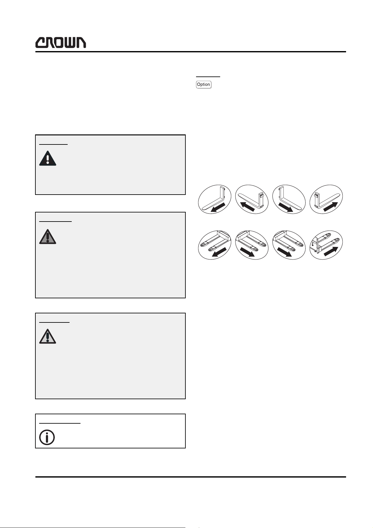
Fork direction
This symbols are used to show the direction of view in
a figure. The direction of the forks is used as reference.
This symbol represents potential minor
injuries and/or potential minor material
damage.
You or other people could be slightly
injured and/or minor material damage
could occur if you fail to comply with
this safety instruction.
Information
This symbol is used with additional information and instructions.
SP 3400 04/2006 • Printed in Germany
MA-0000
Rev. 1 1/06
3
SAFETY
GENERAL SAFETY INSTRUCTIONS
General Safety Instructions
Maintenance and Repair Instructions
Danger!
Observe the safety instructions in the
maintenance manual and the truck operator manual.
Failure to do so could result in serious
or even fatal injuries to maintenance
and other personnel.
Motorised trucks can become hazardous if maintenance and servicing work are neglected. For this reason maintenance and inspections must be performed
at sufficiently short intervals. There must be suitably
trained personnel and proper guidelines at your place
of work.
• Do not allow oils to penetrate the ground or the
drain system. Used oil must be recycled correctly.
Oil filters and dehumidifying inserts must be
treated as special waste. Observe the local authority regulations.
• Immediately neutralize and thoroughly rinse any
spilled battery fluid.
• Keep the truck clean. This will facilitate tracing
loose or faulty components.
• Maintain the legibility of the data capacity plate and
data plate, warning and instruction decals.
• Truck modifications and additions may only be per-
formed with Crown’s prior written approval.
• The reliability, safety and suitability of Crown
trucks can only be ensured by using original Crown
parts.
Maintenance and Repair
•
Always carry out work in accordance with the test
and maintenance schedule enclosed in these
maintenance instructions and any applicable service bulletins.
• Only qualified and authorized personnel may carry
out work on the truck.
• Keep fire protection equipment at hand and do not
use a naked flame to check fluid levels or to test for
leaks.
• Use groundwater neutral, non-flammable solvents
for cleaning. Always perform cleaning work over an
oil separator. Protect the electrical system against
damp.
• Keep the work place and battery charging station
clean, dry and well ventilated.
Before Parking the Truck
•
Brake until the truck comes to rest.
• Lower the fork carriage fully.
• Apply the parking brake.
• Switch off the truck and remove the key.
• When parking on a slope or incline always chock
all wheels.
Before Working on the Truck
•
Jack up the truck so that the drive wheel is clear of
the ground. Apply the Emergency Disconnect and
disconnect the battery.
MA-0000
4
SP 3400 04/2006 • Printed in Germany

• Prevent the truck from rolling away and lowering.
• When working on the mast, fork carriage or lifting
mast always apply a chock to prevent accidental
lowering.
• Allow sufficient room for manoeuvre when testing
the truck, to avoid endangering yourself and other
people.
Before Starting the Truck
•
Test the safety mechanisms.
• Get into the travel position.
SAFETY
GENERAL SAFETY INSTRUCTIONS
• Test the lifting mechanism, travel direction switch,
speed control, steering, warning mechanism and
brakes.
Warning and Instruction Decals on the Truck
In the course of periodic maintenance work, check that
the warning and instruction decals on the truck are
complete and legible.
• Clean any dirty decals.
• Replace any faulty or missing decals.
• A description and the location of the warning and
instruction decals used on the truck are given in
chapter 10.9 of the parts manual.
SP 3400 04/2006 • Printed in Germany
MA-0000
5

Notes:
Printed in Germany
6
SAFETY
CONTROL OF HAZARDOUS ENERGY
Control of Hazardous Energy
In the interest of safety Crown has developed guidelines for proper energy control when performing service and maintenance on the SP 3400.
Before performing any service or maintenance on
the SP 3400, review the appropriate sections in this
service manual for additional procedures to be followed.
In addition, Crown recommends that all mechanics
wear appropriate protective items, such as safety
glasses, work gloves, and steel toed shoes, whenever
performing service or maintenance work on Crown
equipment.
Battery
Warning
[one pound to one US gallon of water] will neutralise acid spilled on clothing, the floor or any other
surface. Apply solution until bubbling stops and
rinse with clean water.
• Keep vent plugs firmly in place at all times except
when adding water or taking hydrometer readings.
• Do not bring any type of flame, spark, etc., near the
battery. Gas formed while the battery is charging is
highly explosive. This gas remains in the cells long
after charging has stopped.
• Do not lay metallic or conductive objects on the
battery. Arcing will result.
• Do not allow dirt, cleaning solution or other foreign
materials to enter cells. Impurities in electrolyte
have a neutralising effect, reducing the available
charge.
Only qualified and experienced personnel should perform maintenance and
repair on batteries.
Follow the battery’s and charger manufacturer’s instructions concerning
practices and procedures for charging,
maintenance and repair.
Safety Rules
• Wear protective clothing such as a rubber apron,
gloves, boots and a full-face shield when performing any maintenance on batteries.
• Do not allow electrolyte to come in contact with
eyes, skin, clothing or floor. If electrolyte comes in
contact with eyes, flush immediately and thoroughly with clean water. Obtain medical attention
immediately.
Make certain the charger being used matches the voltage and amperage of the truck battery. This voltage is
listed on the truck data plate.
Before disconnecting or connecting batteries to a
charger, make sure the charger is “OFF”. If an attempt
is made to do this while the charger is “ON”, serious
injury to you and damage to the battery and charger
could result.
Make sure that the battery used meets the weight, size
and voltage requirements of the truck (refer to data
plate). Never operate the truck with an undersized
battery.
• Should electrolyte be spilled on skin, rinse
promptly with clean water and wash with soap. A
baking soda solution (0.120 kg to 1 litre of water)
SP 3400 04/2006 • Printed in Germany
MA-7534
7
SAFETY
CONTROL OF HAZARDOUS ENERGY
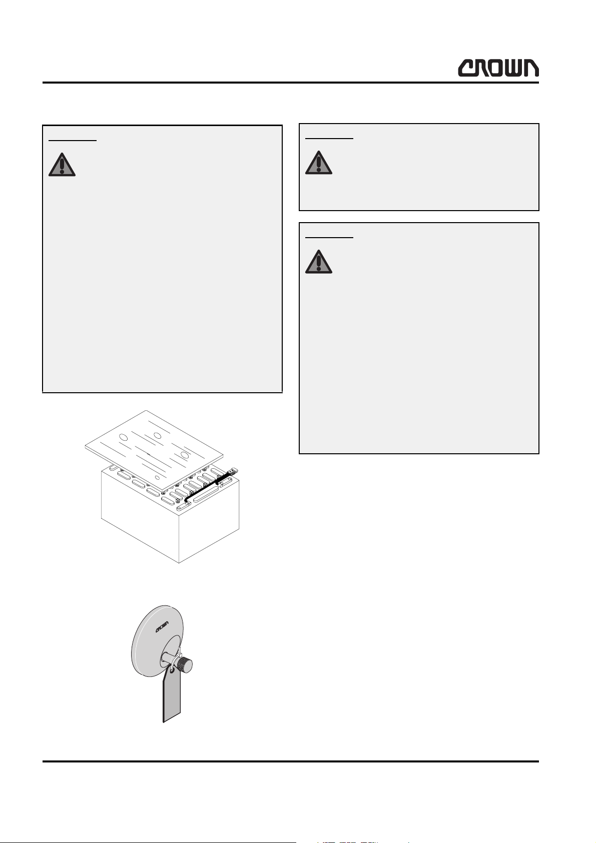
Battery Removal.
Warning
When removing the battery, move truck
to area intended for battery care. Floor
must be level. Turn key switch or toggle switch to “off” position and remove
key. Disconnect battery and lockout or
tagout truck as described in Battery Lockout/Tagout in this section. Never
move battery partially from truck without roller stand in place. Lower load engaging means completely. If battery is
removed with load engaging means
raised, use hoist attached to mast to
provide tipover protection. Do not allow any metallic object to come into
contact with the top of the battery cells.
This may cause a short circuit when removing and transporting the battery.
Use an insulator (such as plywood) to
cover the top of the battery before and
during removal.
Battery Installation
Warning
Make sure that the battery used meets
the weight, size and voltage requirements of the truck (refer to data plate).
NEVER operate truck with an undersized battery.
Warning
When installing the battery, move truck
to area intended for battery care. Floor
must be level. Turn key switch or toggle switch to “off” position and remove
key. Lockout or tagout truck as described in Battery - Lockout/Tagout in
this section. If battery was removed
with load engaging means raised, use
hoist attached to mast to provide
tipover protection. Do not allow any
metallic object to come in contact with
the top of the battery cells. This may
cause a short circuit when transporting
or installing the battery. Use an insulator (such as plywood) to cover the top
of the battery before and during installation.
MA-7534
WARNING
Do not connect
battery to this
vehicle.
Maintenance is
being performed
and vehicle is not
available for
operation.
8251
8262
Lockout - Tagout
Always turn key switch to “off”, remove key and apply
tag to steering wheel or twist grip with cable tie, warning others that the truck is being serviced (Figure
8262).
When maintenance is to be performed and the battery
will be left in the truck:
Disconnect battery, remove the main power fuses and
install a commercially available lockout device on the
battery connector. When maintenance is performed
and the battery is removed from the truck, remove the
main power fuses, install a lockout device on the
truck’s battery connector if possible, or if possible install a tag with a cable tie on the trucks battery connector so it cannot be removed easily, warning that the
truck is not available for operation.
SP 3400 04/2006 • Printed in Germany
8
SAFETY
CONTROL OF HAZARDOUS ENERGY
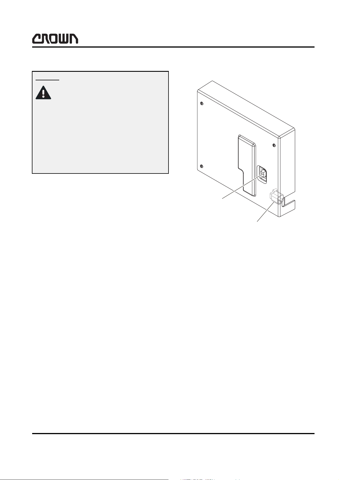
Brake
Danger
Extreme care must be taken when using the Drive/Tow switch to release the
brakes!
The truck will be free-wheeling and the
brake pedal in the operator compartment will have no effect on braking.
Brakes will only be applied when DTS1
is moved from the Tow to the Drive position.
The brakes can be released through the use of the
Drive/Tow switch (DTS1) during a maintenance situation. When using this method to release the brakes,
the truck will not have brakes available for stopping. The truck will not have traction control and
the power steering system will not work.
8. Disconnect brake harness from distribution panel
and connect to original connection, CA407.
DTS1
Brake Harness Connection
PC407
1. Lockout or tagout truck as described in Battery Lockout/Tagout in this section.
2. Chock wheels or make sure truck is secured by
some means to keep it from rolling away.
3. When towing the truck make sure all operators are
informed of the truck’s lack of braking.
4. Move switch DTS1 from the Drive position to the
Tow position.
5. Insert brake harness, PC407, to distribution panel.
6. Move truck to area intended for maintenance.
7. Move DTS1 from the Tow to the Drive position.
Disconnect battery.
12367
SP 3400 04/2006 • Printed in Germany
MA-7534
9
SAFETY
CONTROL OF HAZARDOUS ENERGY
Capacitance
Due to capacitance voltage present in the Access 3
module, whenever performing maintenance which may
permit contact with the bus bars and associated power
cables, discharge the capacitors.
1. Move truck to a secure non traffic maintenance
area with a level floor.
2. Lockout or tagout truck as described in Battery Lockout/Tagout in this section. Disconnect battery.
3. Turn and hold the key switch to the “start” position
for 30 seconds. Voltage lowered below 1 V.
4. Turn key switch to “off”, remove key.
Or allow 5 minutes after battery disconnect for capacitors to discharge.
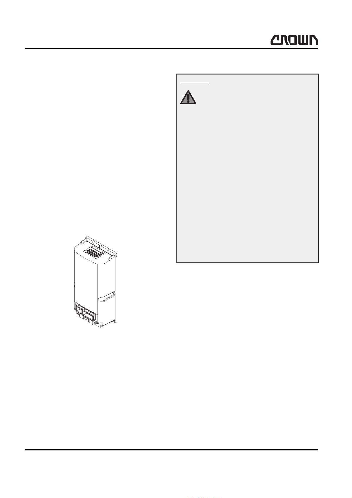
Hydraulic System
Warning
Avoid high pressure fluids!
Escaping fluid under pressure can penetrate the skin causing serious injury.
Relieve pressure before disconnecting
hydraulic lines. Tighten all connections
before applying pressure. Keep hands
and body away from pin holes which
eject fluids under high pressure. Use a
piece of cardboard or paper to search
for leaks. Do not use your hand.
Any fluid injected into the skin under
high pressure should be considered as
a serious medical emergency despite
an initial normal appearance of the
skin. There is a delayed onset of pain,
and serious tissue damage may occur.
Medical attention should be sought immediately by a specialist who has had
experience with this type of injury.
Access 3
Depressurising the hydraulic system
When maintenance is to be performed on the hydraulic
system, to make sure the hydraulic system is not under
pressure:
5. Move truck to a secure non traffic maintenance
¨
12368
area with a level floor.
6. No load on forks.
7. Completely lower load engaging means (mast) or,
if required for maintenance, block mast sections at
appropriate height as described in Mast of this section.
8. Lockout or tagout truck as described in Battery Lockout/Tagout in this section.
9. Open power unit doors and locate the lift manifold.
MA-7534
10
SP 3400 04/2006 • Printed in Germany
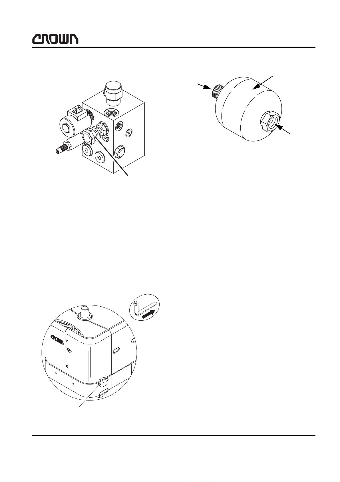
10. Open the manual lower valve to remove hydraulic
pressure.
T
CV3
PCL
MVL
ACC
CV2
C1
PVL
CV1
SAFETY
CONTROL OF HAZARDOUS ENERGY
1
3
2
8266-EU
Manual Lower Valve
12369-EU
Accumulator
The accumulator (hydraulic system shock absorber)
contains a charge of inert gas such as dry nitrogen. Do
not tamper with the gas valve on the accumulator in an
attempt to reduce the amount of this charge. Use accumulator charging equipment and procedures as described in chapter 2 of this manual.
1 Accumulator
2 Hydraulic Line Connection
3Gas Valve
Accumulator
SP 3400 04/2006 • Printed in Germany
10575-EU
MA-7534
11
SAFETY
CONTROL OF HAZARDOUS ENERGY
Lifting and Blocking
Required tools
• Hydraulic Jack
Capacity 3 620 kg (8 000 lbs), Crown part
number: 12259
Minimum collapsed height: 60 mm (2.25 inch)
Maximum raised height: 400 mm (16 inch)
• Jack Stand
Capacity 4 500 kg (10 000 lbs). Commercially
available.
• Appropriately sized hard wood blocks and wedges.
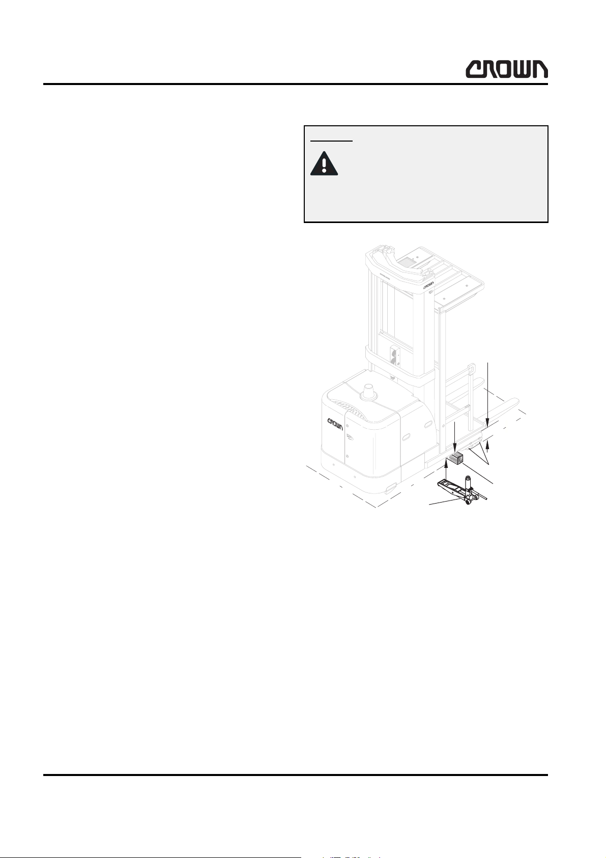
Raising the Side
Danger
Risk of tipover!
Truck stability decreases dramatically
if load wheels are raised more than
13 mm (0.5 inch).
max. 150 mm
(6 inch)
1
2
3
10576-EU
1. Move truck to a secure, traffic-free maintenance
area with a level floor.
2. No load on forks.
3. Raise the platform to max. 150 mm (6 inch) from
floor (Figure 10576-EU).
4. Lockout or tagout truck as described in Battery Lockout/Tagout in this section.
5. Attach a sling and an overhead lifting device to all
cross members of the mast to prevent the truck
from accidental tipping over.
MA-7534
12
SP 3400 04/2006 • Printed in Germany
 Loading...