

Crown SMX-6 Brochure
@crown
* System® Product Reference
®
SMX-6™ Automatic Mixer
ENABLEDSPI
120 VAC
60 Hz
20 W
AUX
CTRL
RS232 / RS422
CROWN BUS
SERIAL DATA LOOP
IN
OUT IN
+–+
INPUT
GROUND
ONLY
–
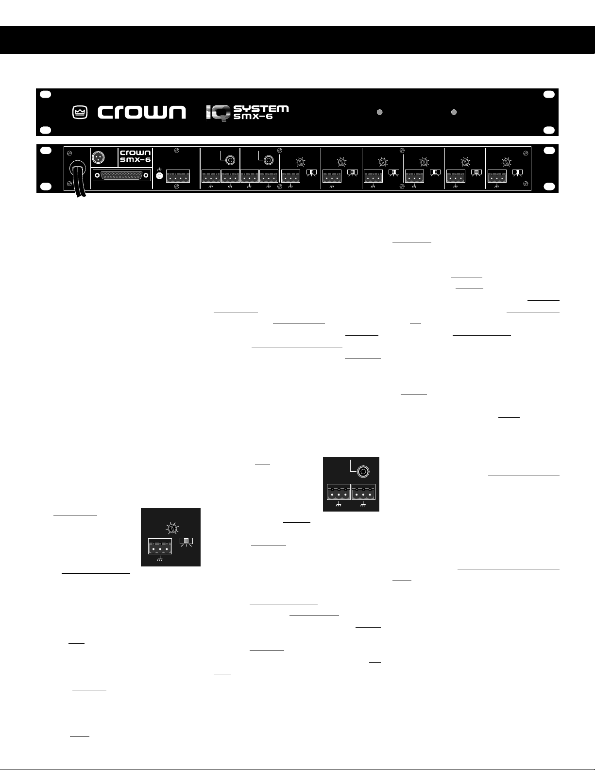
(Front Panel shown above, Rear Panel shown below)
OVERVIEW
What is an SMX-6?
The SMX-6 is a single rack space six by
two automatic mixer designed to be
configured with a computer and appropriate software. Once initially setup the
computer becomes optional. The key to
the ability of the SMX-6 operating as a
stand alone automatic mixer is distributed intelligence™. In an IQ System the
brains of the system live out in the system. This means the audio system is not
going to be lost even if the computer or
communication cables fail. Due to the
modular nature of the SMX-6, multiple
units also may be used together to form
a wider or deeper automated mixer.
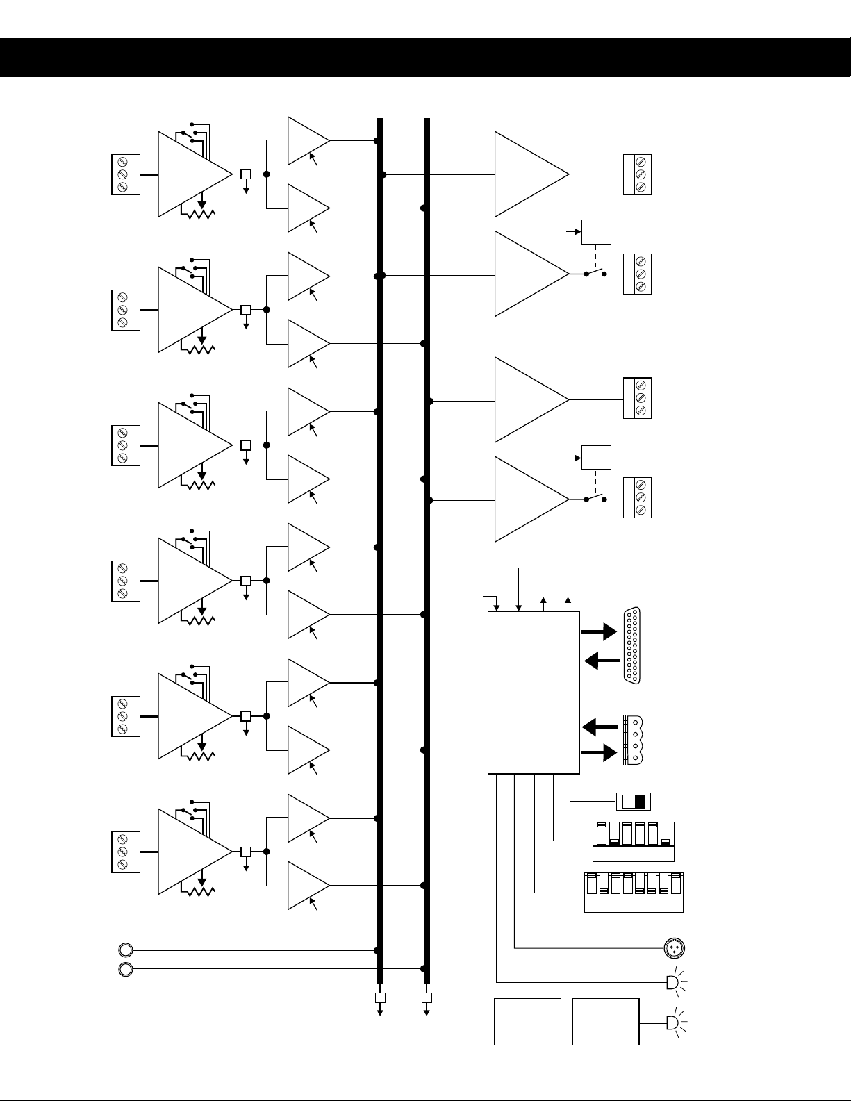
HARDWARE BLOCK DIAGRAM
Refer to the pictures of the front and rear
panels shown above and the block diagram of the SMX-6 mixer on Page 2.
Audio Main Inputs:
Six balanced inputs
with removable 3 pin
barrier block. The
preamp stage includes:
• M/L/P switches
set each input to line level (L) with 0
dB gain, mic level (M) with 25 dB
additional gain, or phantom (P)
which is 25 dB additional gain and
+44 VDC phantom power.
• A trim pot at each input allows for
prefade gain adjustment of –12 dB
to +21 dB gain after the M/L/P
switch.
Prefade sensors at the output of each
preamp stage sense input audio level
just before the input signal is delivered
to the processor controlled VCAs. There
are two VCAs under processor control
AUDIO
IN
-5
-10
1
-12
+–
0
5
ADD 25
FOR MIC
10
15
21
LMP
AUDIO
OUT
2
MAIN
STACK
IN
BUS
AUDIO
OUT
1
MAIN BUS
STACK
IN
AUDIO
IN
6
+–+–+–+–+–
AUDIO
ADD 25
0
5
FOR MIC
-5
10
-10
15
21
-12
LMP
ADD 25
0
5
FOR MIC
IN
-5
10
-10
15
5
21
-12
+– +– +– +– +–
SMX-6 SENSING MIXER
at the output of each sensor. One VCA
controls the gain from input to output mix
1 and the other VCA controls gain from
the input to output mix 2. The net result
is 12 VCAs total, six per output mix.
Audio Stack Inputs:
Two inputs, one per output mix. Connections are via unbalanced RCA phono
jacks. These inputs are op-amp isolated.
There is no processor control of audio
coming into these inputs. The purpose
of the stack inputs is to allow construction of a wide mixer with more than six
inputs by taking the outputs of one mixer
and going into the stack inputs of a second mixer. This means that main inputs
do not have to be used to expand the
effective size of the overall mixer.
Audio Main Outputs:
There are two summing
buses. Each summing
bus provides the out-
AUDIO
OUT
1
MAIN BUS
put mix for the corresponding output channel. Op-amps buffer
the summing bus to the output connection and balance the audio output. The
outputs are via 3 pin removable barrier
blocks.
Audio Bus Outputs:
In addition to the two main outputs, there
are also two bus outputs. Bus outputs 1
and 2 provide the same audio output as
main outputs 1 and 2. Op-amps buffer
the summing bus to the output connection and balance the audio output. What
makes the Bus Outputs different are relays under processor control which may
be used to turn on or off the Bus Output
drive. 3 Pin removable barrier blocks are
used.
Aux Port:
The unit is equipped with a TB-3M type
Page 1 of 5
LMP
STACK
IN
+–+–
AUDIO
IN
4
-5
-10
-12
AUDIO
ADD 25
0
5
FOR MIC
IN
-5
10
-10
15
3
21
-12
LMP
AUDIO
ADD 25
0
5
FOR MIC
IN
-5
10
-10
15
2
21
-12
LMP
AUDIO
ADD 25
0
5
FOR MIC
IN
10
15
1
21
LMP
mini-XLR port. This port may be used to
provide a control signal or sense a control signal.
• Pin 1 is ground reference
• Pin 2 is output under processor
control. When on it provides 10 VDC
at 16 ma. When off it is open collector (high impedance).
• Pin 3 is sensing input. +5 to +30
VDC is sensed as a logic high. The
circuit floats, therefor tie to ground
or TTL source for definite high or low.
Indicators:
A Power light on the front panel indicates
the unit is plugged into AC mains and
AC power is available. A DSPI data signal presence indicator lights to indicate
communication or may be forced on via
processor control.
Crown Bus Port:
The Crown Bus is a serial data loop
where components are connected into
the loop and one component serves as
system interface for all. This unit may
serve as a system interface or may simply operate as a component on a Crown
Bus data loop. Although the Crown Bus
may function on a variety of media,
Crown uses a two-wire 20 ma current
loop for input and output Crown Bus
connections. On this unit connections
are made via 4 pin removable barrier
block. Even if the unit is communicating
directly with a PC via its serial port, it
always functions in software as an addressable component on a Crown Bus
loop. The unit must have a valid loop
address. A valid address is:
• 1 to 250 set via 8 segment DIP
switch
• No other SMX on the same Crown
Bus data loop may have the same
address.
ADD 25
0
5
FOR MIC
-5
10
-10
15
21
-12
LMP
@crown
* System® Product Reference
®
INPUT 1
BALANCED
BUCHANAN
CONNECTOR
INPUT 2
BALANCED
BUCHANAN
CONNECTOR
INPUT 3
BALANCED
BUCHANAN
CONNECTOR
INPUT 4
BALANCED
BUCHANAN
CONNECTOR
INPUT 5
BALANCED
BUCHANAN
CONNECTOR
INPUT 6
BALANCED
BUCHANAN
CONNECTOR
STACK INPUT 1
M/L/P SWITCH
PRE-AMP
GAIN POT
(-12 to +21dB)
M/L/P SWITCH
PRE-AMP
GAIN POT
(-12 to +21dB)
M/L/P SWITCH
PRE-AMP
GAIN POT
(-12 to +21dB)
M/L/P SWITCH
PRE-AMP
GAIN POT
(-12 to +21dB)
M/L/P SWITCH
PRE-AMP
GAIN POT
(-12 to +21dB)
M/L/P SWITCH
PRE-AMP
GAIN POT
(-12 to +21dB)
P = +25dB/+44VDC
M = +25dB
L = 0 dB
INPUT
SENSOR
TO
CPU
P = +25dB/+44VDC
M = +25dB
L = 0 dB
INPUT
SENSOR
TO
CPU
P = +25dB/+44VDC
M = +25dB
L = 0 dB
INPUT
SENSOR
TO
CPU
P = +25dB/+44VDC
M = +25dB
L = 0 dB
INPUT
SENSOR
TO
CPU
P = +25dB/+44VDC
M = +25dB
L = 0 dB
INPUT
SENSOR
TO
CPU
P = +25dB/+44VDC
M = +25dB
L = 0 dB
INPUT
SENSOR
TO
CPU
VCA
1-1
VCA
1-2
VCA
2-1
VCA
2-2
VCA
3-1
VCA
3-2
VCA
4-1
VCA
4-2
VCA
5-1
VCA
5-2
VCA
6-1
VCA
6-2
FROM
CPU
FROM
CPU
FROM
CPU
FROM
CPU
FROM
CPU
FROM
CPU
FROM
CPU
FROM
CPU
FROM
CPU
FROM
CPU
FROM
CPU
FROM
CPU
SUMMING
MIX BUS 1
SUMMING
MIX BUS 2
SENSORS
SENSORS
FROM
OUTPUT
FROM
INPUT
ACTIVE
BALANCE
OUTPUT
AMP
FROM
CPU
ACTIVE
BALANCE
OUTPUT
AMP
ACTIVE
BALANCE
OUTPUT
AMP
FROM
CPU
ACTIVE
BALANCE
OUTPUT
AMP
TO
TO BUS
VCAs
RELAYS
CPU
(MICRO-
PROCESSOR)
MAIN 1
OUTPUT
BALANCED
BUCHANAN
CONNECTOR
BUS 1
BALANCED
RELAY
BUCHANAN
CONNECTOR
BUS 1
OUTPUT
MAIN 2
OUTPUT
BALANCED
BUCHANAN
CONNECTOR
BUS 1
BALANCED
RELAY
BUCHANAN
CONNECTOR
BUS 2
OUTPUT
RS232/RS422 or
Crown Local Net
DB25
CROWN BUS
4-PIN
BUCHANAN
COMMUNICATION
123456
12345678
3-PIN
MINI XLR
STANDARD
BAUD RATE
& PARITY
IQ ADDRESS
AUX PORT
STACK INPUT 2
OUTPUT
SENSOR
TO
CPU
CPU
TO
OUTPUT
SENSOR
MEMORY
BATTERY
BACKUP
SMX-6 Basic Block Diagram
POWER
SUPPLY
(Page 2 of 5)
DSPI
ENABLE
 Loading...