

Crown SC3013, SC3018, SC3016 Service Manual

Service Manual
W artungshandbuch
Manuel de maintenance
SC3000 Series

Printed in Germany
TABLE OF CONTENT

Page intentionally left blank
Seite absichtlich freigelassen
Page intentionellement laissée blanche
Printed in Germany

TABLE OF CONTENT
Table of content
Table of content........................................................................................................................................ IDX-2230-001
MA – SAFETY
Safety Symbols used in the Manual.........................................................................................................MA-2230-001
General Maintenance and Repair Safety Notes....................................................................................... MA-2230-001
Maintenance and Repair ......................................................................................................................MA-2230-001
Before Leaving the Truck.....................................................................................................................MA-2230-002
Before Carrying out Work on the Truck..............................................................................................MA-2230-002
Before Operating the Truck .................................................................................................................MA-2230-002
Warnings and Labels on the Truck .......................................................................................................... MA-2230-002
ITD – INTRODUCTION
Introduction ...............................................................................................................................................ITD-2230-001
General ..................................................................................................................................................ITD-2230-001
Using the Manual..................................................................................................................................ITD-2230-001
Page Numbers ......................................................................................................................................ITD-2230-003
Operating instruction ...........................................................................................................................ITD-2230-003
Service training ....................................................................................................................................ITD-2230-003
Replacement parts orders ...................................................................................................................ITD-2230-003
Truck Data Numbering Sheet ..............................................................................................................ITD-2230-004
Battery Options ....................................................................................................................................ITD-2230-005
M1 – LUBRICATION AND ADJUSTMENT
Lubrication and Adjustment .................................................................................................................. M1.0-2230-001
Access to Components..................................................................................................................... M1.0-2230-001
Jacking up the Truck......................................................................................................................... M1.0-2230-004
Recommended Lubricants and Oils ................................................................................................ M1.1-1710-001
Lubricants....................................................................................................................................... M1.1-1710-001
Cold Store Trucks........................................................................................................................... M1.1-1710-001
Driver Participation ........................................................................................................................... M1.1-1710-001
Daily Maintenance Log...................................................................................................................... M1.1-1710-001
Inspection and Maintenance Schedule............................................................................................ M1.2-2230-001
T or ques .............................................................................................................................................. M1.9-2230-001
M2 – HYDRAULICS
Hydraulic Symbols ................................................................................................................................. M2.0-0000-001
Hydraulic System ................................................................................................................................... M2.1-2230-001
General ............................................................................................................................................... M2.1-2230-001
Operational Description.................................................................................................................... M2.1-2230-003
Idle Mode ....................................................................................................................................... M2.1-2230-003
Priority Valve .................................................................................................................................. M2.1-2230-003
Steering.......................................................................................................................................... M2.1-2230-003
Lifting.............................................................................................................................................. M2.1-2230-003
Tilting.............................................................................................................................................. M2.1-2230-003
Control Valve ..................................................................................................................................... M2.4-2230-001
Main Relief Valve Setting................................................................................................................ M2.4-2230-001
Maintenance and Repairs............................................................................................................... M2.4-2230-001
Pump Motor ....................................................................................................................................... M2.6-2230-001
Hydraulic Pump ................................................................................................................................. M2.6-2230-001
Commissioning............................................................................................................................... M2.6-2230-001
Bleeding ......................................................................................................................................... M2.6-2230-001
Oil Change ......................................................................................................................................... M2.6-2230-001
M3 – DRIVE UNIT
Truck Drive System ................................................................................................................................ M3.0-2230-001
Gear Unit ............................................................................................................................................ M3.0-2230-001
Removal ......................................................................................................................................... M3.0-2230-001
Printed in Germany
01/99
IDX-2230-001

TABLE OF CONTENT
Drive Motor ........................................................................................................................................ M3.0-2230-001
Removal ......................................................................................................................................... M3.0-2230-001
Design ................................................................................................................................................ M3.1-2230-001
Spur wheel bevel gear assembly ................................................................................................. .... M3.1-2230-001
Pre-assembly of the housing with flange shaft ............................................................................... M3.1-2230-001
Bevel gear spur wheel pinion shaft pre-assembly........................................................................... M3.1-2230-001
Spur wheel flange shaft assembly .................................................................................................. M3.1-2230-001
Bevel gear assembly ...................................................................................................................... M3.1-2230-002
Bevel pinion assembly.................................................................................................................... M3.1-2230-002
Flank tooth bearing ........................................................................................................................... M3.1-2230-003
Correcting the flank tooth bearing................................................................................................... M3.1-2230-003
Reducing the installation path of the conical pinion ........................................................................ M3.1-2230-003
Increasing the installation path of the conical pinion ....................................................................... M3.1-2230-003
Maintenance....................................................................................................................................... M3.1-2230-004
Adding oil........................................................................................................................................ M3.1-2230-004
Types of oil ..................................................................................................................................... M3.1-2230-004
Oil level .......................................................................................................................................... M3.1-2230-004
Oil change ...................................................................................................................................... M3.1-2230-004
M4 – ELECTRICS
Electrical System.................................................................................................................................... M4.0-2230-001
Wire Colour Codes ............................................................................................................................ M4.0-2230-001
Abbreviations .................................................................................................................................... M4.0-2230-002
Electrical Symbols ............................................................................................................................ M4.0-2230-004
Electrical Components........................................................................................................................... M4.2-2230-001
Switch Functions............................................................................................................................... M4.2-2230-001
Brake Switch (BRS) ....................................................................................................................... M4.2-2230-001
Encoder (ENC), Encoder Module (EM) .......................................................................................... M4.2-2230-001
Accelerator Pedal Switch (ACS, POT1) ......................................................................................... M4.2-2230-001
Direction Indicator Switch (DIS)...................................................................................................... M4.2-2230-001
Handbrake Switch (HBS) ............................................................................................................... M4.2-2230-001
Raise Potentiometer (POT2) .......................................................................................................... M4.2-2230-001
Steering Axle Potentiometer (POT3) .............................................................................................. M4.2-2230-001
Tilt (TLT), Sideshift (SSS), Auxiliary Switch (AXS).......................................................................... M4.2-2230-001
Emergency Disconnect .................................................................................................................. M4.2-2230-001
Key Switch (KYS)........................................................................................................................... M4.2-2230-001
Fuses (FU) ..................................................................................................................................... M4.2-2230-001
Seat Switch (SES).......................................................................................................................... M4.2-2230-002
Horn Switch (HNS) ......................................................................................................................... M4.2-2230-002
Electrical Components - Overview................................................................................................... M4.2-2230-002
Zapimos B1S 48/700 Controller ............................................................................................................. M4.3-2230-001
General ............................................................................................................................................... M4.3-2230-001
Main Features .................................................................................................................................... M4.3-2230-001
Protective Devices............................................................................................................................. M4.3-2230-001
Polarity Protection .......................................................................................................................... M4.3-2230-001
Wiring Errors .................................................................................................................................. M4.3-2230-001
Overheating.................................................................................................................................... M4.3-2230-001
Protection ....................................................................................................................................... M4.3-2230-001
Key Terms .......................................................................................................................................... M4.3-2230-001
Shunt or Shunt Resistor (+SH/-SH)................................................................................................ M4.3-2230-001
Volt Motor Negative (VMN)............................................................................................................. M4.3-2230-001
Functional Description...................................................................................................................... M4.3-2230-002
Acceleration / Delay Rate ............................................................................................................... M4.3-2230-002
Travel Switch .................................................................................................................................. M4.3-2230-002
Travel Switch Signal Response ...................................................................................................... M4.3-2230-002
Fault Log ........................................................................................................................................ M4.3-2230-002
Fault Identification .......................................................................................................................... M4.3-2230-002
Sparkless Contactors ..................................................................................................................... M4.3-2230-002
IDX-2230-002
Printed in Germany
01/99

TABLE OF CONTENT
Inversion Braking............................................................................................................................ M4.3-2230-002
Creep Mode.................................................................................................................................... M4.3-2230-002
Slow Travel ..................................................................................................................................... M4.3-2230-002
Steering Controller ......................................................................................................................... M4.3-2230-002
45° Steering Angle.......................................................................................................................... M4.3-2230-003
MOSFET ........................................................................................................................................ M4.3-2230-003
Pedal Braking (Inversion Braking with Battery Supply Regeneration)............................................. M4.3-2230-003
Pulse Width Modulation (PWM)...................................................................................................... M4.3-2230-003
Ramp Start ..................................................................................................................................... M4.3-2230-003
Key Switch ..................................................................................................................................... M4.3-2230-003
Self Test ......................................................................................................................................... M4.3-2230-003
Inverse Travel Alarm....................................................................................................................... M4.3-2230-003
Seat Switch .................................................................................................................................... M4.3-2230-003
Current Limit................................................................................................................................... M4.3-2230-003
Overvoltage.................................................................................................................................... M4.3-2230-003
Overheating.................................................................................................................................... M4.3-2230-003
Low V oltage Reduction................................................................................................................... M4.3-2230-003
ZAPIMOS B1S 48/700 Traction Controller Connections................................................................. M4.3-2230-004
Programmer Connection "B" .......................................................................................................... M4.3-2230-005
Status LED "A" ............................................................................................................................... M4.3-2230-005
Status LED Diagnosis .................................................................................................................... M4.3-2230-005
Control Line Connections................................................................................................................. M4.3-2230-006
Traction Controller .......................................................................................................................... M4.3-2230-006
ZAPIMOS B1S 48/700 Pin Layout ..................................................................................................... M4.3-2230-007
Maintenance....................................................................................................................................... M4.3-2230-008
Cleaning the Traction Controller ..................................................................................................... M4.3-2230-008
Removing / Installing the Traction Controller ................................................................................. M4.3-2230-008
To remove ...................................................................................................................................... M4.3-2230-008
Installing the Traction Controller ..................................................................................................... M4.3-2230-009
Zapimos HP 350A Pump Controller ...................................................................................................... M4.3-2230-200
General ............................................................................................................................................... M4.3-2230-200
Protective Devices............................................................................................................................. M4.3-2230-200
Polarity Protection .......................................................................................................................... M4.3-2230-200
Wiring Errors .................................................................................................................................. M4.3-2230-200
Overheating.................................................................................................................................... M4.3-2230-200
Protection ....................................................................................................................................... M4.3-2230-200
Key Terms .......................................................................................................................................... M4.3-2230-200
Shunt or Shunt Resistor (+SH/-SH)................................................................................................ M4.3-2230-200
Volt Motor Negative (VMN)............................................................................................................. M4.3-2230-200
Functional Description...................................................................................................................... M4.3-2230-201
Acceleration / Delay Rate ............................................................................................................... M4.3-2230-201
Current Limit................................................................................................................................... M4.3-2230-201
Fault Identification .......................................................................................................................... M4.3-2230-201
Fault Log ........................................................................................................................................ M4.3-2230-201
Hydraulic Function Switch .............................................................................................................. M4.3-2230-201
Key Switch ..................................................................................................................................... M4.3-2230-201
Lift Cut-Out ..................................................................................................................................... M4.3-2230-201
Lift Potentiometer ........................................................................................................................... M4.3-2230-201
Lift Potentiometer Response .......................................................................................................... M4.3-2230-201
Low V oltage Reduction................................................................................................................... M4.3-2230-201
MOSFET ........................................................................................................................................ M4.3-2230-201
Overheating.................................................................................................................................... M4.3-2230-201
Overvoltage.................................................................................................................................... M4.3-2230-201
Pulse Width Modulation (PWM)...................................................................................................... M4.3-2230-201
Seat Switch .................................................................................................................................... M4.3-2230-202
Self Test ......................................................................................................................................... M4.3-2230-202
Steer Support ................................................................................................................................. M4.3-2230-202
Printed in Germany
01/99
IDX-2230-003

TABLE OF CONTENT
ZAPIMOS HP 350 A Pump Controller Connections ....................................................................... M4.3-2230-202
Programmer Connection "B" .......................................................................................................... M4.3-2230-203
Status LED "A" ............................................................................................................................... M4.3-2230-203
Status LED Diagnosis .................................................................................................................... M4.3-2230-203
ZAPIMOS HP 350 A Pin Layout........................................................................................................ M4.3-2230-204
Maintenance....................................................................................................................................... M4.3-2230-204
Cleaning the Pump Controller......................................................................................................... M4.3-2230-204
Removing / Installing the Pump Controller ..................................................................................... M4.3-2230-205
To remove ...................................................................................................................................... M4.3-2230-205
Installing the Pump Controller......................................................................................................... M4.3-2230-205
Programmer ............................................................................................................................................ M4.4-2230-001
General ............................................................................................................................................... M4.4-2230-001
Connecting the Programmer ............................................................................................................ M4.4-2230-003
Operating Menu ................................................................................................................................. M4.4-2230-003
General .......................................................................................................................................... M4.4-2230-003
T raction Controller Operating Menu ................................................................................................ M4.5-2230-001
Programmer Start Routine................................................................................................................ M4.5-2230-002
Traction Controller Menu Functions ..................................................................................................... M4.5-2230-003
PROGRAM Menu ............................................................................................................................... M4.5-2230-004
TESTER Menu.................................................................................................................................... M4.5-2230-005
ALARMS Menu................................................................................................................................... M4.5-2230-006
PROGRAM PEDAL Menu .................................................................................................................. M4.5-2230-007
CONFIG Menu .................................................................................................................................... M4.5-2230-008
Pump Controller Operating Menu .................................................................................................... M4.5-2230-009
Menu Functions Pump Controller ......................................................................................................... M4.5-2230-010
PROGRAM Menu ................................................................................................................................M4.5-2230-011
TESTER Menu.................................................................................................................................... M4.5-2230-012
ALARMS Menu................................................................................................................................... M4.5-2230-013
PROGRAM VACC Menu .................................................................................................................... M4.5-2230-014
CONFIG Menu .................................................................................................................................... M4.5-2230-015
Traction Controller Safety Test............................................................................................................ M4.20-2230-001
Pulse Monitor Trip T est (PMT) ........................................................................................................ M4.20-2230-001
Equipment .................................................................................................................................... M4.20-2230-001
T est .............................................................................................................................................. M4.20-2230-001
PMT Safety Test Wiring................................................................................................................... M4.20-2230-002
Battery ................................................................................................................................................... M4.25-2230-001
General ............................................................................................................................................. M4.25-2230-001
Operation ......................................................................................................................................... M4.25-2230-001
Reading the Electrolyte Level......................................................................................................... M4.25-2230-001
Replacing the Battery...................................................................................................................... M4.25-2230-001
Removing the Battery ..................................................................................................................... M4.25-2230-001
Charging the Battery ....................................................................................................................... M4.25-2230-001
Battery Discharge Indicator (BDI) ....................................................................................................... M4.30-2230-001
General ............................................................................................................................................. M4.30-2230-001
Adjusting the Battery Discharge Indicator .................................................................................... M4.30-2230-001
Traction / Pump Motor Maintenance ................................................................................................... M4.35-2230-001
Access.............................................................................................................................................. M4.35-2230-001
M5 – BRAKE
Brake System.......................................................................................................................................... M5.0-2230-001
General ............................................................................................................................................... M5.0-2230-001
Operation ........................................................................................................................................... M5.0-2230-001
Replacing the Brake Disks and Linings........................................................................................... M5.0-2230-002
Preparation..................................................................................................................................... M5.0-2230-002
Brake Disk and Lining Dimensions ................................................................................................. M5.0-2230-003
Removing the Brake Disks and the Friction Plates (Fig. M0362).................................................... M5.0-2230-004
Installation ...................................................................................................................................... M5.0-2230-004
Removing the Handbrake Cable (Fig.M0366)................................................................................. M5.0-2230-006
Installation ...................................................................................................................................... M5.0-2230-006
Printed in Germany
01/99
IDX-2230-004

TABLE OF CONTENT
Adjusting the Operating Brake and Handbrake .............................................................................. M5.0-2230-006
Preparation..................................................................................................................................... M5.0-2230-006
Adjusting the Operating Brake Air Gap........................................................................................... M5.0-2230-006
Operating Brake Test ........................................................................................................................ M5.0-2230-007
Handbrake Adjustment ..................................................................................................................... M5.0-2230-007
M6 – STEERING
Steering ................................................................................................................................................... M6.0-2230-001
Hydraulic System .............................................................................................................................. M6.0-2230-001
Components ...................................................................................................................................... M6.0-2230-001
Removing the Steering Motor .......................................................................................................... M6.0-2230-002
Steering System Hydraulic Diagram................................................................................................ M6.0-2230-002
Steering Axle........................................................................................................................................... M6.1-2230-001
Design ................................................................................................................................................ M6.1-2230-001
Steering Drive Assembly .................................................................................................................. M6.1-2230-001
Wheel hub pre-assembly................................................................................................................ M6.1-2230-001
Steering knuckle pre-assembly ...................................................................................................... M6.1-2230-001
Steering knuckle and wheel hub assembly..................................................................................... M6.1-2230-001
Spur pinion wheel shaft pre-assembly............................................................................................ M6.1-2230-002
Housing Pre-Assembly................................................................................................................... M6.1-2230-002
Setting the Bearing Play ................................................................................................................. M6.1-2230-003
Cylinder Pre-Assembly................................................................................................................... M6.1-2230-006
Fitting the Cylinders........................................................................................................................ M6.1-2230-006
Assembling the Axle Bracket to the Steering Drive......................................................................... M6.1-2230-006
Operational and Leak Test.............................................................................................................. M6.1-2230-006
Maintenance....................................................................................................................................... M6.1-2230-007
General .......................................................................................................................................... M6.1-2230-007
Gear Lubricant................................................................................................................................ M6.1-2230-007
Seals .............................................................................................................................................. M6.1-2230-007
M7 – MAST
Mast ......................................................................................................................................................... M7.0-2230-001
Disassembly ...................................................................................................................................... M7.0-2230-001
Mast Roller Adjustment .................................................................................................................... M7.0-2230-001
Fork Carriage Roller Adjustment...................................................................................................... M7.0-2230-003
Mast Roller Adjustment .................................................................................................................... M7.0-2230-004
Checking the Mast Play .................................................................................................................... M7.0-2230-004
Lift Chain Test......................................................................................................................................... M7.5-2230-001
General ............................................................................................................................................... M7.5-2230-001
Maintenance....................................................................................................................................... M7.5-2230-001
Detailed Chain Testing ...................................................................................................................... M7.5-2230-002
Worn or Missing Plates................................................................................................................... M7.5-2230-002
Pitting and Corrosion ...................................................................................................................... M7.5-2230-002
Protruding or Turned Chain Pins .................................................................................................... M7.5-2230-002
Freedom of Movement and Worn Edges........................................................................................ M7.5-2230-002
Measuring the Chain Elongation..................................................................................................... M7.5-2230-003
Chain T ension................................................................................................................................. M7.5-2230-003
Chain Anchor and Pulleys .............................................................................................................. M7.5-2230-003
Fork Tine Test .................................................................................................................................... M7.6-2230-001
General .......................................................................................................................................... M7.6-2230-001
Fork Identification ........................................................................................................................... M7.6-2230-001
Repairs........................................................................................................................................... M7.6-2230-001
Crack Inspection............................................................................................................................. M7.6-2230-001
V erticality Test ................................................................................................................................ M7.6-2230-002
Fork Blade Warping........................................................................................................................ M7.6-2230-002
Measuring the Fork Tip Width......................................................................................................... M7.6-2230-003
Fork Tine Height Difference ............................................................................................................ M7.6-2230-003
Fork Stop........................................................................................................................................ M7.6-2230-003
Wear............................................................................................................................................... M7.6-2230-004
Printed in Germany
01/99
IDX-2230-005

TABLE OF CONTENT
M8 – CYLINDERS
Cylinders ................................................................................................................................................. M8.0-2230-001
General ............................................................................................................................................... M8.0-2230-001
Plunger Cylinders (Single-Acting Cylinders) .................................................................................. M8.0-2230-001
Piston Cylinder (Double-Acting Cylinder) ....................................................................................... M8.0-2230-002
Maintenance....................................................................................................................................... M8.0-2230-004
Inspection .......................................................................................................................................... M8.0-2230-004
Installing the Piston Seal .................................................................................................................. M8.0-2230-005
General .......................................................................................................................................... M8.0-2230-005
Rod Seal Disassembly Tool............................................................................................................ M8.0-2230-005
Assembly of Small Rod Seals ........................................................................................................ M8.0-2230-005
Assembly of Large Rod Seals ........................................................................................................ M8.0-2230-005
DIA – ELECTRICAL DIAGRAMS
Key............................................................................................................................................................. DIA-2230-001
Connectors .......................................................................................................................................... DIA-2230-001
Contactors ........................................................................................................................................... DIA-2230-001
Abbreviations ...................................................................................................................................... DIA-2230-001
Control Circuit .......................................................................................................................................... DIA-2230-002
Power Circuit ............................................................................................................................................ DIA-2230-003
Connectors ............................................................................................................................................... DIA-2230-004
Traction Controller .............................................................................................................................. DIA-2230-004
Pump Controller .................................................................................................................................. DIA-2230-005
Seat Switch and Steer Pot .................................................................................................................. DIA-2230-006
Control Levers ..................................................................................................................................... DIA-2230-007
B.D.I., Horn and Brake Switches ........................................................................................................ DIA-2230-008
Steer Column ....................................................................................................................................... DIA-2230-009
Star Points ................................................................................................................................................ DIA-2230-010
Panel Wiring.............................................................................................................................................. DIA-2230-011
Power Cables ............................................................................................................................................ DIA-2230-012
Part Numbers for Connectors and Looms ............................................................................................. DIA-2230-013
ZAPI Connectors ................................................................................................................................. DIA-2230-013
MOLEX Connectors............................................................................................................................. DIA-2230-013
DEUTSCH Connectors ........................................................................................................................ DIA-2230-013
Looms .................................................................................................................................................. DIA-2230-013
HYD – HYDRAULIC SCHEMATIC
Hydraulic Schematic ...............................................................................................................................HYD-2230-001
IDX-2230-006
Printed in Germany
01/99

Printed in Germany
SAFETY

Page intentionally left blank
Seite absichtlich freigelassen
Page intentionellement laissée blanche
Printed in Germany
SAFETY
Safety Symbols used in the
Manual
To help guide you through the manual and to highlight
particular danger areas, we have used graphic illustrations:
DANGER
This symbol indicates life-threatening risks
l
Failure to comply with this notice may
result in severe or fatal injuries to
yourself or other people.
WARNING
This symbol indicates the risk of serious
injury and/or serious material damage.
l
Failure to comply with this notice may
result in severe injuries to yourself or
other people and/or serious material
damage.
General Maintenance and Repair Safety Notes
DANGER
Read the safety notices in the truck
Maintenance and Operator's Manuals.
l
Failure to do so could result in severe or
fatal injuries to maintenance personnel
and/or other persons.
Motorised vehicles can be dangerous if maintenance
and service are neglected. For this reason maintenance
and inspections must be carried out at regular short
intervals by trained personnel working to approved
company guidelines.
Maintenance and Repair
1. Maintenance work must only be carried out in
accordance with the test and maintenance program
contained in the present Maintenance Manual and any
applicable service notices.
CAUTION
This symbol indicates the risk of minor
injury and/or minor material damage.
l
Failure to comply with this notice may
result in minor injuries to yourself or
other people and/or minor material
damage.
INFORMATION
Contains additional information with
supplementary notes and hints.
OPTION
OPTION
These items relate to optional features not
supplied with the standard version.
2. Only qualified and authorised personnel may carry
out work on the truck.
3. Always k eep fire extinguishers in good working
condition. Do not approach fluid levels or leaks with a
naked flame.
4. To clean, use a non flammable, non combustable
cleaning solution which is groundwater-neutral.
Only carry out cleaning with an oil separator.
Protect the electrical system from dampness.
5. Keep the service area clean, dry and well-ventilated.
6. Do not allow oil to penetrate the ground or enter the
draining system. Used oil must be recycled. Oil filters
and desiccants must be treated as special waste
products. Relevant applicable regulations must be
followed.
7. Neutralise and thoroughly rinse any spilled battery
fluid immediately .
8. Keep the truck clean. This will facilitate the location
of loose or faulty components.
9. Make sure that capacity and data plates, warnings
and labels are legible at all times.
Printed in Germany
REV .1 10/99
MA-2230-001
1

SAFETY
10. Alterations or modifications b y the o wner or
operator are not permitted without the express written
authorisation from Crown.
11. Only use original Crown spare parts to ensure the
reliability, safety and suitability of the Crown truck.
Before Leaving the Truck
l
l
l
l
l
Stop the truck.
Lower the f ork carriage fully.
Apply the parking brake.
Turn off the travel switch and remove the
key.
Block all wheels when parking on an uneven
surface.
Before Carrying out Work on the Truck
l
Raise the truck to free the drive wheel.
Press the Emergency Stop button and
disconnect the battery.
Warnings and Labels on the Truck
l
l
l
The order and meaning of the warnings and labels on
the truck are described in section 10.9 of the parts
manual.
During regular maintenance check that the
warnings and labels on the truck are
complete and legible.
Clean any illegible labels.
Replace any faulty or missing labels.
l
l
l
Prevent the truck from rolling away.
Before carrying out work on the hoist frame,
the lift mast or on the fork carriage:
Block these parts according to maintenance
instructions in order to prevent them from
dropping.
Only carry out operational testing when there
is sufficient room to manoeuvre, to avoid the
risk of injury to yourself and others.
Before Operating the Truck
l
l
l
Check the safety devices.
Get into the driver's seat.
Check the operation of the lifting device,
travel direction switch, speed control,
steering, warning devices and brakes.
MA-2230-002
2
Printed in Germany
01/99

Printed in Germany
INTRODUCTION

Page intentionally left blank
Seite absichtlich freigelassen
Page intentionellement laissée blanche
Printed in Germany

Introduction
INFORMATION
THIS BOOK IS NOT AN OPERATING MANUAL. IT IS DESIGNED FOR SPECIALIST
PERSONNEL WHO HAVE BEEN TRAINED
AND AUTHORISED BY CROWN FOR THE
WORK DESCRIBED HEREIN.
This manual therefore contains fewer and less detailed
danger warnings than the Operator's Manual, as the latter
is aimed at persons who have very little or no prior
experience at all.
General
The present manual is designed for Customer Service
engineers who wish to familiarise themselves with the
maintenance work required for the various truck
components.
It also contains troubleshooting sections which can be
used to identify and remedy truck faults.
INTRODUCTION
Using the Manual
The Maintenance Manual is written in three independent
language blocks:
Each language block in turn is divided into chapters and
sections. The page numbers in the Maintenance Section
are preceeded by an M.
The table on the following page shows how the manual is
structured.
English, German and French
.
Printed in Germany
01/99
ITD-2230-001
1
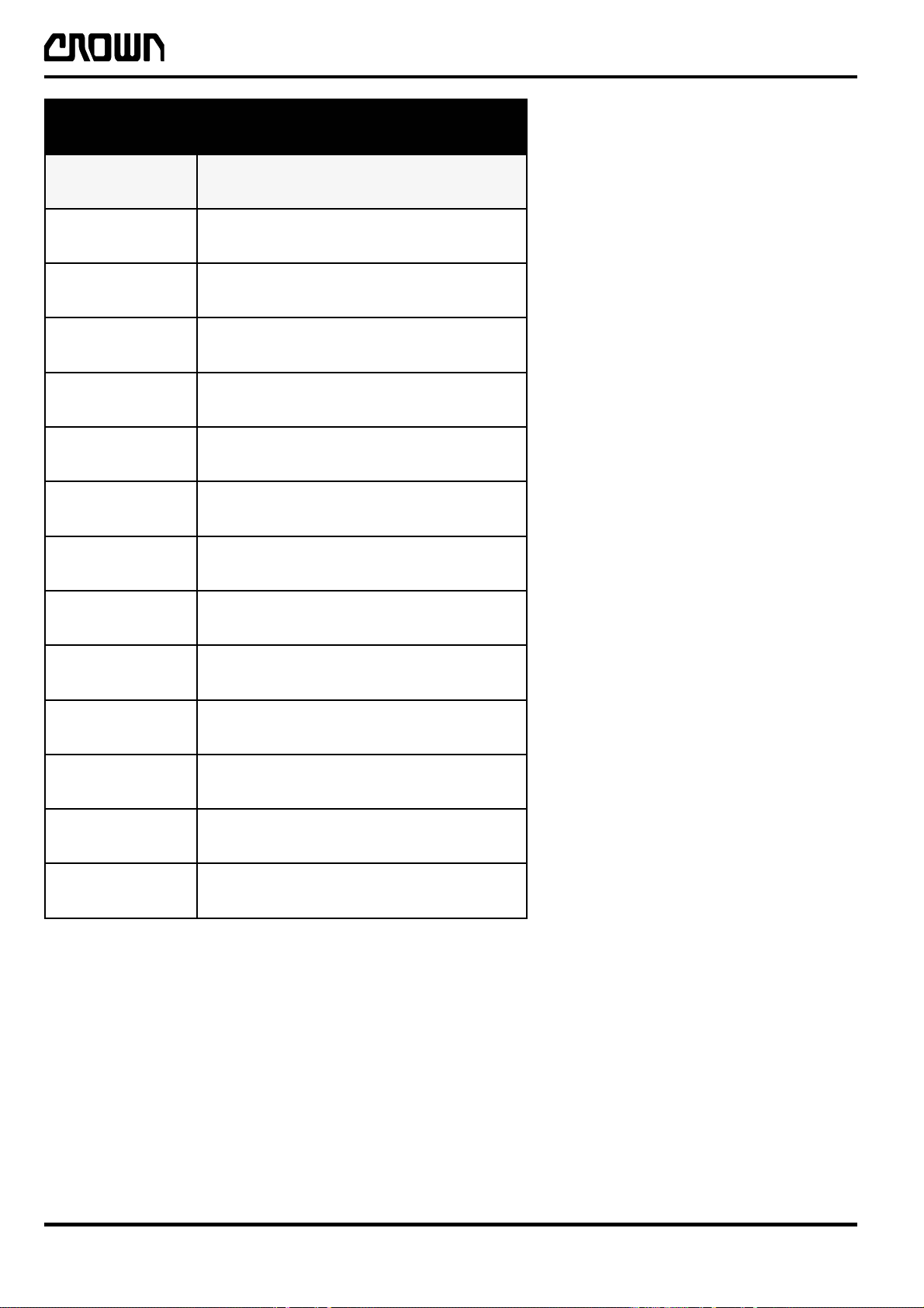
noitceS noitpircseD
XDItnetnoCfoelbaT
AMytefaS
DTInoitcudortnI
1MtnemtsujdAdnanoitacirbuL
2MsciluardyH
INTRODUCTION
ecnanetniaMsnoitceS
3MtinUevirD
4MlacirtcelE
5MekarB
6MgnireetS
7MtsaM
8MrednilyC
AIDsmargaiDlacirtcelE
DYHcitamehcSciluardyH
ITD001B-gb
2
ITD-2230-002
Printed in Germany
01/99

Page Numbers
The page numbers are located on the lower left and right
hand margins of each page and have the following form:
M1.1-2230-001 X
INTRODUCTION
M = Maintenance
Chapter
Section
z. B. 1.2 = Inspection and
Maintenance Plan
Operating instruction
This manual contains no operating instructions. An
operating instructions manual is supplied with the vehicle.
Additional copies can be ordered as required.
With the help of this manual you and your personnel will
be able to ensure the long service life, operational safety
and error free functioning of your CROWN vehicle.
Service training
CROWN offers the appropriate vehicle related training
for service personnel. Details on this training can be
obtained from CROWN on request.
Identical for each language
Section is only once in the manual
Page number
Truck code
Replacement parts orders
When ordering spare parts from this manual please
always give the full description of the vehicle model as
well as the order number. These details enable us to
process your orders in an accurate, quick and reliable
way.
Please refer to the Technical Specifications Sheet for the
utilisable loads, technical data and dimensions for this
series.
Brochures can be obtained from your CROWN dealer or
from the following address:
CROWN Gabelstapler GmbH
Moosacher Str. 52
D-80809 München
T el.: 089/93 00 20
Fax: 089/93 00 2-175
Printed in Germany
01/99
ITD-2230-003
3

Truck Data Numbering Sheet
1.3SCTL–2–2
INTRODUCTION
Capacity
1.3 = 1250 kg
1.6 = 1600 kg
1.8 = 1800 kg
Model designation
SC = Sitdown Rider
Counterbalance
T = Telescopic
L = Double, part free lift
F = Double, full free lift
T = Triple, full free lift
NOTE
FOR SPECIALS USE THE ACTUAL FIGURES
FOR COLLAPSED / LIFT HEIGHT AND FORK
LENGTH (SEE TABLES ITD002-GB AND
ITD.003-GB).
Example:
Truck with data 1.3SCTL-2-2 designates
l
Capacity 1250 kg
l
Sitdown Rider Counterbalance
l
Telescopic double part free lift mast
l
Collapsed height 1970 mm
l
Lift height 2880 mm
l
Fork length 1000 mm
htgneLkroF
hsaD mm
1009
20001
30511
40021
50221
6006
7008
80731
97601
ITD002-gb
/)mm(thgieHdespalloC
)mm(thgieHgnitfiL
hsaD FTCS/LTCS
10642/0571
20882/0791
30723/5612
40753/5132
50783/5642
60724/5662
70264/0482
80105/5303
90265/0433
010195/5843
hsaD TTCS
10763/0671
20034/0791
35884/5612
45335/5132
55875/5642
65836/5662
70196/0482
85947/5303
98634/3991
011254/4402
116284/5412
2131906/9652
4
ITD-2230-004
ITD003-gb
Printed in Germany
01/99
INTRODUCTION
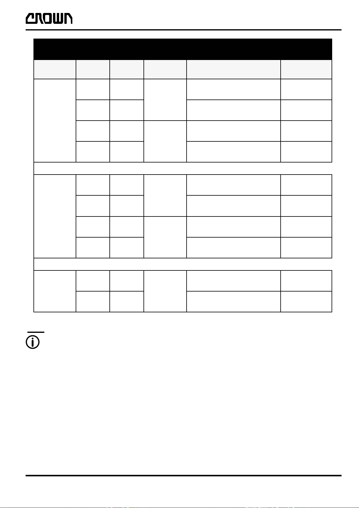
snoitpOyrettaB
ledoM noitpO hA
1noitpO
h1noitpO
3103CS
2noitpO
h2noitpO
2noitpO
h2noitpO
6103CS
3noitpO
h3noitpO
)mm( )mm(A13534NID
003
063
7811
063
564
004
084
5921
084
026
004
084
5921
084
026
005
006
3041
006
577
726x538x814
726x538x814
487x538x814
487x538x814
726x538x625
726x538x625
487x538x625
487x538x625
726x538x625
726x538x625
487x538x625
487x538x625
726x538x436
726x538x436
487x538x436
487x538x436
epyT
DS
DHS
DS
DHS
DS
DHS
DS
DHS
DS
DHS
DS
DHS
DS
DHS
DS
DHS
3noitpO
005
006
8103CS
h3noitpO
NOTE
ALWAYS SPECIFY MODEL NO. WHEN
ORDERING SPARE PARTS.
Spare parts for model SC3013 option 2/2h
correspond to model SC3016 option 2/2h.
Spare parts for model SC3016 option 3/3h
correspond to model SC3018 option 3/3h.
006
577
726x538x436
726x538x436
3041
487x538x436
487x538x436
DS
DHS
DS
DHS
ITD004-gb
Printed in Germany
01/99
ITD-2230-005
5

Page intentionally left blank
Seite absichtlich freigelassen
Page intentionellement laissée blanche
Printed in Germany

LUBRICATION AND ADJUSTMENT
Printed in Germany

Page intentionally left blank
Seite absichtlich freigelassen
Page intentionellement laissée blanche
Printed in Germany
Lubrication and Adjustment
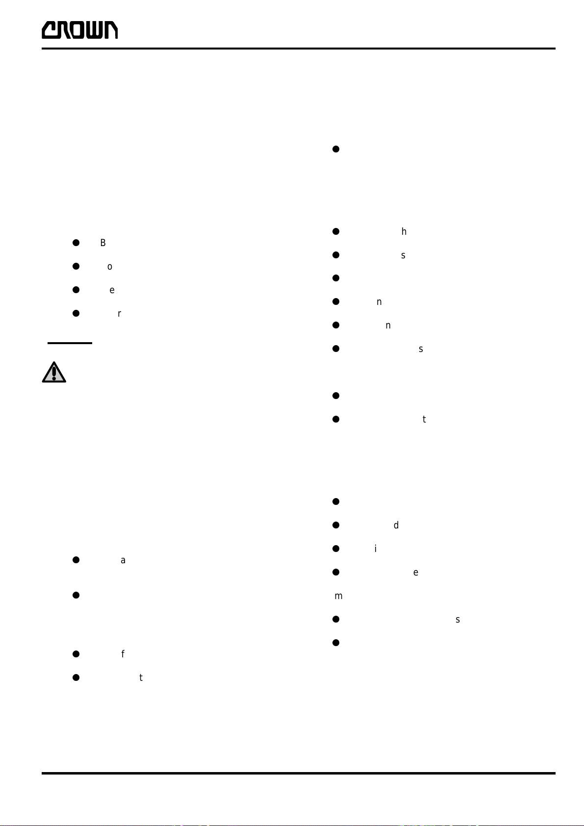
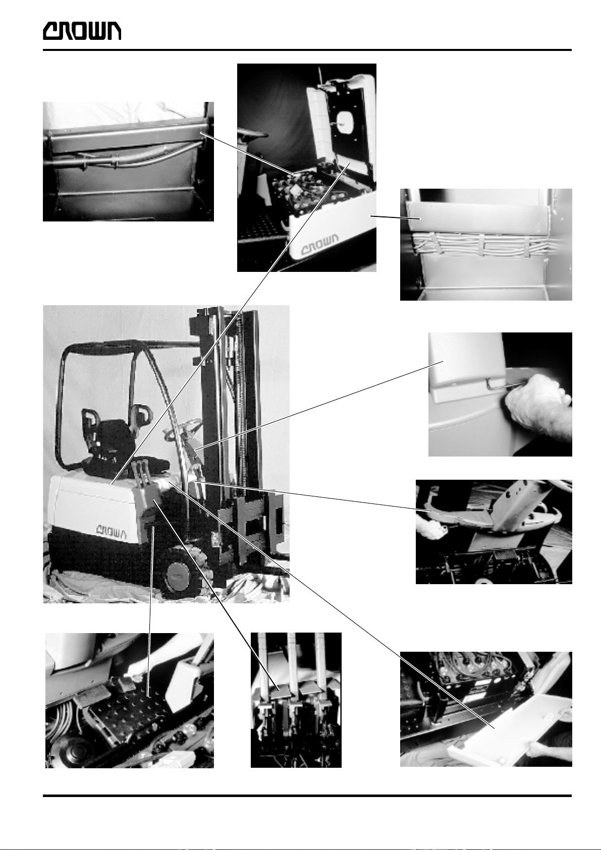
Access to Components
MAINTENANCE
In the course of regular maintenance the contactor panel,
drive unit, hydraulic system and electrical components
in the chassis can be reached by removing or opening
the panels.
Fig. B: Battery compartment lid
Provides access to:
l
Battery
l
Contactor panel including impulse controls
l
Steering axle and potentiometer
l
Hydraulic motor and pump
CAUTION
WHEN THE BATTERY COMPARTMENT LID
IS OPENED IT CAN TIP OVER IF THE LID
CENTRE OF GRAVITY MOVES OVER THE
PIVOT POINT / ATTACHMENT POINT OF
THE LID.
Fig. C: LH and RH panels (LH illustrated)
l
Lift the side panel out of the attachment
Fig. D: Steering column front panel
Provides access to:
l
Key switch
l
Direction switches
l
Encoder
l
Wiring
l
Steering unit and distributor block
l
Hydraulic lines
To remove:
l
Loosen two hex. socket screws
l
Lift panel slightly and lever out at the bottom
Access:
Pull the handle on the front of the lid and open the
battery compartment lid.
Figs. B1 and B2
Provides access to:
l
Hydraulic lines (Fig. B1) on the right hand side
of the battery compartment.
l
Cable duct (Fig. B2) on the left hand side
of the battery compartment.
Access:
l
Lift off the side panel
l
Remove the battery
Fig. E: Inner dashboard
Provides access to:
l
Handbrake
l
Battery display
l
Wiring
l
Hydraulic lines
To remove:
l
Loosen 6 hex. socket screws
l
Remove panel
Printed in Germany
01/99
M1.0-2230-001
1

MAINTENANCE
Fig. F: Valve and Control Handle Panel
Provides access to:
l
Valve block
l
Switch, potentiometer
l
Control handle mechanism
To remove:
l
Remove the base plate
l
Loosen the two hex. socket screws at the rear
upper section.
l
Remove the single hex. socket screw at the
front below the base plate
l
Lift up the panel
Fig. G: LH and RH base plate (RH illustrated)
Provides access to:
l
Brake pedal and mechanism
l
Brake
l
Accelerator pedal / travel switch and
potentiometer
l
Tilt cylinder attachment (frame)
l
Valve block hydraulic lines
l
Wiring
l
LH and RH drive motor
To remove:
l
Loosen the single hex. socket screw on the
RH base plate
l
Lift out the LH and RH base plates.
2
M1.0-2230-002
Printed in Germany
01/99
MAINTENANCE
B1
M0258
B
M0251
B2
D
M0252
M0257
A
Printed in Germany
M0116
M0253 M0256
01/99
E
CFG
M1.0-2230-003
M0254b
M0259
3
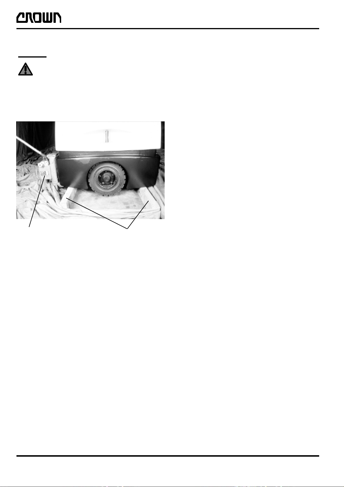
Jacking up the Truck
WARNING
ALWAYS SUPPORT A RAISED TRUCK WITH
WOODEN BLOCKS OR OTHER
APPROPRIATE EQUIPMENT TO RELIEVE
THE JACK.
Apply the jack as shown in Fig. M0262. The same
procedure is used for raising the front section of the truck.
MAINTENANCE
Jack
M0262
Wooden
blocks
4
M1.0-2230-004
Printed in Germany
01/99

Recommended Lubricants and Oils
Lubricants
Only high grade lubricants and oils should be used. These can be obtained from any oil manufacturer . Those listed
on the following page are typical, and any lubricant of the
same grade can be used.
Cold Store Trucks
Special hydraulic oil, lubrication oil and grease must be
used for cold store trucks operating in low temperature
conditions (see table on page M1.1-1710-002). An anticorrosion fluid (Crown no. 078882-002) must be applied
to all screws, washers, nuts, pins, retaining rings etc.
Maintenance schedules should be kept as short as
possible to prevent excessive wear of moving
components.
Driver Participation
MAINTENANCE
By involving the driver in the maintenance schedule, truck
downtimes can be substantially reduced. The driver can
also contribute to determining the maintenance schedule,
thereby saving costs. Crown therefore recommends that
the driver carry out the daily maintenance in accordance
with the table on page M1.2-2230-002.
Daily Maintenance Log
A maintenance log is provided to keep a record of the
extent and time of maintenance performed.
Printed in Germany
01/99
M1.1-1710-001
5

Lubricants and Oil Recommendations
epyTtnacirbuL noitpircseDtcudorP rerutcafunaM .oN-traP-NWORC epyT
MAINTENANCE
2-PLHebularA
esaerG-ML
2AsulugeR
)esoprupitlum(esaerG
2PE
erutarepmetwoL esaerg
)niahc(lionoitacirbuL
erutarepmetwoL
lionoitacirbul
liociluardyH
erutarepmetwoL
liociluardyh
2PEnocaeB
2EexuliboM
XLxanitneR
2LKSebularA
PEpmetoLxerinU
04lawoK
04+sulPXDHebulossE
0421cavleD
626CHSliboM800-200350GG
23FGmatiV
23-SWAnipsyH
23HotuN
42ETD
23sulleT
31JsivinU
AFHoreA
larA
lortsaC
yrutneC
ossE
loxaM
liboM
llehS
larA
liboM
larA
ossE
liboM
larA
lortsaC
ossE
liboM
llehS
larA
liboM
100-200350B
500-200350BB
700-200350G
300-100350D
800-100350DD
lionoissimsnarT
erutarepmetwoL
lionoissimsnart
gnisserdlynivdnarebbuR H
esaerglaicepSSOM
lionoitacirbullasrevinU04AES C
09W58pyH
09W58D-XG
09/58DHebuliboM
09BMxaripS
CHSebuliboMliboM600-200350AA
2
muihtiLgninroCwoD220-200360M
larA
ossE
liboM
llehS
400-200350A
W01-gb
6
M1.1-1710-002
Printed in Germany
01/99

Inspection and Maintenance Schedule
The following inspection and maintenance schedule
assumes single-shift operation under normal operating
conditions. The length of maintenance intervals will
however depend on the particular operating conditions.
In dusty or otherwise extreme environments, including
cold stores, the specified maintenance intervals should
be reduced. The exact periods should be established after
consultation with Crown service personnel.
When performing maintenance work always check for
wear, corrosion and damage and ensure that the parts
are operating correctly and are secure. If in doubt, replace
the component.
Larger maintenance schedule should always include the
work of the next smallest maintenance schedule.
MAINTENANCE
Printed in Germany
01/99
M1.2-2230-001
7
 Loading...