

Crown B9, B21, B6, B12, B19 Installation And Operation Manual
...
INSTALLATION and OPERATION MANUAL
Self-Priming Centrifugal Pumps
Series: B4, B6, B9, B12,
B19*, B21*, SB4,
SB6, SB9, SB12,
SB19*, SB21*,
BH7, SBH7
Universal Drive
IMPORTANT! Read all instructions in this manual before operating pump.
As a result of Crane Pumps & Systems, Inc., constant product improvement program,
product changes may occur. As such Crane Pumps & Systems reserves the right to
change product without prior written notifi cation.
A Crane Co. Company
420 Third Street 83 West Drive, Bramton
Piqua, Ohio 45356 Ontario, Canada L6T 2J6
Phone: (937) 778-8947 Phone: (905) 457-6223
Fax: (937) 773-7157 Fax: (905) 457-2650
www.cranepumps.com
Form No. 099811-Rev. H

TABLE OF CONTENTS
A. SPECIFICATIONS
B4, SB4, B6, SB6, B9, SB9, SERIES PUMPS.................................................4
B12, SB12, BH7, SBH7 SERIES PUMPS........................................................5
B19, SB19, B21, SB21, SERIES PUMPS ........................................................6
B. GENERAL INFORMATION
(Receiving, Storage, Service Centers) .............................................................7
C. INSTALLATION RECOMMENDATIONS ..........................................................7
D. OPERATION RECOMMENDATIONS ..............................................................7 - 8
E. PREVENTATIVE MAINTENANCE ...................................................................8 - 9
TROUBLE SHOOTING ....................................................................................10 - 11
F. REPLACEMENT PARTS ..................................................................................11
B4, B6, B9, CROSS-SECTION ........................................................................12
PARTS LIST ...................................................................................................13
SB4, SB6, SB9 CROSS-SECTION ..................................................................14
PARTS LIST ...................................................................................................15
SAFETY FIRST ............................................................................................... 3
B12 CROSS-SECTION ....................................................................................16
PARTS LIST ...................................................................................................17
SB12 CROSS-SECTION .................................................................................18
PARTS LIST ...................................................................................................19
BH7 CROSS-SECTION ...................................................................................20
PARTS LIST ...................................................................................................21
SBH7 CROSS SECTION .................................................................................22
PARTS LIST ...................................................................................................23
B19, B21 CROSS-SECTION ...........................................................................24
PARTS LIST ...................................................................................................25
SB19, SB21 CROSS-SECTION .......................................................................26
PARTS LIST ...................................................................................................27
WARRANTY ...................................................................................................28
START-UP REPORT for Electric Motor Drive ..................................................29 - 30
START-UP REPORT for Engine Driven Pumps ...............................................31 - 32
RETURNED GOODS POLICY
WARRANTY REGISTRATION
Other brand and product names are trademarks or registered trademarks of their respective holders.
® CROWN is a registered trademark of Crane Pumps & Systems, Inc
® Tefl on is a registered trademark of E.I. Dupont de Nemours and Company
® Crane-Carb is a registered trademark of John Crane International
1997, 1998, 2002, 2/06, 9/06 Alteration Rights Reserved
2
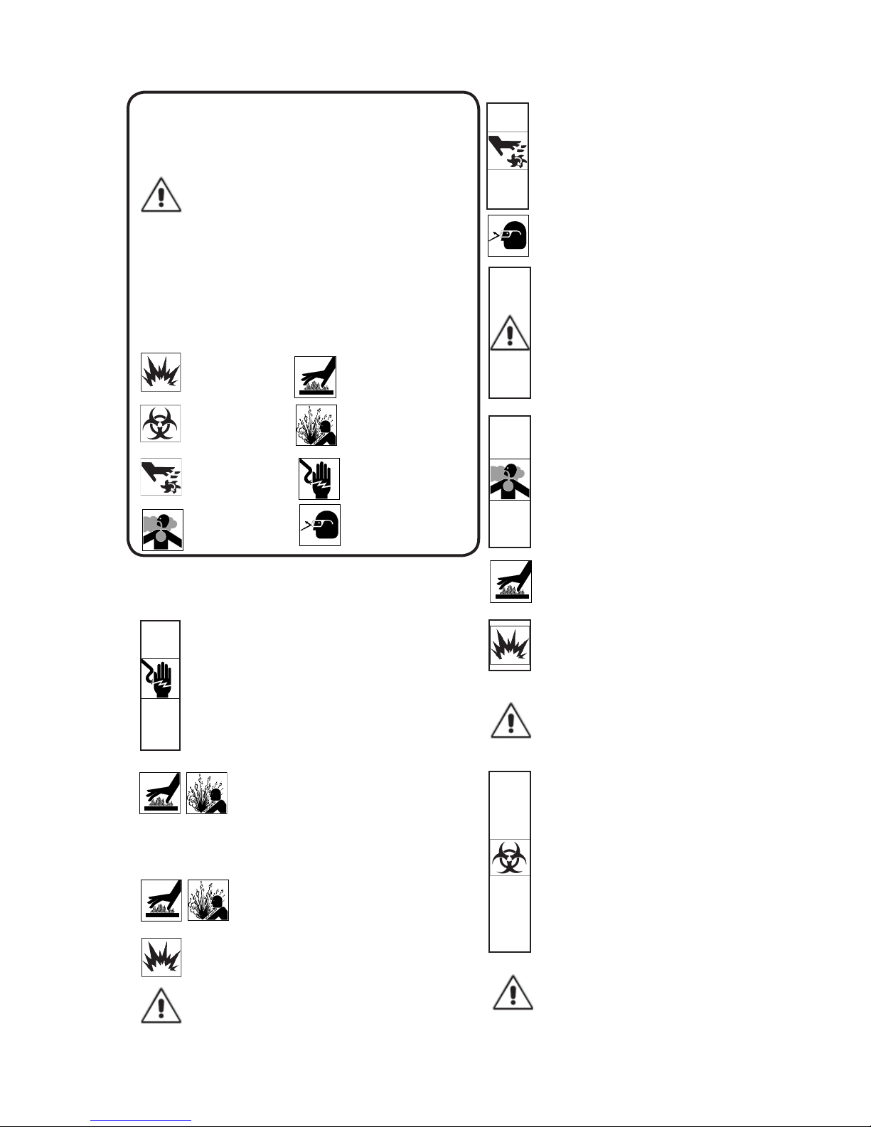
SAFETY FIRST!
Please Read This Before Installing Or Operating Pump.
This information is provided for SAFETY and to PREVENT
EQUIPMENT PROBLEMS. To help recognize this information,
observe the following symbols:
IMPORTANT! Warns about hazards that can result
in personal injury or Indicates factors concerned with
assembly, installation, operation, or maintenance which
could result in damage to the machine or equipment if
ignored.
CAUTION ! Warns about hazards that can or will cause minor
personal injury or property damage if ignored. Used with symbols
below.
WARNING ! Warns about hazards that can or will cause serious
personal injury, death, or major property damage if ignored. Used
with symbols below.
Hazardous fl uids can
cause fi re or explosions,
burnes or death could
result.
Biohazard can cause
serious personal injury.
Rotating machinery
Amputation or severe
laceration can result.
Toxic Fumes Breathing can cause
nausea, fainting or death
Extremely hot - Severe
burnes can occur on contact.
Hazardous fl uids can Hazard-
ous pressure, eruptions or explosions could cause personal
injury or property damage.
Hazardous voltage can
shock, burn or cause death.
Eye protectiong required
WARNING! - DO NOT wear loose clothing that may
become entangled in the impeller or other moving parts.
Always wear appropriate safety gear, such as safety
glasses, when working on the pump or piping.
WARNING! - Keep clear of suction and discharge
openings. DO NOT insert fi ngers in pump with power
connected.
Always wear eye protection when working on pumps.
Make sure lifting handles are securely fastened each
time before lifting. DO NOT operate pump without safety
devices in place. Always replace safety devices that
have been removed during service or repair. Secure the
pump in its operating position so it can not tip over, fall
or slide.
DO NOT exceed manufacturers recommendation for
maximum performance, as this could cause the motor
to overheat.
WARNING! If Engine driven, never operate in an
enclosed building or area where exhaust gases can
accumulate. Never operate near a building where
exhaust gases can seep inside. Never operate in a
pit or sump without making provisions for adequate
ventilation.
WARNING! Do not breathe exhaust fumes when
working in the area of the engine. (Exhaust gases are
odorless and deadly poison.)
Only qualifi ed personnel should install, operate and repair
pump. Any wiring of pumps should be performed by a qualifi ed
electrician.
WARNING ! - To reduce risk of electrical shock, pumps
and control panels must be properly grounded in
accordance with the National Electric Code (NEC) or
the Canadian Electrical Code (CEC) and all applicable
state, province, local codes and ordinances. Improper
grounding voids warranty.
WARNING! - To reduce risk of electrical shock, always
disconnect the pump from the power source before
handling or servicing. Lock out power and tag.
WARNING! Operation against a closed
discharge valve will cause premature bearing
and seal failure on any pump, and on end
suction and self priming pump the heat build
may cause the generation of steam with resulting dangerous
pressures. It is recommended that a high case temperature
switch or pressure relief valve be installed on the pump body.
CAUTION! Pumps build up heat and pressure
during operation-allow time for pumps to cool
before handling or servicing.
WARNING! - DO NOT pump hazardous materials
(fl ammable, caustic, etc.) unless the pump is specifi cally
designed and designated to handle them.
CAUTION! - Do not block or restrict discharge hose, as
discharge hose may whip under pressure.
WARNING! Allow exhaust system to cool before
touching.
Never add fuel to the tank while the engine is running.
Stop engine and allow to cool.
Do not smoke while refueling the engine
Do not refuel near open fl ame
Carefully read instruction manuals supplied by engine
manufacture before attempting to assemble, operate
or service the engine or any part. The “WARNING”
statements indicate potentially hazardous conditions for
operator or equipment.
WARNING! Products Returned Must Be Cleaned,
Sanitized, Or Decontaminated As Necessary Prior
To Shipment, To Insure That Employees Will Not Be
Exposed To Health Hazards In Handling Said Material.
All Applicable Laws And Regulations Shall Apply.
Bronze/brass and bronze/brass fi tted pumps may
contain lead levels higher than considered safe for
potable water systems. Lead is known to cause cancer
and birth defects or other reproductive harm. Various
government agencies have determined that leaded
copper alloys should not be used in potable water
applications. For non-leaded copper alloy materials of
construction, please contact factory.
IMPORTANT! - Crane Pumps & Systems, Inc. is not
responsible for losses, injury, or death resulting from a
failure to observe these safety precautions, misuse or
abuse of pumps or equipment.
3
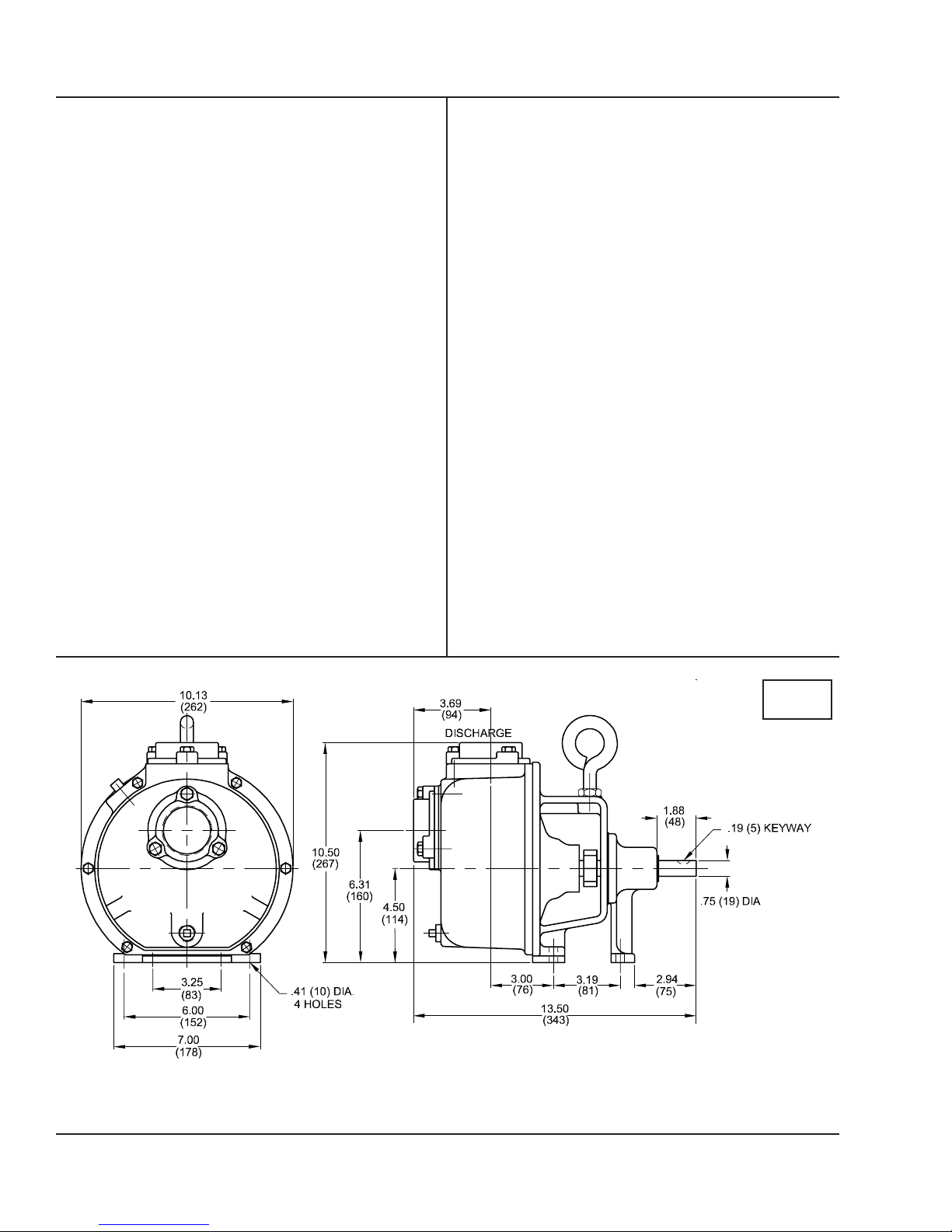
SECTION: A - PUMP SPECIFICATIONS: B4, B6, B9, SB4, SB6, SB9
SUCTION/DISCHARGE:
B4, SB4, B6, SB6 ...............1½” x 1½" NPT, Female
B9, SB9 ...............................2" X 2" NPT Female
LIQUID TEMPERATURE ....160°F (71°C) Continuous
VOLUTE/WEARPLATE ....... B-Cast Iron ASTM A-48, Class 30
SB - 316 Stainless Steel,
Replaceable
CASE...................................B-Cast Iron ASTM A-48, Class 30
SB - 316 Stainless Steel
PEDESTAL ..........................Cast Iron ASTM A-48, Class 30
IMPELLER: Design:
B4 & SB4 ......Open Type, Passes 1/4" Solids
B6 & SB6 .......Open Type, Passes 3/8" Solids
B9 & SB9 .......Open Type, Passes 1/2" Solids
Material .........B-Cast Iron ASTM A-48, Class 30
SB - 316 Stainless Steel
Dynamically Balanced, ISO G6.3
IMPELLER SHAFT ...........Stainless Steel
LOCKING COLLAR ............Stainless Steel. Serves as Shaft
Slinger
SQUARE RINGS ................B - Buna-N
SB - Viton®
HARDWARE .......................B - Corrosion Resistant Steel
SB - Stainless Steel
PAINT .................................B - Air Dry Enamel
SB - Two Part Epoxy
SEAL:B Design ...........Single Mechanical
Lubrication .........Grease, with Self-Feeding Lubricator
Material ..........Rotating Faces - Carbon
Stationary Faces - Ceramic
Elastomer - Buna-N
Hardware - 300 Series Stainless
SB Design ...........Single Mechanical
Lubrication .....Pumped Fluid
Material ..........Rotating Faces - Carbon
Stationary Faces - Ceramic
Elastomer - Viton
Hardware - 300 Series Stainless
BEARING: B4, SB4, B6, SB6
Design ............Single Row, Ball
Lubrication .....Grease
Load ...............Radial & Thrust
BEARING: B9, SB9
Design ............Double Row, Ball
Lubrication .....Grease
Load ...............Radial & Thrust
CHECK VALVE:
Material .........B - Valve Flap-Neoprene
SB - Valve Flap - Viton
Weight-Cast Iron ASTM A-48,
Class 30
OPTIONAL EQUIPMENT ....Seal Material, Case Heater,
Stainless Hardware; High Temperature Control; Flex Coupled
Assy., with Base & OSHA Guard; Right Hand V-Belt Drive
Assy., Left Hand V-Belt Drive Assy., and In-Line Vertical V-
Belt Drive Assy., with Base, Motor Adjusting Base & OSHA
Guard.
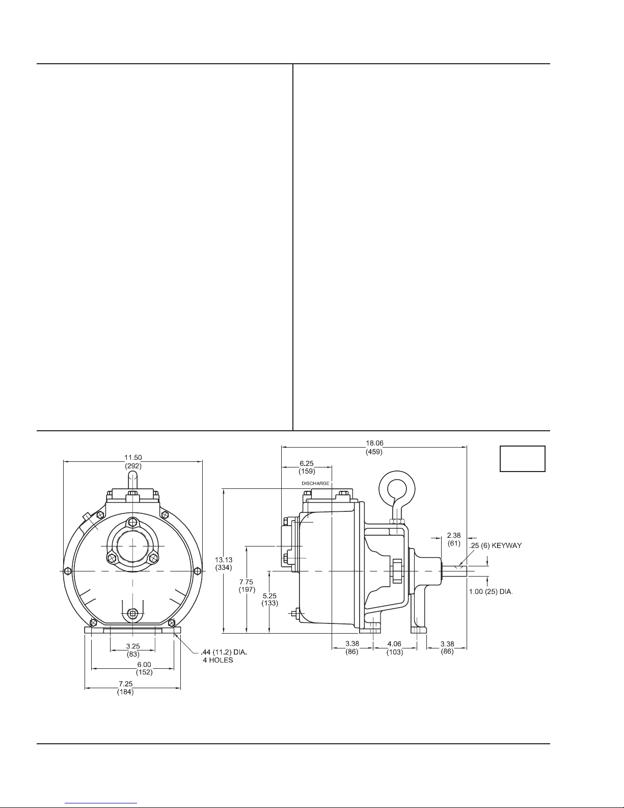
inches
(mm)
IMPORTANT !
1.) DO NOT USE FOR PUMPING FLUIDS WITH A FLASH POINT OF LESS THAN 100°F.
2.) MAKE CERTAIN THAT PUMP AND/OR MOTOR ASSEMBLY AND CONTROLS HAVE THE APPROPRIATE RATINGS FOR THE GIVEN APPLICATION
AREA CLASSIFICATION. (ie DIVISION I, AGENCY LISTING ETC.)
4
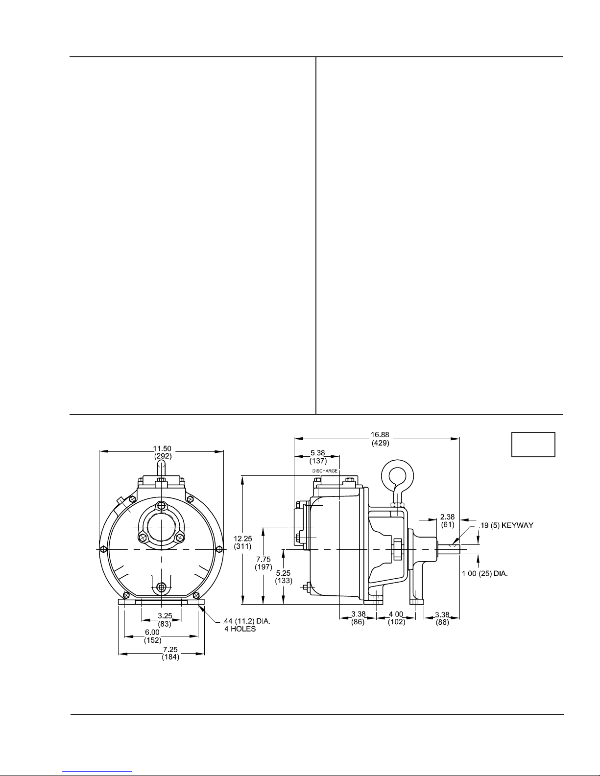
SECTION: A - PUMP SPECIFICATIONS: B12, SB12, BH7, SBH7
SUCTION/DISCHARGE ........... 2" X 2" NPT Female
LIQUID TEMPERATURE ......... 160°F (71°C) Continuous
VOLUTE/WEARPLATE
B & BH ......................... Cast Iron ASTM A-48, Class 30
SB & SBH .........................316 Stainless Steel, Replaceable
CASE B & B H ......................... Cast Iron ASTM A-48, Class 30
SB & SBH ................... 316 Stainless Steel
PEDESTAL ......................... Cast Iron ASTM A-48, Class 30
IMPELLER:
Design B12 & SB12 ... Open Type, Passes 1/2" Solids
Design BH7 & SBH7 ... Open Type, Passes 1/4" Solids
Material B & BH ...........Cast Iron ASTM A-48, Class 30
SB & SBH ..... 316 Stainless Steel
Dynamically Balanced,
ISO G6.3
IMPELLER SHAFT ................ Stainless Steel
LOCKING COLLAR ................. Stainless Steel. Serves as
Shaft Slinger
SQUARE RINGS ..................... B & BH - Buna-N
SB & SBH - Viton®
HARDWARE
B & BH ...................... Corrosion Resistant Steel
SB & SBH ................... Stainless Steel
PAINT B & BH ...................... Air Dry Enamel
SB & SBH ................... Two Part Epoxy
SEAL:
B & BH Design ...................... Single Mechanical
Lubrication ...................Grease, with Self-Feeding
Lubricator
Material ...................... Rotating Faces - Carbon
Stationary Faces - Ceramic
Elastomer - Buna-N
Hardware - 300 Series Stainless
SB & SBH
Design ...................... Single Mechanical
Lubrication ...................Pumped Fluid
Material ...................... Rotating Faces - Carbon
Stationary Faces - Ceramic
Elastomer - Viton
Hardware - 300 Series Stainless
BEARING:
Design ...................... Single Row, Ball
Lubrication ...................Grease
Load ...................... Radial & Thrust
CHECK VALVE:
Material ...................... B & BH - Valve Flap
Neoprene
SB & SBH - Valve Flap
Viton
Weight-Cast Iron ASTM A-48,
Class 30
OPTIONAL EQUIPMENT ......... Seal Material, Case Heater,
Stainless Hardware; High Temperature Control; Flex Coupled
Assy., with Base & OSHA Guard; Right Hand V-Belt Drive
Assy., Left Hand V-Belt Drive Assy., and In-Line Vertical
V-Belt Drive Assy., with Base, Motor Adjusting Base & OSHA
Guard.
inches
(mm)
IMPORTANT !
1.) DO NOT USE FOR PUMPING FLUIDS WITH A FLASH POINT OF LESS THAN 100°F.
2.) MAKE CERTAIN THAT PUMP AND/OR MOTOR ASSEMBLY AND CONTROLS HAVE THE APPROPRIATE RATINGS FOR THE GIVEN APPLICATION
AREA CLASSIFICATION. (ie DIVISION I, AGENCY LISTING ETC.)
5
SECTION: A - PUMP SPECIFICATIONS: B19, SB19, B21, SB21
SUCTION/DISCHARGE .........3" X 3" NPT Female
LIQUID TEMPERATURE .......160°F (71°C) Continuous
VOLUTE/WEARPLATE
B .......................Cast Iron ASTM A-48, Class 30
SB .....................316 Stainless Steel,
Replaceable
CASE B .......................Cast Iron ASTM A-48, Class 30
SB .....................316 Stainless Steel
PEDESTAL .............................Cast Iron ASTM A-48, Class 30
IMPELLER: Design ...............Open Type, Passes 3/4" Solids
Material
B .......................Cast Iron ASTM A-48, Class 30
SB .....................316 Stainless Steel
Dynamically Balanced, ISO G6.3
IMPELLER SHAFT ..............Stainless Steel
LOCKING COLLAR ..............Stainless Steel. Serves as
Shaft Slinger
SQUARE RINGS ...................B - Buna-N
SB - Viton®
HARDWARE ..........................B - Corrosion Resistant Steel
SB - Stainless Steel
PAINT ....................................B - Air Dry Enamel
SB - Two Part Epoxy
SEAL: B Design ..............Single Mechanical
Lubrication ........Grease, with Self-Feeding
Lubricator
Material .............Rotating Faces - Carbon
Stationary Faces - Ceramic
Elastomer - Buna-N
Hardware - 300 Series Stainless
SB Design ..............Single Mechanical
Lubrication ........Pumped Fluid
Material .............Rotating Faces - Carbon
Stationary Faces - Ceramic
Elastomer - Viton
Hardware - 300 Series Stainless
BEARING:
B19 & SB19 Design ..............Double Row, Ball
B21 & SB21 Design ..............Single Row, Ball
Lubrication ........Grease
Load ..............Radial & Thrust
CHECK VALVE:
Material ............B - Valve Flap-Neoprene
SB - Valve Flap - Viton
Weight-Cast Iron ASTM A-48,
Class 30
OPTIONAL EQUIPMENT .......Seal Material, Case Heater,
Stainless Hardware; High Temperature Control; Flex Coupled
Assy., with Base & OSHA Guard; Right Hand V-Belt Drive
Assy., Left Hand V-Belt Drive Assy., and In-Line Vertical V-
Belt Drive Assy., with Base, Motor Adjusting Base & OSHA
Guard.
inches
(mm)
IMPORTANT !
1.) DO NOT USE FOR PUMPING FLUIDS WITH A FLASH POINT OF LESS THAN 100°F.
2.) MAKE CERTAIN THAT PUMP AND/OR MOTOR ASSEMBLY AND CONTROLS HAVE THE APPROPRIATE RATINGS FOR THE GIVEN APPLICATION
AREA CLASSIFICATION. (ie DIVISION I, AGENCY LISTING ETC.)
6

SECTION B: GENERAL INFORMATION
B-1) To the Purchaser:
Congratulations! You are the owner of one of the fi nest
pumps on the market today. Crown® Pumps are products
engineered and manufactured of high quality components.
Over one hundred years of pump building experience along
with a continuing quality assurance program combine to
produce a pump which will stand up to the toughest pumping
projects.
This pump manual will provide helpful information concerning
installation, maintenance, and proper service guidelines.
Locate the pump on a fi rm footing to make sure the pump
will not move due to vibration. Flex coupled and V-belt
driven units should be permanently grouted onto a cement
foundation. The pumps should be level to provide favorable
operating conditions. In addition, the fl exible coupling should
be realigned after grouting in order to eliminate excessive
wear on the coupling.
Allow a minimum of 18 inches in front of the pump case cover
or hatch cover to permit easy removal and access to the
interior of the pump. On belt driven units, allow a minimum
of 10 inches at the shaft end to permit easy removal of the
pedastal or rotating cartridge.
B-2) Receiving:
Upon receiving the pump, it should be inspected for
damage or shortages. If damage has occurred, fi le a claim
immediately with the company that delivered the pump. If the
manual is removed from the crating, do not lose or misplace.
B-3) Storage:
Short Term - Crown Pumps are manufactured for effi cient
performance following long inoperative periods in storage.
For best results, pumps can be retained in storage, as factory
assembled, in a dry atmosphere with constant temperatures
for up to six (6) months.
Long Term - Any length of time exceeding six (6) months, but
not more than twenty four (24) months. The units should be
stored in a temperature controlled area, a roofed over walled
enclosure that provides protection from the elements (rain,
snow, wind blown dust, etc.), and whose temperature can be
maintained between +40 deg. F and +120 deg. F.
If extended high humidity is expected to be a problem, all
exposed parts should be inspected before storage and all
surfaces that have the paint scratched, damaged, or worn
should be recoated with a water base, air dry enamel paint.
All surfaces should then be sprayed with a rust-inhibiting oil.
B-4) Service Centers:
For the location of the nearest Crown Service Center, check
your representative or Crane Pumps & Systems, Inc., in
Piqua, Ohio, telephone (937) 778-8947 or Crane Pumps &
Systems Canada, Bramton, Ontario, (905) 457-6223.
C-2) Suction:
It is advisable to use a suction line of the same size as the
pump port size. All horizontal suction lines should slope up to
the pump to avoid trapped air pockets. An adjustable stand,
pipe clamp or fl oor fl ange must be installed to support the
weight of the suction line. On suction lifts less than 5 feet, it is
sometimes possible to increase capacity slightly by oversizing
the suction line, but oversized suction pipe on high suction
lifts will create priming problems. Using a smaller suction line
than the pump port size can cause internal damage to the
pump.
The suction line must not have holes, even small holes. The
smallest air leak in the suction line may prevent the pump
from priming. Coat all threaded connections in the suction
line with pipe thread compound to insure an air tight joint. In
addition, suction fl anges should be pulled up tight to prevent
air leaks. Where fi ber gaskets are used, coat them with
grease.
Use a strainer on suction line to prevent the entrance of
oversize solids. This strainer should be submerged deep
enough to prevent air from being drawn into the suction line,
thus reducing the pump’s capacity and pressure.
CAUTION! - This pump should not be operated
without a strainer on the end of the suction line
to prevent sticks, stones, rags and other foreign
matter from being drawn into the impeller. The
strainer should be cleaned regularly to insure full
fl ow.
SECTION C: INSTALLATION RECOMMENDATIONS:
C-1) Location:
Locate the pump as close to the source of supply as possible.
Although the pump will operate on suction lifts of 25 feet, it is
desirable to keep the suction lift less than 15 feet, if possible.
The closer the pump can be located to the source of supply,
the faster the pump will prime and a greater capacity can be
pumped.
All pump units rotate clockwise when looking from the motor
end (driven end) of the pump. Also, rotation arrows are
located on the pump. On three phase units with threaded
suction/discharge connections the impellers are threaded on
the shaft and it is necessary to slide one half of the fl exible
coupling back when checking rotation in order to eliminate
the possibility of unscrewing the impeller and damaging the
pump. NOTE: Where impellers thread on pump shaft, never
check the direction of electric motor rotation without fi rst
disconnecting fl exible coupling.
C-3) Discharge:
Connect discharge hose or pipe to discharge on pump.
If Discharge hose is used, protect it from being driven over.
Do not use quick closing check valves.
SECTION D: OPERATION RECOMMENDATIONS:
1. Fill the pump case with liquid prior to starting the pump. A
self priming pump does require the case to be at least 2/3 full
of liquid in order to self prime. Operate at suffi cient speed to
prime pump. Generally speaking, the pump will prime faster if
it is operated at a fast speed.
2. Place the self-feeding grease lubricator in operation by
turning the wing nut on the threaded plunger shaft counter
clockwise as far as it will go. Do not force the plunger into the
grease cup as this can cause a seal failure. See Maintenance
Recommedations, Paragraphs 1 and 2 for instructions on
fi lling the grease cup.
7
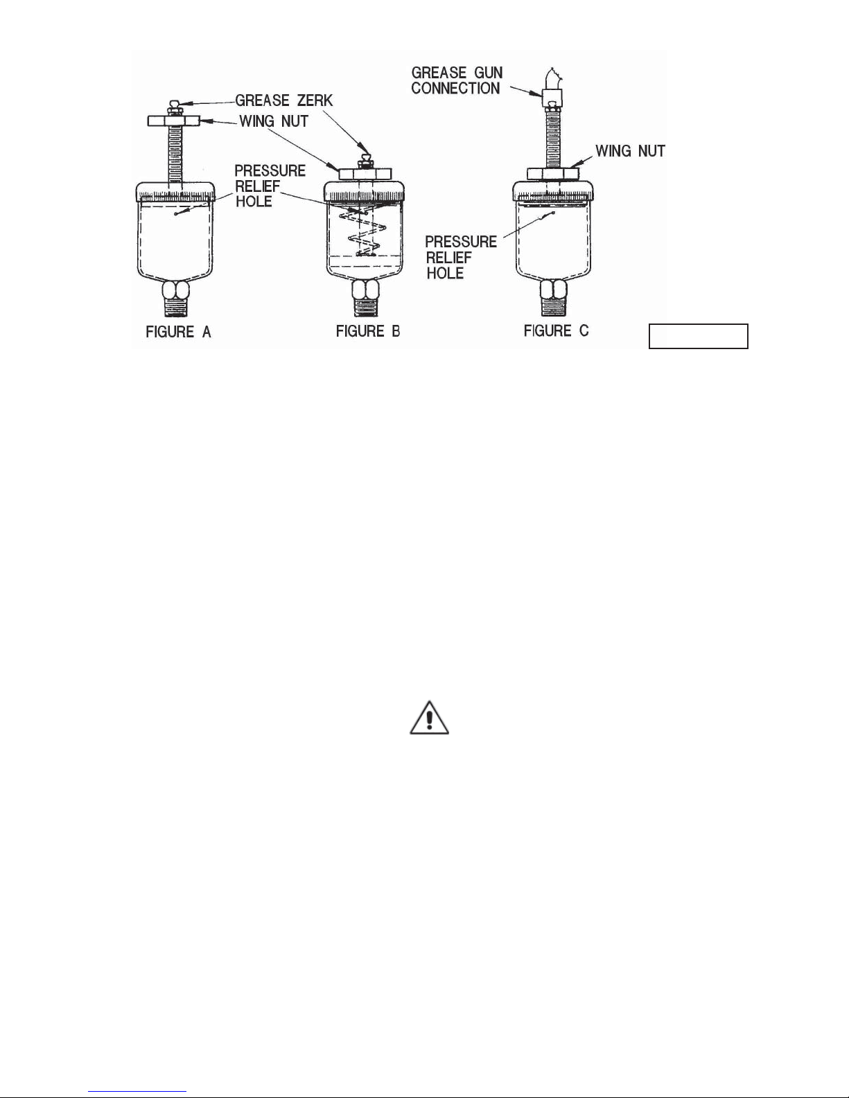
FIGURE 1
3. In cold weather operation, the pump will not freeze as
long as it is running. However, it may freeze if it is not drained
while standing idle. To drain the pump, remove the drain plug
at the bottom of the pump case and rotate the impeller at
least once to assure removal of all the water.
4. The discharge of a self priming centrifugal pump may be
closed briefl y without damaging the pump. However, the wa-
ter will soon heat up and this can damage to the pump seal.
5. It is not desirable to run the pump without liquid in the
pump case. If the pump must be run in order to check the
operation of the engine or motor, fi ll the case with suffi cient
water to keep the rotating seal wet. This will eliminate damage to the seal and other pump parts.
6. If the pump has been idle for some time, the impeller may
appear to be stuck or locked in place. This is usually caused
by a fi lm of rust or dirt between the impeller and volute. A little
extra force on the crank may break it loose. If not, the pump
must be dismantled.
SECTION E: MAINTENANCE RECOMMENDATIONS:
E-1) Seal Lubrication:
A self-feeding lubricator is provided to supply grease to the
shaft seal of the pump. The grease cup is empty when the
wing nut, positioned at the outer end of the threaded plunger
shaft, recedes to the cap of the grease cup. To refi ll the
grease cup, rotate the wing nut clockwise as far as it will
go, attach a zerk gun to the zerk fi tting, then fi ll until grease
oozes from the relief hole on the side of the cup. For operation, return the wing nut to the end of the plunger. Never
force the plunger into the grease cup as this can cause seal
failures. (See Fig. 1)
A #1 grease is normally recommended. However, where high
ambient temperatures are encountered, such as in direct
sunlight, a #2 grease can be used. Use a water resistant,
nonfi berous grease. Lithium base greases are excellent and
molydisulphide is acceptable. Normally, the sodium soap
base greases are the only non-water resistant types that are
not acceptable for mechanical seal lubrication.
If the pump is inoperative for a long period of time, or appears
not to use any grease, remove and clean the cup thoroughly.
Caked grease in the cup can create a problem of
non-lubrication to the seal. Under normal conditions, a grease
cup full of grease will last three to four months. If a grease
seal requires grease every day, and it is not leaking past the
outer lip seal it indicates that the seal is wearing out. The
internal pressure of the pump will often force the cup plunger
out when the seal leaks badly.
E-2) Shaft Seal Replacement:
All parts of the pump are easily dismantled by simply
removing nuts and screws. Rotating parts of the shaft seal
grip the shaft by friction and may be frozen to the shaft
through long usage.
If the mechanical shaft seal is not leaking and it is necessary
to dismantle part of the pump for inspection or cleaning DO
NOT disturb the shaft seal other than its spring if the impeller
is removed. Once a shaft seal has been in operation it cannot
be removed and replaced without leaking.
CAUTION ! - Handle parts with extreme care.
Do not scratch or mar lapped surfaces.
It is recommended to remove the pump side from the support
bracket. After the pump has been disassembled make sure
that the shaft and seat areas in the pump side are as clean
as possible. The shaft must not be sharp, but neatly rounded
and polished to a 1/32” radius. This radius and the shaft, on
which the rubber bellows grips, must be polished with 180 to
240 grit emery cloth. The seal will install relatively easy if the
shaft is properly polished.
Install the seat assembly (1 and 2 or 1A and 2A, see Figure
2) in pump side adapter (12) using SAE# 10 oil on the rubber
parts. They may install easier by fi rst inserting the rubber part
and then sliding the seat part into the rubber. All of this must
be done with the fi ngers only .
8

FIGURE 2
1 - Ni-Resist Stationary Seat
1A - Ceramic Stationary Seat
2 - Buna-N Seat Ring
2A - Buna-N Seat Cup
3 - Stainless Retainer
4 - Stainless Drive Band
5 - Stainless Spring
6 - Stainless Springholder
7 - Cran-Carb® Mating Ring
7A - Carbon Mating Ring
8 - Buna-N Bellows
Cross SEction of SEals.
Two Styles Shown
Now assemble the spring and rotating portion of the seal
onto the impeller shaft (19). Lubricate the impeller shaft (19)
and the inside of the bellows each with 2 or 3 drops of SAE#
10 oil. Install this assembly into adapter (12), this may take
several minutes, therefore, oscillate the seal back and forth
on the shaft to make sure it does not stick to the shaft until
gage pin is in place and the clamp tightened.
If for any reason the gage pin does not give proper clearance,
quickly adjust the impeller clearance before the rubber
bellows seats on the shaft.
E-3) Impeller:
These pumps have their impellers threaded on with right
hand threads.
The clearance between an open faced impeller and its wear
surface in the volute is set at the factory at approximately
.015 inches. This clearance is re-adjustable by relocating
the shaft at the clamping arrangement. In cases where
much sand is being pumped, close clearances may bind
the impeller and volute and overload the motor. It may be
necessary to provide extra clearance on these.
When reassembling a dismantled pump, clean all parts and
especially areas where gaskets and o-rings are located.
Grease all gaskets and o-rings and areas where o-rings must
slide when assembling.
FIGURE 3
9

TROUBLE SHOOTING
CAUTION ! Always disconnect the pump from the electrical power source before handling.
If the system fails to operate properly, carefully read instructions and perform maintenance recommendations.
SYMPTOM POSSIBLE CAUSE(S) CHECK
1. Air leak in suction side of system. a. Threaded joints in suction line for tight fi t
2. Air bleed line blocked, or Air bleed valve
A. Pump not primed - Vacuum
gauge reading less than normal
B. Pump not priming - Vacuum
gauge reads more than normal 1. Suction side of system clogged
C. Pump primes - Vacuum gauge
reads normal, discharge gauge
reads lower than normal
D. Pump primes - Vacuum gauge
reads near normal, Discharge
gauge reads higher than normal
E. Pump looses prime when shut
off - Vacuum gauge recedes to
zero
closed.
3. Insuffi cient liquid in case
4. Operating speed to low
5. Plugged pump
6. Mechanical defects
1. Small air leak in suction side of system
2. Pump speed too slow
3. Mechanical defects
1. Plugged discharge
1. Check valve leaking
b. Gasket in suction line for tight fi t
c. O-rings in case cover for nicks or cuts
d. Mechanical seal for air leaks
e. Bottom drain plug for air leaks
f. O-rings in pump side for nicks or cuts
g. Vacuum gauge may be leaking internally
a. Check line or valve
a. Pump case for water level
b. Suction check valve for obstructions or deterioration
a. Belts for proper tension
b. Motor for low voltage
a. Impeller for lodge foreign material
b. Vent line for stoppage
a. Impeller - volute for proper clearance
b. Impeller and volute for damage
c. Pump for worn parts
a. End of suction line for obstructions
b. Suction pipe for obstructions
c. Suction check valve for obstructions
a. For excessive air in discharge line
b. Refer to A-1, a through g
a. Belts for proper tension
b. Motor for low voltage
a. Impeller - volute for proper clearance
b. Impeller and volute for damage
c. Pump for worn parts
a. Discharge line for obstructions
b. Discharge valves to insure proper operation
a. Check valve for obstructions or deterioration
b. Leak in suction pipe threads or fl anges
c. Water level bubbler control line too close to suction pipe
d. The infl uent liquid for chuming air into the sump and
entering the suction pipe
10
 Loading...