

Page 1
SERIES
Discount-Equipment.com
BULLETIN No.
SUPERSEDES
DATE
MM ~ Mech.
200078-R04
200078-R03
May 2004
MORTAR MIXER MODELS:
4S, S4S, 5S, 6S, 6SR, S6SR, 6PR,
8S, S8S, 8P, 10S, S10S, 12S & S12S
OPERATOR'S MANUAL
www.discount-equipment.com
Page 2

Discount-Equipment.com is your online resource for commercial and industrial
Discount-Equipment.com
quality parts and equipment sales.
Locations:
Florida (West Palm Beach): 561-964-4949
Outside Florida TOLL FREE: 877-690-3101
Need parts? Check out our website at www.discount-equipment.com
Can’t find what you need?
Click on this link: http://www.discount-equipment.com/category/5443-parts/ and fill out
the request form.
Please have the machine model and serial number available in order to help us get
you the correct parts. One of our experienced staff members will get back to you with
a quote for the right part that your machine needs.
We sell worldwide for the brands: Genie, Terex, JLG, MultiQuip, Mayco, Toro/Stone,
Diamond Products, Magnum, Airman, Mustang, Power Blanket, Nifty Lift, Atlas Copco,
Chicago Pneumatic,
Tsurumi, Husquvarna/Target, Whiteman-Concrete/Mortar, Stow-Concrete/Mortar, Baldor,
Wacker, Sakai, Snorkel, Upright, Mi-T-M, Sullair, Neal, Basic, Dynapac, MBW, Weber,
Bartell, Bennar Newman, Haulotte, Ditch Runner, Blaw-Knox, Himoinsa, Best, Buddy,
Crown, Edco, Wyco, Bomag, Laymor, Terremite, Barreto, EZ Trench, Takeuchi, Basic, Bil-
Jax, Curtis, Gehl, Heli, Honda, ICS/PowerGrit, Puckett,
Clipper, MMD, Koshin, Rice, Gorman Rupp, CH&E, Cat Pumps, Comet, General Pump,
Giant,AMida, Coleman, NAC, Gradall, Square Shooter, Kent, Stanley, Tamco, Toku, Hatz,
Kohler, Robin, Wisconsin, Northrock, Oztec, Toker TK, Rol-Air, Small Line, Wanco, Yanmar
Allmand Brothers, Essick, Miller Spreader, Skyjack, Lull, Skytrak,
Waldon, ASV, IHI, Partner, Imer,
Page 3

TABLE OF CONTENTS
Discount-Equipment.com
SECTION DESCRIPTION
Proposition 65 ................................................................................ i
1 Introduction .........................................................................................1
2 Safety ...............................................................................................2
2.1 General Safety ..............................................................................3
2.2 Operating Safety .........................................................................4
2.3 Maintenance Safety ...................................................................5
2.4 Transport Safety ..........................................................................5
2.5 Tire Safety ......................................................................................5
2.6 Storage Safety ..............................................................................5
2.7 Refueling Safety ..........................................................................6
2.8 Electrical Safety ...........................................................................6
2.9 Safety Signs ...................................................................................6
2.10 Sign-O Form ...............................................................................7
3 Safety Sign Locations ................................................................8
4 Operation .................................................................................... 13
4.1 To the New Operator or Owner .......................................... 13
4.2 How The Machine Works ....................................................... 14
4.3 Pre-Operation Checklist ........................................................15
4.4 Pre-Start Procedures ............................................................... 15
4.5 Machine Break-In ..................................................................... 16
4.6 Controls ....................................................................................... 17
4.7 Operating ................................................................................... 19
4.8 Transporting .............................................................................. 28
4.9 Storage ........................................................................................31
5 Service and Maintenance ..................................................... 32
5.1 Service ......................................................................................... 32
5.1.1 Fluids and Lubricants ...................................................................................32
5.1.2 Greasing ............................................................................................................32
5.1.3 Servicing Intervals ......................................................................................... 33
5.1.4 Service Record ................................................................................................38
5.2 Maintenance .............................................................................. 39
5.2.1 Engine Oil Changing ..................................................................................... 39
5.2.2 Engine Speed Setting ...................................................................................40
5.2.3 Air Cleaner Maintenance ............................................................................. 41
5.2.4 Belt Tension and Alignment ....................................................................... 42
5.2.5 Wiper Spacing and Replacement ............................................................. 43
5.2.6 Gearbox Oil Changing .................................................................................. 44
6 Trouble Shooting ..................................................................... 45
7 Specications ............................................................................ 46
7.1 Mechanical ................................................................................. 46
7.2 Bolt Torque ................................................................................. 47
8 Index ............................................................................................. 48
i
Page 4
WARNING
Discount-Equipment.com
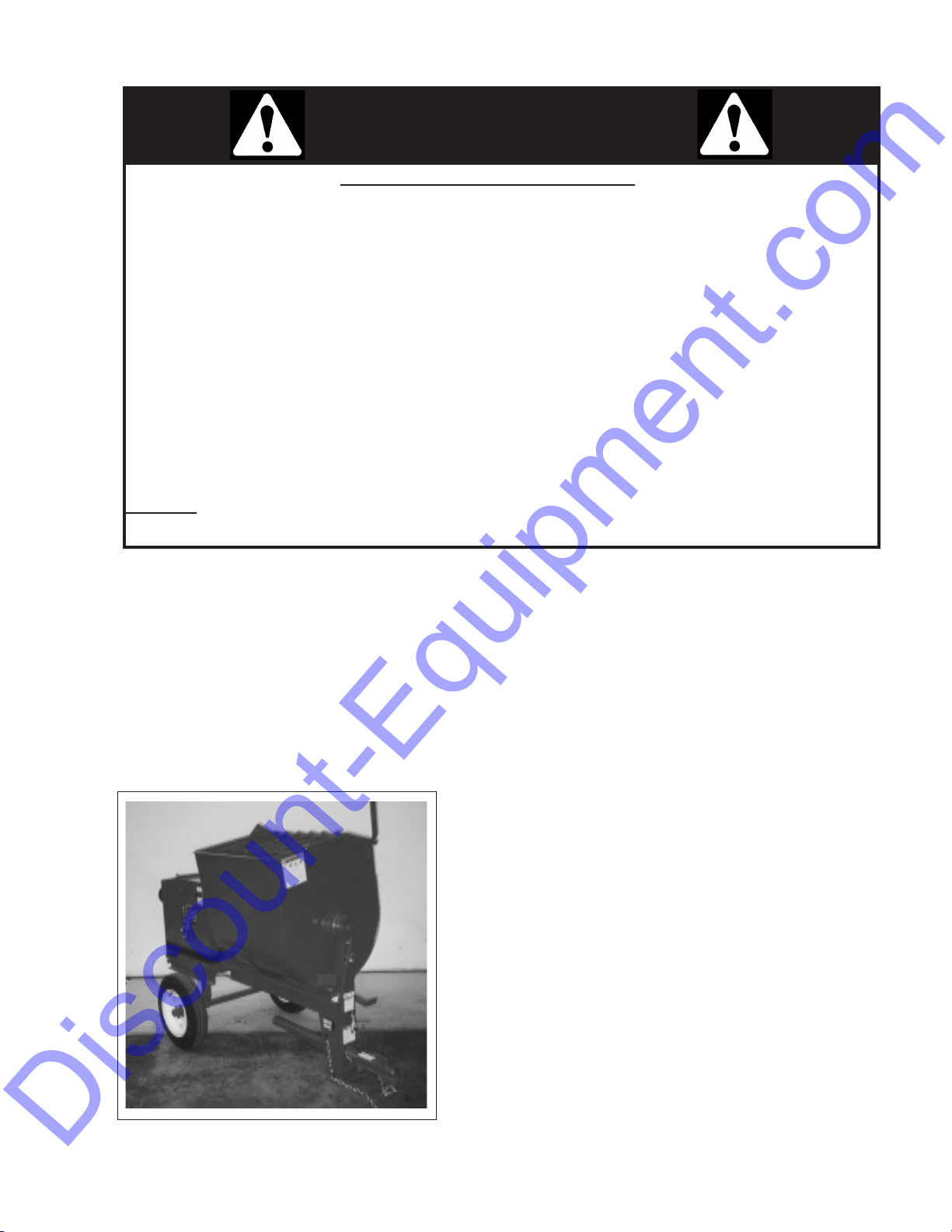
CALIFORNIA - Proposition 65 Warning
Engine exhaust and some of its constituents and some dust created by power sanding, sawing,
grinding, drilling and other construction activities contains chemicals known to the State of California
to cause cancer, birth defects and other reproductive harm.
Some examples of these chemicals are:-
Lead from lead-based paints
Crystalline silica from bricks
Cement and other masonry products
Arsenic and chromium from chemically
treated lumber
Your risk from these exposures varies, depending on how often you do this type of work. To reduce
your exposure to these chemicals:
ALWAYS work in a well ventilated area, and work with approved safety equipment, such as dust
masks that are specially designed to lter out microscopic particles.
1 INTRODUCTION
Congratulations on your choice of a Crown Construction Equipment Mortar Mixer to complement your construction
operation. This equipment has been designed and manufactured to meet the needs of a discriminating buyer for the
ecient mixing of mortar or plaster.
Safe, ecient and trouble free operation of your Crown Mortar Mixer requires that you and anyone else who will be
operating or maintaining the Mixer, read and understand the Safety, Operation, Maintenance and Trouble Shooting
information contained in the Operator's Manual.
This manual is applicable to all the Model 4S, 5S, S5S, 6S, 6SR,
S6SR, 6PR, S8S, 8S, 8P, 10S, S10S,12S and S12S Mortar Mixers built
by Crown Construction Equipment. Use the Table of Contents or
Index as a guide when searching for specic information.
Keep this manual handy for frequent reference and to pass on to
new operators or owners. Call your Crown Construction Equipment distributor or dealer if you need assistance or information.
OPERATOR ORIENTATION - The directions left, right, front and rear,
as mentioned throughout this manual, are as seen from behind
the machine and facing in the direction of towing.
Page 5

2 SAFETY
Discount-Equipment.com
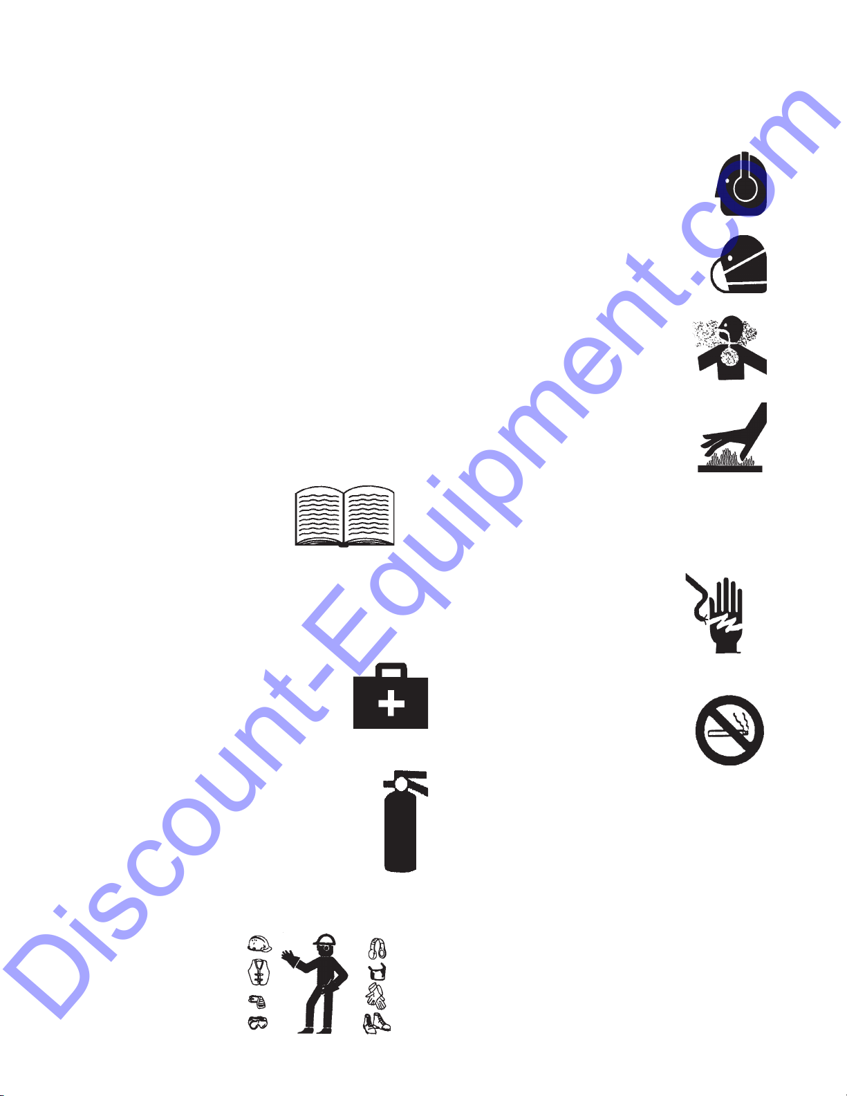
SAFETY ALERT SYMBOL
This Safety Alert symbol means
ATTENTION! BECOME ALERT! YOUR
SAFETY IS INVOLVED!
3 Big Reasons
SIGNAL WORDS:
Note the use of the signal words DANGER,
WARNING and CAUTION with the safety
messages. The appropriate signal word for
each message has been selected using the
following guide-lines:
Why is SAFETY important to you?
Accidents Disable and Kill
Accidents Cost
Accidents Can Be Avoided
DANGER - Indicates an imminently hazardous situ-
ation that, if not avoided, will result in
death or serious injury. This signal word
is to be limited to the most extreme situations, typically for machine components
that, for functional purposes, cannot be
guarded.
WARNING -
Indicates a potentially hazardous situ-
ation that, if not avoided, could result
in death or serious injury, and includes
hazards that are exposed when guards
are removed. It may also be used to alert
against unsafe practices.
The Safety Alert symbol identies important safety messages on the Crown
Mortar Mixer and in the manual. When
you see this symbol, be alert to the
possibility of personal injury or death.
Follow the instructions in the safety
message.
Indicates a potentially hazardous situ-
CAUTION -
ation that, if not avoided, may result in
minor or moderate injury. It may also be
used to alert against unsafe practices.
SAFETY
YOU are responsible for the SAFE operation and maintenance of your Concrete Mixer. YOU must ensure that you
and anyone else who is going to operate, maintain or work
around the Concrete Mixer be familiar with the operating
and maintenance procedures and related SAFETY information contained in this manual. This manual will take you stepby-step through your working day and alerts you to all good
safety practices that should be adhered to while operating
the Mixer.
Remember, YOU are the key to safety. Good safety
practices not only protect you but also the people
around you. Make these practices a working part
of your safety program. Be certain that EVERYONE
operating this equipment is familiar with the recommended operating and maintenance procedures and
follows all the safety precautions. Most accidents can
be prevented. Do not risk injury or death by ignoring
good safety practices.
1
Page 6
• Mixerownersmustgiveoperatinginstructions
Discount-Equipment.com
to operators or employees before allowing them
to operate the machine, and at least annually
thereafter.
Stop engine, disconnect spark plug wire and
7.
wait for all moving parts to stop before servicing,
adjusting, repairing or cleaning.
• Themostimportantsafetydeviceonthisequipment is a SAFE operator. It is the operator’s
responsibility to read and understand ALL Safety
and Operating instructions in the manual and to
follow these. All accidents can be avoided.
• Apersonwhohasnotreadandunderstoodall
operating and safety instructions is not qualied
to operate the machine. An untrained operator
exposes himself and bystanders to possible serious injury or death.
• Donotmodifytheequipmentinanyway.
Unauthorized modication may impair the
function and/or safety and could aect the life
of the equipment.
2.1 GENERAL SAFETY
1. Read and understand the
Operator's manual and all
safety signs before
operating, maintaining,
adjusting, servicing or
cleaning the Mixer.
2.
Only trained competent persons shall operate the
Mixer. An untrained operator is not qualied to
operate the machine.
3.
Have a rst-aid kit available for use,
should the need arise and know how
to use it.
4.
Do not allow riders when towing.
5.
Have a re extinguisher available for use
should the need arise and know how to use
it.
Wear appropriate hearing protection when
8.
operating for long periods of time.
Dust Hazard ~ Wear appropriate dust
mask around this equipment.
9.
Ventilation ~ Never operate any
gas powered equipment in a poorly
10.
ventilated or enclose area. Avoid
prolonged breathing of exhaust
gases.
Hot Surface ~ Avoid contact with hot
exhaust system and engine.
11.
Allow to cool before performing
repairs or service.
2.1 GENERAL SAFETY
Electrocution Hazard ~ Always
12.
use proper size grounded
extension cord. Inspect all
extension cords for cuts, frayed
wire and broken connectors.
Do not use cords if not in good
condition.
13. Do not refuel the machine while
smoking or when
near open ame or sparks.
2.2 OPERATING SAFETY
1. Read and understand the Operator’s Manual and all
safety signs before operating, servicing, adjusting, or
cleaning the Mixer.
6.
Wear appropriate protective gear. This list
includes, but is not limited to:
- A hard hat
- Protective boots
with
slip resistant soles
- Protective goggles
- Heavy gloves
- Hearing protection
2. Do not allow riders on the machine during transport.
3. Install, close and secure all guards, shields and hoods
before starting or operating.
4. Stop engine or motor, disconnect spark plug wire or
unplug power cord, and wait for all moving parts to
stop before servicing, adjusting, repairing, or cleaning.
2
Page 7

5. Clear the area of all bystanders before starting.
Discount-Equipment.com
6. Keep hands, feet, hair and clothing away from
moving parts.
7. Keep working area clean and dry to prevent slipping and tripping.
8. Do not run the mixer in an explosive atmosphere
or in a poorly ventilated or enclosed area.
3. Follow good shop practices
- Keep service area
clean and dry.
- Be sure electrical
outlets and tools
are properly
grounded.
- Use adequate
light for the job
at
9. Wear appropriate hearing protection when operating for long periods of time.
10. Always attach safety chain when towing.
11. Do not exceed a safe travel speed when towing.
Slow down for corners and when going over
rough terrain.
12. Review safety instructions with all operators annually.
Gas engine powered units:
• Do not place hands in the drum unless the
engine is OFF and the spark plug wire is disconnected.
• Stay away from hot engine components during
operation.
• Do not smoke when refueling gas engine.
Electric motor powered units:
4. Keep hands, feet, clothing and hair away from all
moving and/or rotating parts.
5. Do not place hands in the drum unless the
engine is o and the spark plug wire is disconnected or the power cord is unplugged.
6. Do not attempt any adjustment or maintenance
to any system of the Mixer unless the power
source is disabled.
7. Make sure that all guards, shields and hoods are
properly installed and secured before operating
the Mixer.
8. Securely support the machine using blocks
or safety stands before working beneath it or
changing tires.
9. Store and transfer gasoline, solvents, cleaners
or any ammable liquids only in safety standard
approved containers.
2.4 TRANSPORT SAFETY
• Do not place hands in the drum unless the motor is
OFF and the power cord unplugged.
• Have a licensed electrician wire up and provide
power to the motor.
• Only use a power cord that is grounded.
• Always use an electrical cord with the required
power carrying capacity.
2.3 MAINTENANCE SAFETY
1. Review the Operator's Manual and all safety
items before working with, maintaining or operating the Mixer.
2. Stop engine or motor, disconnect spark plug wire
or unplug power cord, and wait for all moving
parts to stop before servicing, adjusting, repairing, or cleaning.
1. Read and understand ALL the information in the
Operator’s Manual regarding procedures and
SAFETY when operating the Mixer in the workplace and/or on the road.
2. Always travel at a safe speed. Use caution when
making corners or on a rough surface.
3. Make sure all the lights and reectors that are
required by the local highway and transport authorities are in place, are clean and can be seen
clearly by all overtaking and oncoming trac.
4. Do not allow riders on any part of the machine
during either road or highway travel.
5. Always use a safety chain between the Mixer and
the towing vehicle when transporting.
4
Page 8

6. Use a mechanical retainer through the ball hitch or
Discount-Equipment.com
clevis pin before transporting.
7. Ensure wheel nuts and axle hardware are tight.
2.5 TIRE SAFETY
1. Failure to follow proper procedures when mounting a tire on a wheel or rim can produce an explosion which may result in serious injury or death.
2. Do not attempt to mount a tire unless you have the
proper equipment and experience to do the job.
3. Have a qualied tire dealer or repair service perform required tire maintenance.
2.6 STORAGE SAFETY
1. Store unit in an area away from human activity.
2. Do not permit children to play on or around the
stored Mixer.
4. Turn motor o, unplug power cord or turn o
power at master panel and wait for all moving
parts to stop before servicing, maintaining, adjusting or cleaning.
5. Keep all electrical components in good condition.
2.9 SAFETY SIGNS
1. Keep safety signs clean and legible at all times.
2. Replace safety signs that are missing or have become
illegible.
3. Replaced parts that displayed a safety sign should
also display the current sign.
4. Safety signs are available from your Distributor or the
factory.
How to Install Safety Signs:
• Besurethattheinstallationareaiscleananddry.
2.7 REFUELING SAFETY
1. Handle fuel with care. It is highly ammable.
2. Allow engine to cool for 5 minutes before refueling. Clean up spilled fuel before restarting
engine.
3. Do not refuel the machine while smoking or
when near open ame or
sparks.
4. Always use an approved fuel
container.
5. Fill fuel tank outdoors.
6. Prevent res by keeping machine clean of accumulated trash, grease and debris.
2.8 ELECTRICAL SAFETY
1. Have a licensed electrician wire up and supply
power to the electric motor.
2. Always use a grounded power cord with the required capacity to carry the power to the motor.
3. Route the power cord out of the way or protect
from damage.
• Decideontheexactpositionbeforeyouremove
the backing paper.
• Removethesmallestportionofthesplitbacking
paper.
• Alignthesignoverthespeciedareaandcarefully
press the small portion with the exposed sticky
backing in place.
• Slowlypeelbacktheremainingpaperandcarefully
smooth the remaining portion of the sign in place.
• Smallairpocketscanbepiercedwithapinand
smoothed out using the piece of sign backing
paper.
2.10 SIGN-OFF FORM
Crown Construction Equipment follows the general
Safety Standards specied by the Society of Automotive Engineers (SAE) and the Occupational Safety
and Health Administration (OSHA). Anyone who will
be operating and/or maintaining the Crown Mortar
Mixer must read and clearly understand ALL Safety,
Operating and Maintenance information presented in
this manual.
Do not operate or allow anyone else to operate this
equipment until such information has been reviewed.
Annually review this information before the season
start-up.
5
Page 9
Make these periodic reviews of SAFETY and OPERATION a standard practice for all of your equipment. We feel
Discount-Equipment.com
that an untrained operator is unqualied to operate this machine.
A sign-o sheet is provided for your record keeping to show that all personnel who will be working with the
equipment have read and understand the information in the Operator’s Manual and have been instructed in the
operation of the equipment.
SIGN-OFF FORM
DATE
EMPLOYEES SIGNATURE
EMPLOYERS SIGNATURE
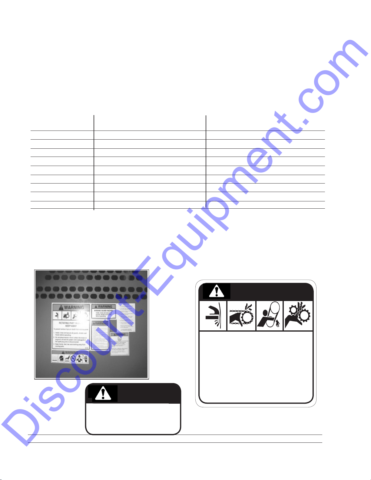
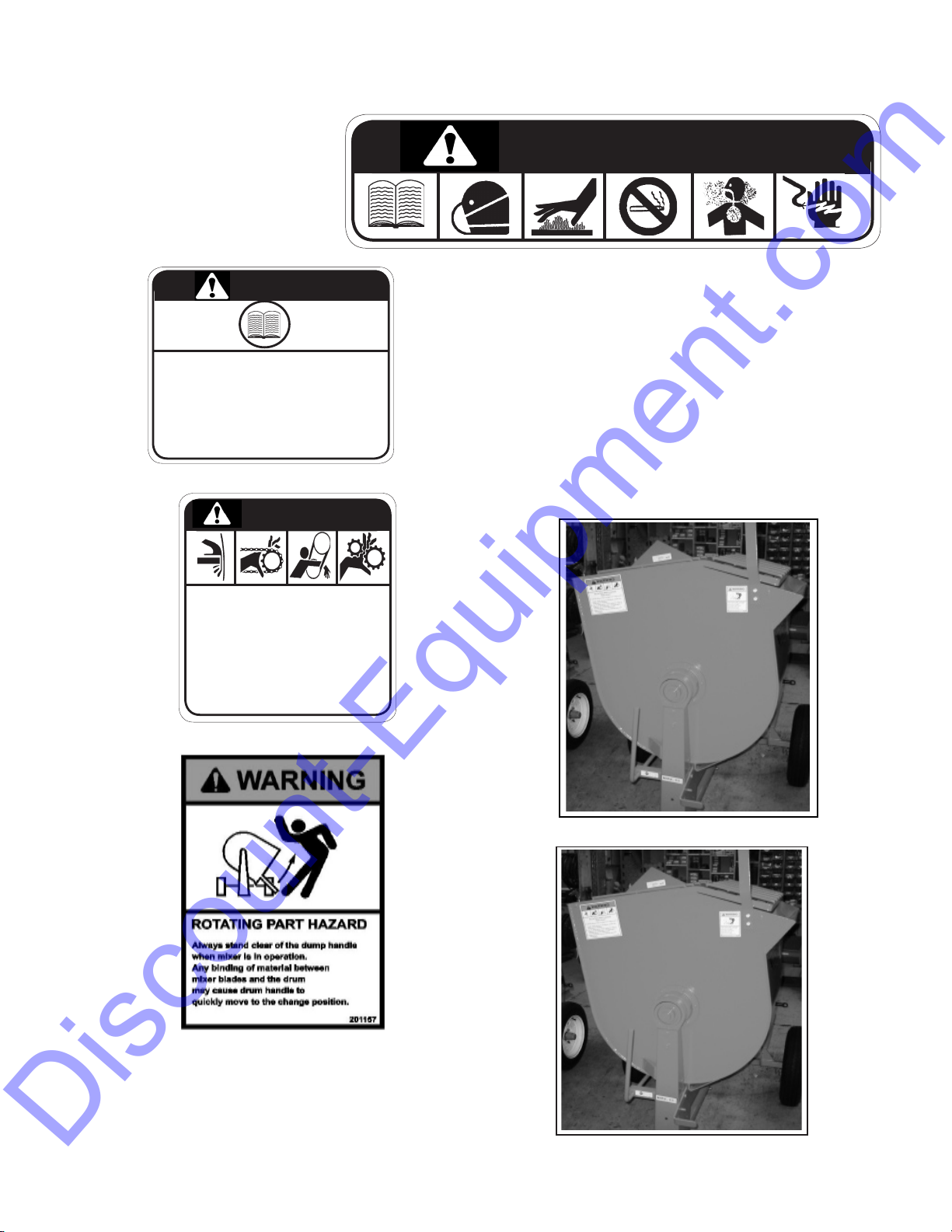
3 SAFETY SIGN LOCATIONS
The types of safety signs and locations on the equipment are shown in the illustration below. Good safety requires
that you familiarize yourself with the various Safety Signs, the type of warning and the area, or particular function
related to that area, that requires your SAFETY AWARENESS.
•ThinkSAFETY!WorkSAFELY!
A
WARNING
B
A
ROTATING PART HAZARD
KEEP AWAY
201003
D
C
B
WARNING
MISSING GUARD HAZARD
Install, close and secure all
guards, shields and hoods before
201004
operating.
To prevent serious injury or death from rotating parts:
1. Install, close and secure all guards, shields and hoods
before operating.
2. Do not place hands in drum unless the motor or engine
is o and the power cord unplugged or the spark plug
wire is disconnected.
3. Keep hands, feet, hair and clothing away from moving
parts.
7
Page 10
REMEMBER - If Safety Signs
Discount-Equipment.com
have been damaged, removed,
become illegible or parts
replaced without safety signs,
new signs must be applied.
New safety signs are available
from your authorized dealer.
C
D
WARNING
201353
WARNING
Improper operation of this equipment can cause serious
injury or death.
Read Operator's Manual supplied with this machine before
operation or service.
Modication or alteration of this machine can cause serious
injury or death.
Do not alter or modify this machine without the express
written consent of the manufacturer.
201154
E
WARNING
ROTATING PART HAZARD
KEEP AWAY
To prevent serious injury or death from rotating parts:
1. Install, close and secure all guards, shields and hoods
before operating.
2. Do not place hands in drum unless the motor or engine
is o and the power cord unplugged or the spark plug
wire is disconnected.
3. Keep hands, feet, hair and clothing away from moving
parts.
201003
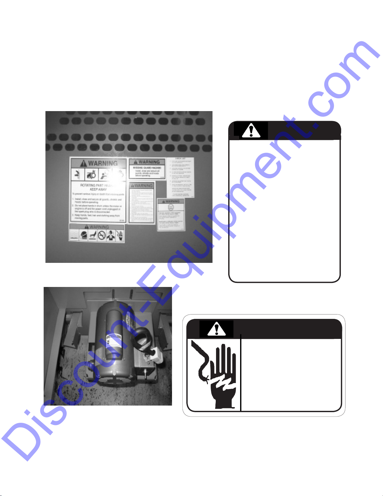
3 SAFETY SIGN LOCATIONS
The types of safety signs and locations on the equipment
are shown in the illustration below. Good safety requires
that you familiarize yourself with the various Safety Signs,
the type of warning and the area, or particular function
related to that area, that requires your SAFETY AWARENESS.
•ThinkSAFETY!WorkSAFELY!
E
F
E
REMEMBER - If Safety Signs have been damaged,
removed, become illegible or parts replaced without
safety signs, new signs must be applied. New safety
signs are available from your authorized dealer.
F
8
Page 11

3 SAFETY SIGN LOCATIONS
Discount-Equipment.com
GAS ENGINE POWER UNIT
The types of safety signs and locations on the equipment are shown in the illustration below. Good safety requires
that you familiarize yourself with the various Safety Signs, the type of warning and the area, or particular function
related to that area, that requires your SAFETY AWARENESS.
•ThinkSAFETY!WorkSAFELY!
DECAL 'G' ~ ALSO LOCATED ON
OUTSIDE OF HOOD
G
G
1. Read and understand Operator's Manual and safety signs
before starting.
2. Stop engine, disconnect spark plug wire and wait for all
moving parts to stop before servicing, maintaining, adjusting or cleaning.
3. Keep hands, feet, hair and clothing away from moving parts.
4. Install, close and secure all guards, shields and hoods before
operating.
5. Do not place hands in the drum unless engine is OFF and
spark plug wire is disconnected.
6. Stay away from hot engine components during operation.
7. Do not smoke when refueling.
8. Follow good safety procedures when handling fuel.
9. Do not operate in an explosive atmosphere or a poorly
ventilated area without adequate ventilation.
10. Keep working area dry and clean to prevent slipping and
tripping.
11. Always attach safety chain when towing.
12. Comply with applicable transporting regulations when towing.
13. Do not allow riders during transporting.
14. Do not exceed a safe travel speed when transporting. Slow
down for corners and when going over rough terrain.
WARNING
H
201001
H
REMEMBER - If Safety Signs have been damaged,
removed, become illegible or parts replaced without
safety signs, new signs must be applied. New safety
signs are available from your authorized dealer.
J
10
USE
GASOLINE
FUEL ONLY
201152
DANGER
J
FIRE HAZARD
To prevent serious injury or death from re:
1. Do not smoke when refueling.
2. Keep sparks, ames and hot material away from ammable
substances.
NO SMOKING
201005
Page 12
3 SAFETY SIGN LOCATIONS
Discount-Equipment.com
ELECTRIC MOTOR POWER UNIT
The types of safety signs and locations on the equipment are shown in the illustration below. Good safety requires
that you familiarize yourself with the various Safety Signs, the type of warning and the area, or particular function
related to that area, that requires your SAFETY AWARENESS.
•ThinkSAFETY!WorkSAFELY!
DECAL 'H' ~ ALSO LOCATED ON OUTSIDE OF
HOOD
K
K
1. Read and understand Operator's Manual and safety signs
before starting.
2. Turn motor o, unplug power cord or turn o power at
master panel and wait for all moving parts to stop before
servicing, maintaining, adjusting or cleaning.
3. Keep hands, feet, hair and clothing away from moving parts.
4. Install, close and secure all guards, shields and hoods before
operating.
5. Do not place hands in the drum unless engine is OFF and
power cord is unplugged.
6. Have a licensed electrician wire up and provide power to the
electric motor.
7. Use a power cord with the required capacity to carry the
power to the motor.
8. Route the power cord out of the way or protect it from damage.
9. Do not operate in an explosive atmosphere or a poorly
ventilated area without adequate ventilation.
10. Keep working area dry and clean to prevent slipping and
tripping.
11. Always attach safety chain when towing.
12. Comply with applicable transporting regulations when towing.
13. Do not allow riders during transporting.
14. Do not exceed a safe travel speed when transporting. Slow
down for corners and when going over rough terrain.
15. Review safety instructions annually.
CAUTION
201002
L
L
REMEMBER - If Safety Signs have been damaged,
removed, become illegible or parts replaced without
safety signs, new signs must be applied. New safety
signs are available from your authorized dealer.
11
DANGER
ELECTROCUTION HAZARD
1. Turn machine OFF, shut down and
lock out power source, unplug pow-
er cord and wait for all moving parts
to stop before servicing or repairing
machine or electrical components.
2. Keep electrical components in good
repair.
201006
Page 13

3 SAFETY SIGN LOCATIONS
Discount-Equipment.com
The types of safety signs and locations on the equipment are shown in the illustration below. Good safety requires
that you familiarize yourself with the various Safety Signs, the type of warning and the area, or particular function
related to that area, that requires your SAFETY AWARENESS.
•ThinkSAFETY!WorkSAFELY!
M
WARNING
M
105
km/h
N
P
NOTICE
Ensure tow vehicle has towing capacity for the weight of this
machine.
Do not tow the machine unless the draw bar is bolted in
place and the safety bolt on the end of the draw bar is
securely fastened.
Close engine fuel cuto (where applicable) before towing
mixer to prevent leakage into the engine crankcase.
Use 2 people to lift and position hitch (pintle and ball) on
and o tow vehicle.
Securely attach hitch to towing vehicle - pintle or ball type
coupler (ball type shown).
Be certain ball clamp captures ball and lever or handwheel
is fully clamped. Ensure use of safety pin through latch or
handwheel (for ball type coupler).
Safety chain attachment (see illustration) chains must cross
under the draw bar and be positioned to prevent the draw
bar from dropping to the ground in the event of a hitch
failure.
Connect lighting plug/electric brake
plug (where applicable).
Make certain that the wheel lug nuts
and axle mounting hardware are tight.
Check pressure and overall
condition of tires.
Test brakes
(if applicable).
201001
201150
Excessive towing speed can cause serious
injury or death.
Do NOT exceed 65 mph (105 km/h)
1. Make certain that the wheel lug nuts and axle
mounting hardware are tight.
2. Check pressure and
overall condition of
tires.
N
P
CAUTION
Use 2 people to lift and position hitch on and o tow
vehicle.
REMEMBER - If Safety Signs have been damaged, removed, become illegible or parts
replaced without safety signs, new signs must
be applied. New safety signs are available from
your authorized dealer.
201151
201155
12
Page 14

4 OPERATION
Discount-Equipment.com
1. Read and understand the Operator’s Manual
and all safety signs before operating, servicing,
adjusting, or cleaning the Mixer.
2. Do not allow riders on the machine during transport.
3. Install, close and secure all guards, shields and
hoods before starting or operating.
4. Stop engine or motor, disconnect spark plug wire
or unplug power cord, and wait for all moving
parts to stop before servicing, adjusting, repairing, or cleaning.
5. Clear the area of all bystanders before starting.
6. Keep hands, feet, hair and clothing away from
moving parts.
7. Keep working area clean and dry to prevent slipping and tripping.
8. Do not run the mixer in an explosive atmosphere
or in a poorly ventilated or enclosed area.
OPERATING SAFETY
Slow down for corners and when going over
rough terrain.
12. Review safety instructions with all operators
annually.
Gas engine powered units:
• Do not place hands in the drum unless the en-
gine is OFF and the spark plug wire is disconnected.
• Stay away from hot engine components dur-
ing operation.
• Do not smoke when refueling gas engine.
Electric motor powered units:
• Do not place hands in the drum unless the mo-
tor is OFF and the power cord unplugged.
• Have a licensed electrician wire up and provide
power to the motor.
• Only use a power cord that is grounded.
9. Wear appropriate hearing protection when operating for long periods of time.
10. Always attach safety chain when towing.
11. Do not exceed a safe travel speed when towing.
4.1 TO THE NEW OPERATOR OR OWNER
The Crown Construction Equipment Mortar Mixer is
designed to eciently combine water, lime, aggregate and cement into a mixture for forming mortar. It
is the responsibility of the operator to be familiar with
the machine before starting.
It is the responsibility of the owner or operator to
read this manual before starting. Follow all safety
instructions exactly. Safety is everyone's business. By
following recommended procedures, a safe working
environment is provided for the operator, bystanders
and the environment.
• Always use an electrical cord with the required
power carrying capacity.
Many features incorporated into this machine are the
result of suggestions made by customers like you.
Read this manual carefully to learn how to operate the
machine safely and how to set it to provide maximum
mixing eciency. By following the operating instructions
in conjunction with a good maintenance program, your
Mixer will provide many years of trouble-free service.
13
Page 15

4.2 HOW THE MACHINE WORKS
Discount-Equipment.com
The Mortar Mixer consists of a large tilting drum with
internal rotating paddles or spiral blades for combining
cement, lime, aggregate and water into a mixture for
forming mortar. The enclosure on the back end houses
the electric motor or gas engine for turning the mixing elements. A set of pulleys and drive belt within the
enclosure transmits rotational power to a gearbox that
powers the mixing elements.
A lever on the front end of the drum assembly allows
the operator to tilt the drum to the required position
for mixing and emptying. A lever on the bottom of the
frame extends to the power compartment and moves
the gearbox to engage the drive belt for turning the mixing elements. An extendable hitch allows the hitch to
extend for towing and retracts during operation.
H
L
M
P
O
K
Fig. 1 MACHINE COMPONENTS
A Gas Engine
B Electric Motor
C Belt/Pulley Drive
D Gearbox
E Power Compartment
F Paddles
G Spiral Blades
H Grill
G
J Bag Splitter
K Drum
L Tilt Lever
M Drum Lock
N Engagement Clutch
O Hitch
P Safety Chain
Q Emergency Stop
14
J
H
Q
K
E
N
Page 16

4.3 PRE-OPERATION CHECKLIST
Discount-Equipment.com
Ecient and safe operation of the Mixer requires that
each operator reads and understands the operating
procedures and all related safety precautions outlined
in this section. A pre-operation checklist is provided
for the operator. It is important for both personal
safety and maintaining the good mechanical condition of the machine that this checklist is followed.
Before operating the Mixer and each time there-after,
the following areas should be checked o:
1. Gas Engine Units:
a. Check all uid levels: fuel, engine oil and
gearbox oil. Refuel or top up oil as required.
b. Check the tires and be sure that they are
inated to the specied pressure.
c. Check the tension and alignment of drive belt
when engaged. Tension or align as required.
d. Lubricate machine per Maintenance Section.
e. Close and secure all guards, shields and hoods.
4.4 PRE-START PROCEDURES
All machines are sent from the factory in a special shipping conguration to prevent spilling oil or gas. As a
result, the following items must be done prior to starting the machine:
1. Gas engine powered units:
a. Fill the engine crankcase with its specied oil
(SAE 30W or 10W30 oil).
IMPORTANT
Engine warranty is void if the
Refer to engine manual for oil specications if
engine is run without oil.
operating in unusual temperature conditions.
d. Check the engine speed at maximum. Be sure
it is set to give a paddle rotation speed of 3035 RPM and a spiral rotation of 40-45 RPM.
e. Use the emergency stop switch to stop the
engine to be sure that it works. Repair or
replace if it is not functioning.
f. Lubricate machine per Maintenance Section.
g. Close and secure all guards, shields and
hoods.
2. Electric motor units:
a. Check the tension and alignment of drive
belt when engaged. Tension and align as
required.
b. Check gearbox oil level. Top up as required.
c. Check the tires and be sure that they are
inated to the specied pressure.
b. Add SAE 80W90 oil to the gearbox.
c. Fill the fuel tank with regular unleaded gas. Do
not use an ethanol blend.
d. Start the engine and set the high idle speed
to give a mixing element rotation speed of 30
to 35 RPM for the paddles and 40 to 45 for the
spiral.
IMPORTANT
The engine is supplied from the engine
manufacturer with the high idle speed set at
approximately 3500 RPM and no gas or oil.
As a result, the engine is not run when it is
mounted to the Mixer. It is the responsibility
of the customer to add oil and gas, start the
engine and reset the high idle RPM to the operating range (Refer the Maintenance Section
for procedure).
e. The machine is shipped with the drum tilt
lever pointing down or fastened to the safety
grill. Remove lever and turn it around so it is
pointing up. Tighten mounting bolts to their
specied torque.
f. Be sure the emergency stop switch is function-
ing properly.
15
Page 17

4.4 PRE-START PROCEDURES
Discount-Equipment.com
(Cont'd)
2. Electric motor powered units:
4.6 CONTROLS
Before starting to work, all operators should familiarize themselves with the location and function of the
controls.
a. Have a licensed electrician provide power to the
motor. Use only a grounded cord with sucient
capacity to carry the required load.
b. Have a licensed electrician wire up the motor if it is
not a 110 volt unit.
c. The machine is shipped with the drum tilt lever
pointing down. Remove lever and turn it around
so it is pointing up. Tighten mounting bolts to their
specied torque.
4.5 MACHINE BREAK-IN
A special break-in procedure has been developed to insure the
integrity of the machine when rst starting. When using the
machine for the rst time, follow this procedure.
A. Before Starting:
1. Read the engine and Mixer Operator's Manuals.
2. Review and follow pre-start procedures before starting machine (Section 4.4).
B. At 1/2, 2, 5 and 10 hours:
1. Check all machine uid levels: Fuel, engine oil and
gearbox oil. Refuel or top up as required.
2. Retorque wheel bolts.
3. Check for loose hardware. Tighten to specied torque.
4. Check drive belt tension and alignment when engaged. Tension and align as required.
1. Gas engine powered units:
Always read the engine Operator's Manual supplied
with the machine for the detailed operating procedures for your engine.
a. Ignition switch:
This switch controls the electrical power to the
engine electrical system. Turn the switch clockwise to turn the electrical system ON and the
engine will run. Turn counterclockwise to stop
the engine.
b. Fuel shuto valves:
Each engine is equipped with a shut-o valve
between the fuel tank and the carburator. Slide
the fuel valve toward the block to turn ON and
away for OFF. Turn the fuel OFF when not in use
or before transporting.
c. Throttle:
This lever controls the engine RPM. Move the
lever laterally to increase or decrease the RPM.
Always run at maximum throttle operating.
d. Choke:
The choke controls the fuel/air mixture to the
engine. Close the choke when starting if the
engine is cold. Open the choke as the engine
warms. Always open the choke fully during
operation.
e. Starting rope:
This retracting rope and T bar is used to turn the
engine over for starting. Grasp the T bar rmly
and pull the rope sharply to start the engine.
Close the choke if the engine is cold.
5. Lubricate the points dened in the Maintenance section.
6. Then go to the service schedule as dened in the
Maintenance section.
C. At 10 hours:
1. Change the engine oil.
2. Change the gearbox oil.
3. Replace with their specied oil.
4. Then go to the oil replacement schedule as dened in
the Maintenance section and engine manual.
f. External Emergency Stop Switch:
This push-pull switch shorts out the power to
the gas engine ignition system and is located
on the outside of the hood. Push the switch
in to stop the engine and pull out to allow it
to run.
16
Page 18

c
Discount-Equipment.com
d
b
e
Honda
Fig. 2 GAS ENGINE CONTROLS
5. Drive Engagement Clutch:
This lever engages and disengages the mixing ele-
ments in the drum. Move to the left to disengage
the drive and ease to the right to engage. Always
disengage before starting the engine or motor and
a
Switch
Fig. 4 ELECTRIC MOTOR (TYPICAL)
Fig. 3 EXTERNAL EMERGENCY STOP
SWITCH (TYPICAL)
2. Electric Motor (Typical):
a. Master ON/OFF:
This switch controls the power to the electric
motor that turns the mixing elements in the
drum. Move the switch rearward to turn ON
and forward for OFF.
WARNING
Machine is shown with engine hood open
for illustrative purposes only. Never operate with hood open.
3. Drum Position:
This lever sets the position of the mixing drum.
Move the lever down to empty the drum and
up to mix.
4. Drum Position Lock:
This lever locks the mixing drum in its mixing
position. Pull up on lever to release the lock.
It will automatically engage when the drum is
moved into its mixing position.
3
5
4
Fig. 5 DRUM EMPTYING CONTROLS
17
Page 19

4.7 OPERATING
Discount-Equipment.com
1. Read and understand the Operator’s Manual
and all safety signs before operating, servicing,
adjusting, or cleaning the Mixer.
2. Do not allow riders on the machine during transport.
3. Install, close and secure all guards, shields and
hoods before starting or operating.
4. Stop engine or motor, disconnect spark plug wire
or unplug power cord, and wait for all moving
parts to stop before servicing, adjusting, repairing, or cleaning.
5. Clear the area of all bystanders before starting.
6. Keep hands, feet, hair and clothing away from
moving parts.
7. Keep working area clean and dry to prevent slipping and tripping.
8. Do not run the mixer in an explosive atmosphere
or in a poorly ventilated or enclosed area.
OPERATING SAFETY
Slow down for corners and when going over
rough terrain.
12. Review safety instructions with all operators
annually.
Gas engine powered units:
• Do not place hands in the drum unless the en-
gine is OFF and the spark plug wire is disconnected.
• Stay away from hot engine components dur-
ing operation.
• Do not smoke when refueling gas engine.
Electric motor powered units:
• Do not place hands in the drum unless the mo-
tor is OFF and the power cord unplugged.
• Have a licensed electrician wire up and provide
power to the motor.
• Only use a power cord that is grounded.
9. Wear appropriate hearing protection when operating for long periods of time.
10. Always attach safety chain when towing.
11. Do not exceed a safe travel speed when towing.
Each operator should review this section of the manual
when starting a project and as often as required to be
familiar with the machine. When operating, follow this
procedure:
1. Review and follow the Pre-Start and Pre-Operation
checklists.
2. Review the location and function of all controls.
3. Determine ratio of the cement, lime, water and aggregate required for your mixture. Always use the
same mixture ratio for each batch.
4. Be sure the mixing elements turn at 30 to 35 RPM
for the paddles and 40 to 45 RPM for the spiral to
insure proper mixing.
• Always use an electrical cord with the required
power carrying capacity.
Fig. 6 ELECTRICAL POWER SWITCH (TYPICAL)
19
Page 20

5. Starting machine:
Discount-Equipment.com
A. Electric motor powered units:
a. Check that everyone is clear of the ma-
chine.
b. Move power engagement clutch to the
left to disengage the mixing elements.
c. Unlatch and open the hood.
d. Turn the power switch ON.
e. Close and latch the hood.
f. Move power engagement clutch to the
right to engage the mixing elements.
B. Gas engine powered units:
a. Check that everyone is clear of the ma-
chine.
b. Pull the emergency stop switch out.
c. Move power engagement clutch to the
left to disengage the drive.
d. Unlatch and open the engine compart-
ment hood.
e. Move the throttle into its midrange posi-
tion.
f. Close the choke if starting when the
engine is cold.
g. Turn the ignition switch to its RUN posi-
tion.
h. Pull sharply on the T bar rope to start the
engine.
i. Allow the engine to run for a couple of
minutes to warm up.
j. Open the choke to its fully open position
when the engine is warm.
k. Move the throttle to its maximum RPM
position.
Fig. 7 EMERGENCY STOP SWITCH (TYPICAL)
IMPORTANT
Be sure the engine has been set
to give a mixing element speed
of 30 to 35 RPM for the paddles
l. Close and secure the engine compart-
m. Ease the power engagement clutch to
and 40 to 45 RPM for the spiral.
ment hood.
Fig. 8 POWER ENGAGEMENT CLUTCH
the right to engage the mixing elements.
WARNING
Machine is shown with engine hood
open for illustrative purposes only.
Never operate with hood open.
20
Page 21

6. Stopping machine:
Discount-Equipment.com
A. Electric motor powered units:
a. Move the power engagement clutch to
the left to disengage the mixing ele-
ments.
b. Empty the drum of the mortar mixture.
c. Unlatch and open the hood.
d. Turn the power switch OFF.
e. Close and latch the hood.
B. Gas engine powered units:
a. Move the power engagement clutch to
the left to disengage the mixing ele-
ments.
b. Empty the drum of the mortar mixture.
c. Unlatch and open the hood.
d. Move the throttle to its low idle position.
e. Stop the engine by turning the switch
OFF or depressing the kill switch or strap.
f. Close and secure the engine compart-
ment hood.
Power Switch
7. Emergency Stopping:
If an emergency arises, stop the machine by mov-
ing the power engagement clutch to the left to
disengage the mixing elements and then pushing
the kill switch in.
8. Machine placement:
Always place the Mixer in a location so the opera-
tor has easy access to the mixture ingredients
when adding to the mixing drum. Always position to
provide adequate clearance for the machine or
equipment removing the concrete mixture from the
mixing drum. On the electric motor models, route
the power cord out of the way to prevent damage.
Do not run the mixture in an explosive atmosphere
or in a poorly ventilated or enclosed area.
9. Filling:
When mixing mortar, follow this procedure:
a. Clear the working area of unauthorized person-
nel.
b. Start the motor or engine.
c. Engage the mixing elements.
d. Add half the required amount of water into the
mixing drum.
e. Add half the required amount of sand into the
drum.
f. Add the required mortar mix (cement, lime,
etc.).
g. Add the cement required for the batch.
h. Add the rest of the water.
i. Add the rest of the sand until the desired work-
ability is obtained.
21
External Emergency Stop Switch (Typical)
Fig. 9 STOPPING
WARNING
Machine is shown with engine
hood open for illustrative purposes
only. Never operate with hood
open.
NOTE
Add sand a little at a time until
the desired consistency is
obtained.
j. Mix until there is an even consistency
throughout the mixture. Look into the drum
and watch until the mixture is the same
color throughout. This means the mortar
mix is evenly distributed throughout the
mixture.
k. Disengage the mixing clutch.
l. Release the drum lock and slowly tilt the
drum down to discharge the mixture.
m. Raise the hinged grill out of the way when
discharging the mixture.
n. Move the drum back into its mixing position
and lock. Immediately engage the mixing
clutch and add half the water for the next
batch. This will help to keep the drum and
mixing elements clean and prevent lumps
from forming in the mortar.
Page 22

10. Mixing time:
Discount-Equipment.com
After all the ingredients have been added to the
drum, allow time for the material to reach a uniform
color and consistency. Watch the color and consistency of the mixture as the drum is turning. When
the entire mixture becomes a pale green color,
it means the mortar mix is uniformly distributed
throughout the mixture and can be discharged. If
the mixture is not uniform, the mortar will have
weak spots.
11. Emptying drum:
All Mixers are equipped with a lock for anchoring
the drum at the mixing angle. Move the wheelbarrow or other mortar receiver up to the side of the
Mixer. To empty the drum:
a. Disengage mixing clutch.
b. Release drum lock.
c. Move the wheelbarrow into position.
d. Slowly tilt the drum down.
e. Lift the hinged grill out of the way.
f. Fill the wheelbarrow.
g. Raise the drum back into its mixing position
and lock.
h. Engage mixing clutch.
i. Add half the water and sand for the next
batch. This will help to clean the mixing ele-
ments and inside of the drum.
NOTE
The Mixer is equipped with a solid grill
and bag splitter over the drum opening.
Place the bag of material on the grill/splitter and let the material fall into the drum.
Repeat with the next bag until the required
amount is added.
12. Mixing Elements:
A Mixer can be equipped with paddles or a spiral for
mixing the materials into a uniform mixture. Each
system has adjustable wipers to clean the sides and
ends of the drum. Maintain the wipers at 1/16 to
1/8 inch (1.5 to 3.0 mm) from the drum surface. A
large gap can result in a build-up on the surface.
This build-up will break loose and produce lumps or
chips in the mixture.
13. Preventing Build-up:
To maintain high quality mixing, consistent per-
formance and machine life, thoroughly clean the
mixer inside and out at the end of each day.
Under normal operating conditions, adding water
and sand and some aggregate to the drum immediately after emptying will wash and clean the mixing
elements and the inside of the drum and keep them
clean providing the wipers are set at 1/16 to 1/8
inch (1.5 to 3 mm) from the drum surface. If a slow
build-up is occurring, add water and coarse sand to
the drum at the end of the working day and let it
run for 15 minutes.
Fig. 10 FILLING
14. Removing Build-up:
Always disable the machine by unplugging the
power cord or disconnecting the spark plug wire.
Dried mix should be scraped out as necessary. DO
NOT strike the outside of the drum with a shovel,
hammer or other device to break up and loosen any
build-up, as this will dent and damage the drum.
At the end of the working day, thoroughly wash the
inside of the drum and the outside of the machine to
remove any residue build-up or clumps. Do not get
water on the electric motor or gas engine.
15. Drum speed:
The best mixing action occurs when the mixing ele-
ments are turning 30 to 35 RPM for the paddles and
40 to 45 for the spiral. Do not operate outside of this
speed range. Increasing the mixing element speed
does not signicantly change mixing characteristics.
Mixing time is much more important and the mixture must be thoroughly blended to obtain uniform
and consistent mortar.
22
Page 23

16. Capacities:
Discount-Equipment.com
Each model has its own specied capacity.
When that capacity is exceeded, the excess spills out
of the drum making a mess of the working area and
increases the required time for mixing. It is recommended to use an additional mixer if more mixing
capacity is required.
NOTE
On the larger models, a full drum
can ll more than one wheelbarrow. Change wheelbarrows until
the drum is empty.
Fig. 11 EMPTYING DRUM
G
1. Read and understand Operator's Manual and safety signs
before starting.
2. Stop engine, disconnect spark plug wire and wait for all
moving parts to stop before servicing, maintaining, adjusting or cleaning.
3. Keep hands, feet, hair and clothing away from moving parts.
4. Install, close and secure all guards, shields and hoods before
operating.
5. Do not place hands in the drum unless engine is OFF and
spark plug wire is disconnected.
6. Stay away from hot engine components during operation.
7. Do not smoke when refueling.
8. Follow good safety procedures when handling fuel.
9. Do not operate in an explosive atmosphere or a poorly
ventilated area without adequate ventilation.
10. Keep working area dry and clean to prevent slipping and
tripping.
11. Always attach safety chain when towing.
12. Comply with applicable transporting regulations when towing.
13. Do not allow riders during transporting.
14. Do not exceed a safe travel speed when transporting. Slow
down for corners and when going over rough terrain.
WARNING
Paddles
201001
Spiral
Table 1 Capacity Bags
4S
5S
S5S
6S
6SR
S6SR
6PR
S8S
8S
8P
10S
S10S
12S
S12S
1 - 1-1/2
2 - 2-1/2
3 - 3-1/2
3 - 4
23
Page 24

17. Power Engaging Clutch:
Discount-Equipment.com
The power engaging clutch lever is located
next to the drum tilting controls so it is
convenient for the operator to stop the
mixing elements when emptying the
drum. The linkage in the power compartment must be set so the drive belt does
not slip during operation and the operator must feel the lever go over-center as
it fully engages. Always disengage the
clutch when starting, stopped or emptying.
WARNING
Machine is shown with engine hood open
for illustrative purposes only. Never operate with hood open.
Linkage
18. Selection of Mortar type:
The performance of masonry is inuenced
by various mortar properties such as workability, bond strength, durability, extensibility and compression strength. Since
these properties vary with mortar type, it
is highly important that the mortar type
selected for a particular application is the
one that best meets the end-user requirements. Table 1 is a general guide for the
selection of for various masonry wall construction. Selection of mortar type should
also be based on the type of masonry units
to be used as well as the applicable building code and engineering practice standard requirements such as allowable design
stresses and lateral support.
Fig. 14 POWER ENGAGING CLUTCH SYSTEM
25
Lever - Engaged
Lever - Disengaged
Page 25

19. Guide for the selection of masonry Mortars
Discount-Equipment.com
TABLE 1 MORTAR TYPE:
Location Building Segment Recommended Alternative
Exterior, above grade Loadbearing wall N S or M
Non-loading wall, Parapet wall, N OB or S
chimney & veneer wall N S
Exterior, at or Foundation wall, retaining wall, M SC or N
below grade manholes, sewers pavements
walks and patios
Interior Loadbearing wall N S or M
Non loadbearing partitions. O N
A
This table does not provide for many specialized mortar used, such as reinforced masonry, acid resistant and re box mortars.
B
Type 0 mortar is recommended for use where the masonry is unlikely to be frozen when saturated or unlikely to be subject to high winds
or other signicant lateral loads. Type N or S mortar should be used in other cases.
C
Masonry exposed to weather in a nominally horizontal surface is extremely vulnerable to weathering. Mortar for such masonry should be
selected with due caution.
TABLE 2 MORTAR PROPORTIONS BY VOLUME
A
C
Parts by Parts by Aggregate ratio
volume of volume of (measured in
Mortar Portland hydrated damp, loose
type cement lime conditions)
M 1 1/4 Not less than 2 1/4
S 1 Over 1/4 to 1/2 and not more than 3
N 1 Over 1/2 to 1 1/4 times the sum of the
O 1 Over 1 1/4 to 2 1/2 volumes of cement
and lime used.
TABLE 3 PROPERTY SPECIFICATION REQUIREMENTS
Average compressive
strength at Water Air Aggregate ratio
Mortar 28 days, min psi retention content (measured in damp
type (MPa) min % max % loose conditions)
M 2500 (17.2) 75 12 Not less than 2 1/4 and
S 1800 (12.4) 75 12 not more than 3 1/2 times
N 750 (5.2) 75 14 the sum of the separate
O 350 (2.4) 75 14 volumes of cementitious
materials.
26
Page 26

20. Volumes and weights of materials:
Discount-Equipment.com
1 Bag of Cement 88 lb 1 Bag of Cement 40 Kg
1 Cu. ft. Sand/Gravel 85-100 lb 1 Cu. metre Sand/Gravel 1360-1600 Kg
1Cu. ft. Plain Concrete 140-150 lb 1Cu. metre Plain Concrete 2240-260 Kg
1 Cu. ft. Water 62-65 lb 1 litre Water 1 kg
1 Imperial Gallon of Water 10 lb 1 Cu. metre Water 1000 kg
1 Cu. Yard 27 cu. ft. = 7646 cu. metre
21. Operating hints:
a. Keep the working area as clean and dry as pos-
sible to prevent slipping and tripping.
b. Provide sucient space around the machine for
adding material to the drum and removing the
mixture.
c. Always add the materials in the same ratio to give
a uniform mixture for mortar.
d. Provide sucient time to thoroughly combine
the mixture to a uniform consistency before discharging from the drum.
e. The water requirements for the mixture can vary
depending on moisture content of the sand. Vary
the amount of water in the mixture to give the
consistency of the mortar desired.
Crown Construction Mixers are designed to be easily and
conveniently moved from place to place.
When moving the machine, follow this procedure:
1. On the larger Models, extend the pole to its full
length.
2. Secure with the lock pin and retainer.
4.8 TRANSPORTING
TRANSPORT SAFETY
1. Read and understand ALL the information in
the Operator’s Manual regarding procedures
and SAFETY when operating the Mixer in the
workplace and/or on the road.
2. Always travel at a safe speed. Use caution
when making corners or on a rough surface.
3. Make sure all the lights and reectors that are
required by the local highway and transport
authorities are in place, are clean and can be
seen clearly by all overtaking and oncoming
trac.
4. Do not allow riders on any part of the machine during either road or highway travel.
5. Always use a safety chain between the Mixer
and the towing vehicle when transporting.
6. Use a mechanical retainer through the ball
hitch or clevis pin before transporting.
7. Ensure wheel nuts and axle hardware are
tight.
3. Use 2 men to lift the hitch and pull the Mixer to the
new location.
4. Retract and lock the pole.
When transporting the machine, follow this procedure:
1. On the electric motor powered units, unplug the
power cord.
Fig. 15 MOVING
27
Page 27

2. On gas engine powered units, open the
Discount-Equipment.com
hood and close the fuel valve to prevent
ooding the carburetor.
3. Move the drum to its mixing position and
lock.
4. Attach the optional lighting bar and secure.
5. On the larger Models, extend the hitch
pole and secure with the lock pin and
retainer.
6. Securely attach the machine to the towing
vehicle.
7. Use a mechanical retainer through the
ball hitch or the clevis pin.
IMPORTANT
Be sure the ball on the truck is
the correct size for the hitch. Do
not use an undersized ball with
the hitch.
Fig. 16 FUEL SHUT OFF VALVE
WARNING
Machine is shown with engine hood open
for illustrative purposes only. Never operate with hood open.
8. Attach the safety chain to prevent unexpected separation. Cross the chains
under the hitch for support.
9. Plug the wiring harness into the truck.
Be sure all the lights are working.
10. Check that the wheel bolts are tightened to their specied torque.
11. Check that the tires are inated to
their required pressure.
12. Use special care when transporting
during times of limited visibility. Be
sure that you can be seen by oncoming and overtaking trac. Always use
the lighting bar.
13. Never exceed the speed appropriate
for the terrain and conditions. Slow
down for turns and when traveling
over rough terrain.
Ball Hitch
Clevis
Fig. 17 ATTACHMENT
29
Page 28

4.9 STORAGE
Discount-Equipment.com
STORAGE SAFETY
1. Store unit in an area away from human activity.
2. Do not permit children to play on or around
the stored Mixer.
At the end of the season or when the machine will not
be used for a period, inspect all major components of the
Mixer. Repair or replace any worn or damaged components to prevent any unnecessary down time at the start
of next project. When preparing for storage, follow this
procedure:
1. Drain the fuel from gas tank.
5 SERVICE AND MAINTENANCE
MAINTENANCE SAFETY
1. Review the Operator's Manual and all safety
items before working with, maintaining or
operating the Mixer.
2. Stop engine or motor, disconnect spark plug
wire or unplug power cord, and wait for all
moving parts to stop before servicing, adjusting, repairing, or cleaning.
3. Follow good shop practices:
Keep service area clean and dry. Be sure elec-
trical outlets and tools are properly grounded.
Use adequate light for the job at hand.
2. Turn the fuel supply valve OFF or unplug the power
cord.
3. Close and secure the hood.
4. Thoroughly wash the machine using a water hose or
pressure washer to remove all dirt, dust or residue.
IMPORTANT
Do not get water on the electric
motor or gas engine. Use an
air hose to clean the motor or
engine.
5. Inspect the inside of the drum. Chip out or break loose
any build-up.
6. Lubricate all the grease ttings.
7. Rotate the drum so it is pointing straight down or in its
emptying position.
8. Cover the machine with a tarpaulin and tie down if the
machine is not stored inside.
4. Keep hands, feet, clothing and hair away from
all moving and/or rotating parts.
5. Do not place hands in the drum unless the
engine is o and the spark plug wire is discon-
nected or the power cord is unplugged.
6. Do not attempt any adjustment or maintenance to any system of the Mixer unless the
power source is disabled.
7. Make sure that all guards, shields and hoods
are properly installed and secured before operating the Mixer.
8. Securely support the machine using blocks
or safety stands before working beneath it or
changing tires.
9. Store and transfer gasoline, solvents, cleaners
or any ammable liquids only in safety standard approved containers.
5.1 SERVICE
5.1.1 FLUIDS AND LUBRICANTS
1. Grease
Use an SAE multi-purpose high temperature grease
or a multi-purpose lithium base grease.
2. Gasoline
Use a standard unleaded gasoline for all operating
conditions. Do not use gasoline with an ethanol
blend.
Fig. 18 STORED
31
Page 29

Capacities:
Discount-Equipment.com
5.5 Honda: 0.95 US Gal (3.6 Lts, 0.79 Imp Gal)
9.0 Honda : 1.59 US Gal (6.0 Lts, 1.32 Imp Gal)
3. Engine oil:
Use an SAE 10W30 multi-viscosity oil meeting the
American Petroleum Institute (API) classication
of SF OR SG for normal operating temperatures.
Consult the engine manual for unusual operating
conditions. Do not mix oil types or viscosities.
Crankcase Capacity:
5.5 hp: 0.53 US Qts (0.5 Lts, 0.44 Imp Qts)
9.0 hp: 1.16 US Qts (1.1 Lts, 1.94 Imp Qts)
4. Storing Lubricants and Fluids
Your machine can operate at top eciency only if
clean lubricants are used. Use clean containers to
handle all uids. Store them in an area protected
from dust, moisture and other contaminants.
5.1.2 GREASING
Refer to section 5.1.1 for recommended grease. Use the
Maintenance Checklist provided to keep a record of all
scheduled maintenance.
5.1.3 SERVICING INTERVALS
Daily or 8 Hours
1. Check engine uid levels. Top as required.
a. Check engine oil level. Top up as required.
b. Check fuel level. Add as required.
Fig. 22 CLUTCH LINKAGE SHAFT (TYPICAL)
b
a
Fig. 19 ENGINE FLUID LEVELS
2. Check the drive belt tension with the clutch
engaged.
WARNING
Machine is shown with engine hood open
for illustrative purposes only. Never operate with hood open.
Machine
Clutch Linkage
Fig. 20 DRIVE BELT TENSION
Daily or 8 Hours (cont'd)
3. Grease the drum assembly bearings (2 locations).
Fig. 21 DRUM ASSEMBLY BEARINGS
4. Grease the clutch linkage shaft
in the power compartment (1
location).
32
Page 30

Daily or 8 Hours (cont'd)
Discount-Equipment.com
5. Use an air hose to blow out and clean
the engine, motor and compartment.
WARNING
Machine is shown with engine hood open
for illustrative purposes only. Never operate with hood open.
Weekly or 50 Hours
1. Change the engine oil.
IMPORTANT
Change more frequently if operating in high ambient temperatures or in very dusty or dirty
conditions.
a. Drain plug.
b. Fill plug.
2. Clean the engine air intake lter.
Gas Engine (Typical)
Electric Motor
Fig. 23 DRIVE COMPARTMENT
Weekly or 50 Hours (cont'd)
3. Check the gearbox oil level.
Fig. 24 ENGINE OIL
Fig. 26 GEARBOX LEVEL & DRAIN PLUGS
Fig. 25 ENGINE AIR INTAKE FILTER
35
Fig. 27 ELECTRIC MOTOR
Page 31

Annually or 400 Hours
Discount-Equipment.com
1. Grease the electric motor bearings with
1/2 shot of grease (2 locations).
2. Change gearbox oil
3. Repack wheel bearings. (2 locations).
4. Check wheel nut torque.
5. Check axle mounting hardware.
Fig. 29 WHEELS
5.1.4 SERVICE RECORD
See Lubrication and Maintenance sections for details of service. Copy this page to continue record.
ACTION CODE: š CHECK C CHANGE CL CLEAN
L LUBRICATE RE REMOVE R REPACK
HOURS
SERVICED
BY
MAINTENANCE
DAILY OR 8 HOURS
š Engine Fluid Levels
š Engine Oil Level & Fuel Level
š Drive Belt Tension
L Drum Assembly Bearings (2)
L Clutch Linkage Shaft (1)
CL Engine, Motor & Compartment
WEEKLY OR 50 HOURS
C Engine Oil, Drain Plug & Fill Plug
CL Engine Air Intake Filter
š Gearbox Oil Level
ANNUALLY OR 400 HOURS
L Electric Motor Bearings (2)
C Gearbox Oil
R Wheel Bearings (2)
š Wheel Nut Torque
š Check Axle Mounting Hardware
37
Page 32

5.2 MAINTENANCE
Discount-Equipment.com
By following a careful service and maintenance
program for your machine, you will enjoy many
years of trouble-free service.
5.2.1 ENGINE OIL CHANGING
1. Review the Operator’s Manual for the
engine.
2. Allow the engine to cool before changing
oil. Hot oil can cause burns if it contacts
exposed skin. Draining works best if the
oil is warm.
3. Be sure the ignition switch is o and fuel
valve is turned o.
4. Place a pan under the drain plug.
5. Remove the drain plug and allow oil to
drain for 10 minutes.
6. Install the engine drain plug and tighten.
7. Dispose of the oil in an approved container.
8. Add the specied type and amount of motor oil. Refer to Section 5.1.1 or the engine
manual.
WARNING
Machine is shown with engine hood open
for illustrative purposes only. Never operate with hood open.
Fig. 30 ENGINE OIL CHANGING (DRAIN PLUG)
5.2.2 ENGINE SPEED SETTING
Every engine is shipped from the engine factory without gas or oil because of re hazards
during shipping. They are all set with a high
idle of 3500 RPM. Since no uids are added at
the Mixer factory, the RPM is not reset. When
the Mixer is delivered, the uids must be
added and the RPM reset. To reset the RPM,
follow this procedure:
9. Run the engine for 1 minute and check for
leaks.
10. If leaks are found around the drain plug,
tighten slightly and repeat Step 12.
11. Check engine oil level. Top up as required.
Fig. 31 ENGINE SPEED SETTING
1. Read the engine manual supplied with
the machine.
2. Add fuel and the specied motor oil to
the crankcase and oil to the gearbox.
3. Start the engine and run at wide open
throttle.
4. Use a screwdriver to reset the high idle
stop screw.
5. Count the mixing element revolutions to
determine engine RPM. Set the engine
speed to give 30-35 RPM for the paddles
and 40-45 RPM for the spiral when mixing.
6. Load the drum and count the mixing element rotational speed again.
7. Reset if the speed changes as required.
39
Page 33

5.2.3 AIR CLEANER MAINTENANCE
Discount-Equipment.com
Each engine is equipped with lter to remove dust
and dirt from entering the air intake. To clean
the lter, follow this procedure:
1. Read the engine manual supplied with the
machine.
2. Unlatch and open the hood.
3. Remove the lter cover.
4. Remove lter and shake out.
5. Wash in a lter cleaning detergent if
heavily caked with dirt. Allow time to dry
before re-installing.
6. Replace lter after washing 5 times.
7. Install clean lter and secure cover.
WARNING
Fig. 32 AIR CLEANER
5.2.4 BELT TENSION AND ALIGNMENT
A drive belt and pulley system transmits power from the
motor or engine to the gearbox for rotating the
mixing elements. A clutch lever through an over
center linkage swings the gearbox and pulley over
to tighten and engage the drive. The belt tension
must be properly set when the clutch is engaged
to prevent slipping and the pulleys aligned to prevent belt wear. To set the tension and alignment,
follow this procedure:
Machine is shown with engine hood open
for illustrative purposes only. Never operate with hood open.
Clutch Engaged
1. Unlatch and open hood.
2. Disable power source by unplugging power
cord or disconnecting spark plug wire.
3. Remove the pins on each end of the linkage
arm.
4. Lengthen or shorten linkage arm length by
turning yokes on the threaded rod.
5. Repin linkage arm.
6. Engage clutch. There should be a denite
feeling when the clutch linkage goes over
center. If not readjust linkage.
7. The belt is properly tensioned when the midspan deects 1/4 inch (6 mm) when pushed
on with a 10 lb force.
8. Align the pulleys by loosening the motor or
engine mounting bolts.
9. Slide or tap the power unit into position to
align the pulleys.
10. Tighten power unit mounting bolts to their
specied torque.
Clutch Linkage (Typical)
Fig. 33 BELT TENSION AND ALIGNMENT
11. Close and secure the hood.
41
Page 34

5.2.5 WIPER SPACING AND REPLACEMENT
Discount-Equipment.com
5.2.6 GEARBOX OIL CHANGING
Each machine is equipped with wipers on the mixing
elements to scrape the build-up from the inside of the
drum. After extended use, they will wear. They need to be
adjusted so they clean the sides of the drum. To adjust or
repair, follow this procedure:
1. Thoroughly clean the inside of the drum to remove all
the build-up.
2. Open hood and disable power source by unplugging
power cord or removing spark plug wire.
3. To adjust wipers, loosen mounting bolts.
4. Tap or slide wipers to 1/16 inch (1.5 mm) from the
drum.
5. Tighten mounting bolts to their specied torque.
6. If there is no more adjustment available, remove old
wipers.
7. Replace wipers.
8. Set at 1/16 inch (1.5 mm) from the drum.
9. Tighten mounting bolts to their specied torque.
The gearbox transmits power from the belt/pulley drive to the
mixing elements in the drum. As the gearbox breathes during its warming and cooling cycle, contaminants can enter
through the breather. Change the oil annually to remove
these contaminants
To change the oil, follow this procedure:
1. Open the hood.
2. Disable the power source by unplugging the power cord
or removing the spark plug wire.
3. Place a pan under the drain plug.
4. Remove the drain, level and ll plugs and allow the oil to
drain for 10 minutes.
IMPORTANT
Allow the gearbox to cool before
changing oil. Hot oil can cause
burns if it contacts exposed skin.
Draining works best if the oil is
warm.
5. Clean the drain plug.
6. Install the drain plug and tighten.
Paddles
7. Add 1 quart of SAE 80W90 gear oil through the ll plug.
8. When the oil in the gearbox just lls the threads of the
level plug, the gearbox is at the proper level.
9. Install the level and ll plugs and tighten.
IMPORTANT
If the air passage
through the breather
is plugged, soak the
breather in solvent for
an hour and blow out
with an air hose.
NOTE
There is a hole in the top of the
shroud (with a rubber plug) for
lling the gearbox.
c
b
a
a Drain b Level c Fill
Fig. 35 GEARBOX PLUGS
Fig. 34 WIPERS
Spiral
43
Page 35

6 TROUBLE SHOOTING
Discount-Equipment.com
The Crown Construction Mortar Mixer uses a large heavy-duty drum with mixing elements for combining water,
cement, lime and sand into a mixture for forming mortar. It is a well engineered machine that requires minimum
maintenance.
In the following trouble shooting section, we have listed many of the problems, causes and solutions to the problems
which you may encounter.
If you encounter a problem that is dicult to solve, even after having read through this trouble shooting section,
please contact your authorized dealer, distributor or the factory. Before you call, please have this Operator’s Manual
and the serial number from your machine ready.
PROBLEM CAUSE SOLUTION
Engine won’t start. No fuel. Fill the fuel tank.
Low engine oil. Fill the crankcase with oil.
Cold engine. Open choke.
Ignition switch o. Turn ignition switch on.
Kill switch o. Pull kill switch out.
Engine problem. Refer to engine manual.
Motor won't run. Power o. Turn power on at master panel.
Trip breaker at master panel.
Turn switch on at motor.
Overload switch tripped. Reset overload switch on motor.
Mixing elements won't turn. No power. Turn power on.
Start engine.
Loose drive belt. Adjust clutch linkage to tighten drive belt.
Belt o pulleys. Install belt and align pulleys.
Build-up on drum Wiper gap too Adjust wiper gap to 1/16 to 1/8 inch
walls. large. (1.5 to 3 mm).
Wipers worn out. Replace wipers.
Lumps or chips Drum build-up Clean build-up from drum
in mortar. breaking loose. walls and adjust wipers.
45
Page 36

7 SPECIFICATIONS
Discount-Equipment.com
SPECIFICATIONS SUBJECT TO CHANGE WITHOUT NOTICE
7.1 MECHANICAL
Model 4S 5S/S4S 6S 6SR/S6SR 6PR 8S/S8S 8P 10S 12S/S12S
Shaft R.P.M. Max: 38 46 38 38 38 32 32 32 32
Wrap Thickness: 10 USG 10 USG 10 USG 7 USG 1/4" 7USG 1/4" 7 USG 7 USG
End Plate Thickness: 7 USG 7 USG 7 USG 1/4" 1/4" 1/4" 1/4" 1/4" 1/4"
Drum Material: Steel Steel Steel Steel Polymer Steel Polymer Steel Steel
Drum Width: 23-1/4" 23-1/4" 23-1/4" 23-1/4" 23-1/4" 29-5/8" 29-5/8" 29-5/8" 29-5/8"
Drum Height: 24" 24" 27-1/2" 27-1/2" 31" 31" 31" 31" 31"
Drum Length: 26 3/4" 26 3/4" 26 3/4" 26 3/4" 26 3/4" 25-3/16" 25-3/16" 29-13/16" 33-3/4"
Capacity Bags: 1 to 1-1/2 1 to 1-1/2 2 to 2-1/2 2 to 2-1/2 2 to 2-1/2 2-1/2 to 3 2-1/2 to 3 3 to 3-1/2 3-1/2 to 4
Capacity Cubic Feet: 4 cu ft 4 cu ft 6 cu ft 6 cu ft 6 cu ft 8 cu ft 8 cu ft 10 cu ft 12 cu ft
Overall Height: 42-1/2" 42-1/2" 46" 56" 56" 54-1/2" 54-1/2" 54-1/2" 56"
Overall Width: 29-1/2" 29-12" 29-1/2" 49" 49" 49" 49" 49" 59"
Charging Height: 36-1/2" 36-1/2" 41" 49" 49" 49" 49" 49" 59"
Length - Tow Pole Out: 93" 93" 93" 93" 93" 93" 93" 97" 014"
Length - Tow Pole In: 65" 65" 65" 65" 65" 66" 66" 70" 83-1/2"
Tires (Pneumatic): 4.00 x 8 4.00 x 8 4.00 x 8 5.50 x 12 5.50 x 12 5.50 x 12 5.50 x 12 5.50 x 12 6.00 x 12
High Speed Bearings? NO No No Yes Yes Yes Yes Yes Yes
Gear reduction System? Yes Yes Yes Yes Yes Yes Yes Yes Yes
46
ELECTRIC POWER
HP 1/2 Hp 1 Hp 1.5 Hp 1.5 Hp 2 Hp 2 Hp 3 Hp 3 Hp 5 Hp 5Hp
Volts 110/220 110/220 110/220 230/460 110/220 230/460 220 230/460 220 230/460
Phase 1 1 1 3 1 3 1 3 1 3
Amps 8.4/4.2 12.4/6.2 18.0/9.0 4.8/2.4 20.4/10.2 6.4/3.2 16 8.6/4.3 23 14.0/7.0
Page 37

7.2 BOLT TORQUE
Discount-Equipment.com
CHECKING BOLT TORQUE
The tables shown below give correct torque values for various bolts and capscrews. Tighten all bolts to the torques
specied in chart unless otherwise noted. Check tightness of bolts periodically, using bolt torque chart as a guide.
Replace hardware with the same strength bolt.
Bolt
Dia.
"A"
1/4
5/16
3/8
7/16
1/2
9/16
5/8
3/4
7/8
1
Imperial Torque Specications
Bolt Torque*
SAE 2
Nm Ft-Lbs
8
13
27
41
61
95
128
225
230
345
SAE-2
6
10
20
30
45
60
95
165
170
225
SAE 5
Nm Ft-Lbs
12
25
45
72
110
155
215
390
570
850
SAE-5 SAE-8
9
19
33
53
80
115
160
290
420
630
Nm Ft-Lbs
SAE 8
17
36
63
100
155
220
305
540
880
1320
12
27
45
75
115
165
220
400
650
970
Metric Torque Specications
8.8
3
6
Bolt Torque*
Nm Ft-Lbs
2.2
4
7
18
37
66
103
166
321
553
4.5
9
15
35
70
125
200
310
610
1050
10.9
10.9
Bolt
Dia.
"A"
M4
M5
M6
M8
M10
M12
M14
M16
M20
M24
Nm Ft-Lbs
10
25
50
90
140
225
435
750
3.3
7
11
26
52
92
148
229
450
774
Torque gures indicated above are valid for non-greased or non-oiled threads and heads unless otherwise specied.
Therefore, do not grease or oil bolts or capscrews unless otherwise specied in this manual. When using locking elements, increase torque values by 5%.
WHEEL LUG NUT TORQUE:
Use the tightening pattern shown below, to ensure the even
tightening of the lug nuts on each wheel.
Bolt Bolt Torque
Dia Nm Ft-Lbs
1/2" 136 100
9/16" 203 150
* Torque value for bolts and capscrews are identied by their head markings.
47
Page 38

8 INDEX
Discount-Equipment.com
S
I
PAGE
Introduction ........................................................................1
O
Operation .......................................................................... 13
Controls......................................................................... 17
How The Machine Works ........................................ 14
Machine Break-In ....................................................... 16
Operating ..................................................................... 19
Pre-Operation Checklist .......................................... 15
Pre-Start Procedures ................................................ 15
Storage .......................................................................... 31
To The New Operator or Owner ........................... 13
Transporting ................................................................ 28
P
Proposition 65 .....................................................................i
Safety .....................................................................................2
General Safety ...............................................................3
Electrical Safety ............................................................. 6
Maintenance Safety .....................................................5
Operating Safety...........................................................4
Refueling Safety ............................................................6
Safety Signs ....................................................................6
Sign-O Form ................................................................7
Storage Safety ...............................................................5
Tire Safety ........................................................................5
Transport Safety ............................................................ 5
Safety Sign Locations .......................................................8
Service and Maintenance ............................................ 32
Maintenance ............................................................... 39
Air Cleaner Maintenance ................................... 41
Belt Tension and Alignment ............................. 42
Engine Oil Changing ........................................... 39
Engine Speed Setting ......................................... 40
Gearbox Oil Changing ........................................ 44
Wiper Spacing & Replacement ........................ 43
Service ............................................................................ 32
Fluids and Lubricants .......................................... 32
Greasing .................................................................. 32
Service Record ....................................................... 38
Servicing Intervals ............................................... 33
Specications ................................................................... 46
Bolt Torque................................................................... 47
Mechanical .................................................................. 46
PAGE
Serial Number
T
Trouble Shooting ............................................................ 45
SERIAL NUMBER LOCATION
Always give your dealer, distributor or factory the serial number of your Mortar Mixer
when ordering parts or requesting service or
other information.
The serial number plate is located where indicated and stamped into the frame. Please
mark the number in the space provided for
easy reference.
SERIAL NUMBER LOCATIONSModel
48
 Loading...