

Page 1
RPA-RMT
Installation Guide
Introduction
The RPA-RMT is a two-channel, wallmount remote volume control for use
with the P.I.P.-RPA. It was designed
to offer an attractive, inexpensive
method for controlling audio levels in
a system that uses Crown amplifiers
fitted with P.I.P.-RPA modules. The
P.I.P.-RPA has four remote control
inputs, so two RPA-RMTs are used to
control the four channels.
Resistors
Installations often require control over
the volume range of the system. To
limit the system’s maximum output,
simply turn down volume controls on
the
PIP™
or the amplifier. To control
minimum output, you will need to
install resistors in the sockets located
on the back of the RPA-RMT.
One resistor socket in a parallel circuit is provided for each potentiometer. When the potentiometer pulls
the output voltage below the resistor
value, the resistor allows current to
pass which will control the minimum
output for that channel.
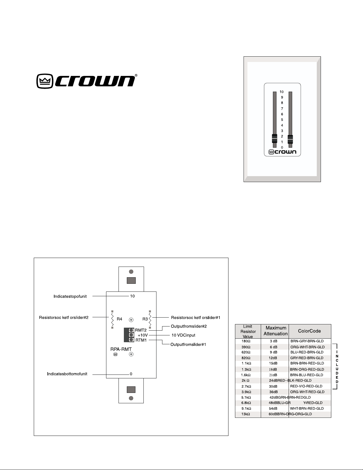
The resistor that you install determines how much attenuation is available. With no resistor installed, the
RPA-RMT will provide full attenuation. Thirty-two resistors with eight
different values are included with
each pair of RPA-RMTs. These eight
resistor values range from 390 to
2.7 K ohms and will satisfy most applications. Figure 2 shows the corresponding maximum attenuation for
several resistor values.
Fig. 1 RPA-RMT: Rear View
Once you know the attenuation requirements for your system, use Figure 2 to determine which resistors
are needed. An equation is provided
in the P.I.P.-RPA
to calculate other resistor values.
Fig. 2 Remote Control
Resistance/Voltage
Reference Manual
Page 2
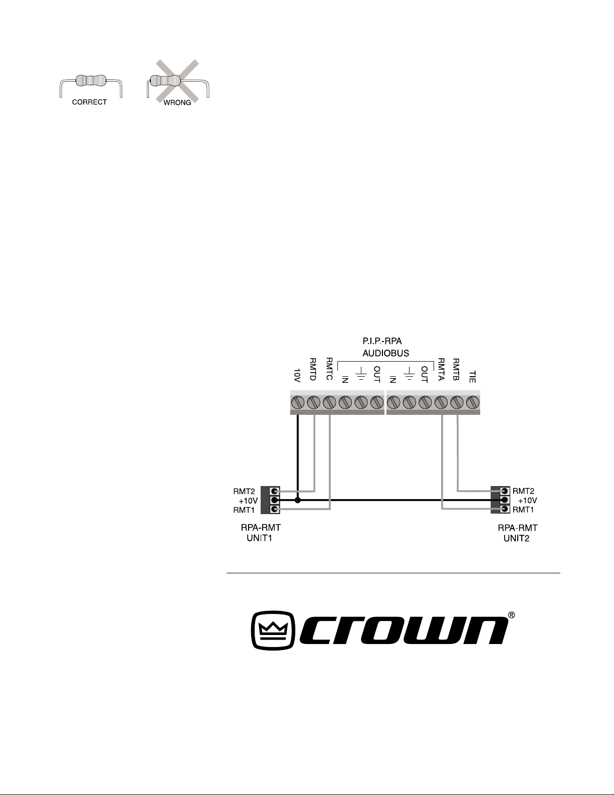
Fig. 3 Bending the
Resistor Leads
To install a resistor, trim the leads
leaving plenty to span the distance
between the sockets and enough to
insert into each socket. Bend the
leads as shown in Figure 3. Be sure
not to bend the leads near the body
of the resistor. Push the leads down
firmly into the sockets. That’s it.
Wiring
Each RPA-RMT has two slide potentiometers. They can be used to control any two of the four audio inputs on
the P.I.P.-RPA, or they can be ganged
to control more channels. When using two channels of one amplifier to
feed different rooms, the RPA-RMT
will often be wired to control inputs A
and B, or C and D (see Figure 4).
Here,
PIP
inputs A and B are set to
feed the amplifier’s channel 1, and C
and D are set to feed channel 2. This
wiring scheme allows each RPA-RMT
to control a separate room.
RPA to the other channels being controlled (see the P.I.P.-RPA
Manual
for more details).
Reference
Mounting
Mount the RPA-RMT as you would an
AC outlet. Do not mount it in a box
having hot AC! Also, be careful not to
mount it upside down. You can orient
the unit by rotating it until the number
10 on back is at the top and the
number 0 is at the bottom (see Figure
1). Line up the threaded holes in the
receptacle box with the square openings in the RPA-RMT and secure it
with the provided screws.
The RPA-RMT is designed to accept
“designer” series cover plates. Cover
plates are not included because the
provided stick-on labels allow considerable flexibility when choosing
colors to match different interiors.
Labels
Three labels are supplied, each with
a different color scheme: white background with brown print, ivory background with brown print and brown
background with ivory print. These
labels match industry standard colors and allow you to select cover
plates to match almost any interior.
Select a stick-on label and affix it to
the remote control faceplate. You can
use the opening in the cover plate as
a guide. Peel the backing and the
plastic front protector from the label
and affix it to the remote unit faceplate. The last step is to push on the
slider knobs.
If you need more information or further assistance, feel free to contact
Crown Technical Services at 219294-8200 or 1-800-342-6939.
The RPA-RMT does not receive any
audio signals. Instead, it receives
10 VDC supplied by the P.I.P.-RPA.
The voltages that return to the
PIP
control its VCAs (Voltage-Controlled
Amplifiers) which control the levels of
the corresponding audio inputs.
Connect the P.I.P.-RPA’s 10 V output
to the RPA-RMT’s +10 V input. Inside
the RPA-RMT, the 10 V signal is fed to
both potentiometers. In turn, the potentiometers control the voltages leaving through the RMT 1 and RMT 2
outputs. Connect these outputs to
any of the four remote inputs on the
P.I.P.-RPA labeled RMT A, B, C or D.
When connecting two remote control
units, run the DC output from the
P.I.P.-RPA in parallel to feed both DC
inputs on the remote units.
When ganging several channels on
one remote slider, run jumper wires
from the remote input on the P.I.P.-
Fig. 4 Wiring for Two RPA-RMTs
© 1997 by Crown International, Inc.
P.O. BOX 1000,Elkhart,IN 46515-1000 USA
(TEL)800-342-6939 OR 219-294-8000, (FAX)219-294-8329
Trademark Notice:
®
P.I.P.
are registered trademarks of Crown International, Inc.
™
PIP
is a trademark and
Crown
®
and
125240-1
9/97
 Loading...