

Page 1
RC
RC 5500 Series
AC Traction
Service & Parts Manual
Crown 2007 PF15343 3/07
Page 2

New Bremen, Ohio 45869 USA
H
Phone 419/629-2311
crown.com
ow to Order Service Parts
To obtain fast, efficient service when ordering repair parts for your Crown Material Handling Equipment, please
follow this simple procedure:
1. Address all orders to your local Crown dealer.
2. Specify model and serial number of truck, which is shown on the serial number plate.
3. List the quantity needed.
4. List the part number and description, as shown in this Service Manual.
5. Show billing and shipping address.
6. Suggest fastest routing.
Your authorized Crown dealer stocks a large number of standard service parts. In addition, he has a factory trained Service Department to serve you.
Our Local Crown Dealer Is
NAME
ADDRESS
CITY
STATE ZIP
TELEPHONE
The information in this manual is the latest available at the time of printing for the unit with which it was shipped.
Should there be any variation due to vendor changes or special options on your unit, contact your Crown dealer
or Crown at the above address.
Crown 1986 Printed in U.S.A.
PF7609 Rev. 4/01
Page 3

.
Page 4

TABLE OF CONTENTS
I
Page 5

Notes:
II
Page 6

TABLE OF CONTENTS
SAFETY PAGE
General Maintenance Instructions . . . . . . . . . . . . . . . . . . . . . . .3
Control of Hazardous Energy . . . . . . . . . . . . . . . . . . . . . . . . . . .5
Lockout/Tagout . . . . . . . . . . . . . . . . . . . . . . . . . . . . . . . . . . . . . 5
Battery . . . . . . . . . . . . . . . . . . . . . . . . . . . . . . . . . . . . . . . . . . . .5
Safety Rules . . . . . . . . . . . . . . . . . . . . . . . . . . . . . . . . . . . . 5
Battery Care . . . . . . . . . . . . . . . . . . . . . . . . . . . . . . . . . . . . . 5
Charging . . . . . . . . . . . . . . . . . . . . . . . . . . . . . . . . . . . . . . .5
Battery Removal . . . . . . . . . . . . . . . . . . . . . . . . . . . . . . . . . 6
Battery Installation . . . . . . . . . . . . . . . . . . . . . . . . . . . . . . . . 6
Lockout - Tagout . . . . . . . . . . . . . . . . . . . . . . . . . . . . . . . . .6
Brake Release Instructions . . . . . . . . . . . . . . . . . . . . . . . . . 7
Capacitance . . . . . . . . . . . . . . . . . . . . . . . . . . . . . . . . . . . . . . .8
Hydraulic . . . . . . . . . . . . . . . . . . . . . . . . . . . . . . . . . . . . . . . . . .8
Towing Truck . . . . . . . . . . . . . . . . . . . . . . . . . . . . . . . . . . . . . . .9
Towing by Pulling in
Power Unit First Direction . . . . . . . . . . . . . . . . . . . . . . . . .9
Towing by Pulling
in the Forks First Direction . . . . . . . . . . . . . . . . . . . . . . .10
Towing by Lifting Truck and
Pulling in Power Unit First Direction . . . . . . . . . . . . . . . . .10
Towing by Lifting Truck and
Pulling in the Forks First Direction . . . . . . . . . . . . . . . .10
Lifting and Blocking . . . . . . . . . . . . . . . . . . . . . . . . . . . . . . . . . 11
Mast . . . . . . . . . . . . . . . . . . . . . . . . . . . . . . . . . . . . . . . . . . . . 12
Blocking Masts . . . . . . . . . . . . . . . . . . . . . . . . . . . . . . . . . .12
Disconnecting Tilt Cylinder . . . . . . . . . . . . . . . . . . . . . . . . . . .14
Removing Mast . . . . . . . . . . . . . . . . . . . . . . . . . . . . . . . . . . . . 15
Cleaning of Material Handling Equipment . . . . . . . . . . . . . . . .17
Cleaning Methods . . . . . . . . . . . . . . . . . . . . . . . . . . . . . . . . . .17
TABLE OF CONTENTS
INTRODUCTION PAGE
Introduction . . . . . . . . . . . . . . . . . . . . . . . . . . . . . . . . . . . . . . . .21
Operation Instructions . . . . . . . . . . . . . . . . . . . . . . . . . . . . . . . 21
Operater Training . . . . . . . . . . . . . . . . . . . . . . . . . . . . . . . . . .21
Service Training . . . . . . . . . . . . . . . . . . . . . . . . . . . . . . . . . . . 21
Replacement Parts . . . . . . . . . . . . . . . . . . . . . . . . . . . . . . . . .21
LUBRICATION & ADJUSTMENT PAGE
Lubrication and Adjustment . . . . . . . . . . . . . . . . . . . . . . . . . . .27
Lubrication and Adjustment . . . . . . . . . . . . . . . . . . . . . . . . . . .33
Component Accessibility . . . . . . . . . . . . . . . . . . . . . . . . . . . . . 33
Lubrication . . . . . . . . . . . . . . . . . . . . . . . . . . . . . . . . . . . . . . .35
Componentry . . . . . . . . . . . . . . . . . . . . . . . . . . . . . . . . . . . . . . . 45
Access 1 . . . . . . . . . . . . . . . . . . . . . . . . . . . . . . . . . . . . . . . . .45
Access 2 . . . . . . . . . . . . . . . . . . . . . . . . . . . . . . . . . . . . . . . . .45
Access 3 . . . . . . . . . . . . . . . . . . . . . . . . . . . . . . . . . . . . . . . . .45
Access 7 . . . . . . . . . . . . . . . . . . . . . . . . . . . . . . . . . . . . . . . . .46
ALM1 . . . . . . . . . . . . . . . . . . . . . . . . . . . . . . . . . . . . . . . . . . . .46
ALM2 . . . . . . . . . . . . . . . . . . . . . . . . . . . . . . . . . . . . . . . . . . . .46
III
Page 7

TABLE OF CONTENTS
BRESL, BRESR . . . . . . . . . . . . . . . . . . . . . . . . . . . . . . . . . . . 46
BRKS . . . . . . . . . . . . . . . . . . . . . . . . . . . . . . . . . . . . . . . . . . . 47
BRK1 . . . . . . . . . . . . . . . . . . . . . . . . . . . . . . . . . . . . . . . . . . . 47
BRK2 . . . . . . . . . . . . . . . . . . . . . . . . . . . . . . . . . . . . . . . . . . . 47
CBVE . . . . . . . . . . . . . . . . . . . . . . . . . . . . . . . . . . . . . . . . . . . 48
CBVR . . . . . . . . . . . . . . . . . . . . . . . . . . . . . . . . . . . . . . . . . . . 48
CVR . . . . . . . . . . . . . . . . . . . . . . . . . . . . . . . . . . . . . . . . . . . . 49
DLS . . . . . . . . . . . . . . . . . . . . . . . . . . . . . . . . . . . . . . . . . . . . 49
DMS1, DMS2, DMS3 . . . . . . . . . . . . . . . . . . . . . . . . . . . . . . . 49
ECR1 . . . . . . . . . . . . . . . . . . . . . . . . . . . . . . . . . . . . . . . . . . . 50
ECR2 . . . . . . . . . . . . . . . . . . . . . . . . . . . . . . . . . . . . . . . . . . . 50
ECR3 . . . . . . . . . . . . . . . . . . . . . . . . . . . . . . . . . . . . . . . . . . . 50
ECR4 . . . . . . . . . . . . . . . . . . . . . . . . . . . . . . . . . . . . . . . . . . . 51
EDS . . . . . . . . . . . . . . . . . . . . . . . . . . . . . . . . . . . . . . . . . . . . 51
ENLS, ENSR . . . . . . . . . . . . . . . . . . . . . . . . . . . . . . . . . . . . . 52
FNS . . . . . . . . . . . . . . . . . . . . . . . . . . . . . . . . . . . . . . . . . . . . 52
FAN1 . . . . . . . . . . . . . . . . . . . . . . . . . . . . . . . . . . . . . . . . . . . 52
FAN2 . . . . . . . . . . . . . . . . . . . . . . . . . . . . . . . . . . . . . . . . . . . 53
FS . . . . . . . . . . . . . . . . . . . . . . . . . . . . . . . . . . . . . . . . . . . . . 53
FU1 . . . . . . . . . . . . . . . . . . . . . . . . . . . . . . . . . . . . . . . . . . . . 53
FU2 . . . . . . . . . . . . . . . . . . . . . . . . . . . . . . . . . . . . . . . . . . . . 54
FU3 . . . . . . . . . . . . . . . . . . . . . . . . . . . . . . . . . . . . . . . . . . . . 54
FU4 . . . . . . . . . . . . . . . . . . . . . . . . . . . . . . . . . . . . . . . . . . . . 54
FU5 . . . . . . . . . . . . . . . . . . . . . . . . . . . . . . . . . . . . . . . . . . . . 55
FU13/FU14 . . . . . . . . . . . . . . . . . . . . . . . . . . . . . . . . . . . . . . 55
HGTS1 . . . . . . . . . . . . . . . . . . . . . . . . . . . . . . . . . . . . . . . . . . 55
HGTS2 . . . . . . . . . . . . . . . . . . . . . . . . . . . . . . . . . . . . . . . . . . 56
HGTS3 . . . . . . . . . . . . . . . . . . . . . . . . . . . . . . . . . . . . . . . . . . 56
HGTS4 . . . . . . . . . . . . . . . . . . . . . . . . . . . . . . . . . . . . . . . . . . 56
HN1 . . . . . . . . . . . . . . . . . . . . . . . . . . . . . . . . . . . . . . . . . . . . 57
HNS . . . . . . . . . . . . . . . . . . . . . . . . . . . . . . . . . . . . . . . . . . . . 57
K1 . . . . . . . . . . . . . . . . . . . . . . . . . . . . . . . . . . . . . . . . . . . . . . 58
K2 . . . . . . . . . . . . . . . . . . . . . . . . . . . . . . . . . . . . . . . . . . . . . . 58
KYS . . . . . . . . . . . . . . . . . . . . . . . . . . . . . . . . . . . . . . . . . . . . 58
L . . . . . . . . . . . . . . . . . . . . . . . . . . . . . . . . . . . . . . . . . . . . . . . 59
LCV . . . . . . . . . . . . . . . . . . . . . . . . . . . . . . . . . . . . . . . . . . . . 59
LGT1, LGT2 . . . . . . . . . . . . . . . . . . . . . . . . . . . . . . . . . . . . . . 59
LGTS1 . . . . . . . . . . . . . . . . . . . . . . . . . . . . . . . . . . . . . . . . . . 60
LGT3 . . . . . . . . . . . . . . . . . . . . . . . . . . . . . . . . . . . . . . . . . . . 60
LGT4 . . . . . . . . . . . . . . . . . . . . . . . . . . . . . . . . . . . . . . . . . . . 60
M1 . . . . . . . . . . . . . . . . . . . . . . . . . . . . . . . . . . . . . . . . . . . . . 61
M2 . . . . . . . . . . . . . . . . . . . . . . . . . . . . . . . . . . . . . . . . . . . . . 61
M3 . . . . . . . . . . . . . . . . . . . . . . . . . . . . . . . . . . . . . . . . . . . . . 61
ORS . . . . . . . . . . . . . . . . . . . . . . . . . . . . . . . . . . . . . . . . . . . . 62
PCA . . . . . . . . . . . . . . . . . . . . . . . . . . . . . . . . . . . . . . . . . . . . 62
POT1 . . . . . . . . . . . . . . . . . . . . . . . . . . . . . . . . . . . . . . . . . . . 62
POT2 . . . . . . . . . . . . . . . . . . . . . . . . . . . . . . . . . . . . . . . . . . . 63
POT3 . . . . . . . . . . . . . . . . . . . . . . . . . . . . . . . . . . . . . . . . . . . 63
POT4 . . . . . . . . . . . . . . . . . . . . . . . . . . . . . . . . . . . . . . . . . . . 63
P . . . . . . . . . . . . . . . . . . . . . . . . . . . . . . . . . . . . . . . . . . . . . . . 64
PT1 . . . . . . . . . . . . . . . . . . . . . . . . . . . . . . . . . . . . . . . . . . . . 64
PRVA . . . . . . . . . . . . . . . . . . . . . . . . . . . . . . . . . . . . . . . . . . . 64
RPS1 . . . . . . . . . . . . . . . . . . . . . . . . . . . . . . . . . . . . . . . . . . . 65
RPS2 . . . . . . . . . . . . . . . . . . . . . . . . . . . . . . . . . . . . . . . . . . . 65
IV
Page 8

RS . . . . . . . . . . . . . . . . . . . . . . . . . . . . . . . . . . . . . . . . . . . . . .65
RVA . . . . . . . . . . . . . . . . . . . . . . . . . . . . . . . . . . . . . . . . . . . . . 66
RVM . . . . . . . . . . . . . . . . . . . . . . . . . . . . . . . . . . . . . . . . . . . .66
SSS . . . . . . . . . . . . . . . . . . . . . . . . . . . . . . . . . . . . . . . . . . . . .66
SPL . . . . . . . . . . . . . . . . . . . . . . . . . . . . . . . . . . . . . . . . . . . . . 67
SPA . . . . . . . . . . . . . . . . . . . . . . . . . . . . . . . . . . . . . . . . . . . . .67
SVTE . . . . . . . . . . . . . . . . . . . . . . . . . . . . . . . . . . . . . . . . . . . .67
SVTR . . . . . . . . . . . . . . . . . . . . . . . . . . . . . . . . . . . . . . . . . . .68
SVT . . . . . . . . . . . . . . . . . . . . . . . . . . . . . . . . . . . . . . . . . . . . .68
SVH . . . . . . . . . . . . . . . . . . . . . . . . . . . . . . . . . . . . . . . . . . . . . 68
SVBy . . . . . . . . . . . . . . . . . . . . . . . . . . . . . . . . . . . . . . . . . . . . 69
SVA1A . . . . . . . . . . . . . . . . . . . . . . . . . . . . . . . . . . . . . . . . . . . 69
SVA1B . . . . . . . . . . . . . . . . . . . . . . . . . . . . . . . . . . . . . . . . . . . 69
SVA2A . . . . . . . . . . . . . . . . . . . . . . . . . . . . . . . . . . . . . . . . . . . 70
SVA2B . . . . . . . . . . . . . . . . . . . . . . . . . . . . . . . . . . . . . . . . . . . 70
SVA3 . . . . . . . . . . . . . . . . . . . . . . . . . . . . . . . . . . . . . . . . . . . .70
TBS . . . . . . . . . . . . . . . . . . . . . . . . . . . . . . . . . . . . . . . . . . . . .70
TDS . . . . . . . . . . . . . . . . . . . . . . . . . . . . . . . . . . . . . . . . . . . . .71
TR1 . . . . . . . . . . . . . . . . . . . . . . . . . . . . . . . . . . . . . . . . . . . . . 71
TR2 . . . . . . . . . . . . . . . . . . . . . . . . . . . . . . . . . . . . . . . . . . . . . 71
TS1 . . . . . . . . . . . . . . . . . . . . . . . . . . . . . . . . . . . . . . . . . . . . .72
TS2 . . . . . . . . . . . . . . . . . . . . . . . . . . . . . . . . . . . . . . . . . . . . .72
TS3 . . . . . . . . . . . . . . . . . . . . . . . . . . . . . . . . . . . . . . . . . . . . .72
Metric Torque Values . . . . . . . . . . . . . . . . . . . . . . . . . . . . . . . . . 73
Grade . . . . . . . . . . . . . . . . . . . . . . . . . . . . . . . . . . . . . . . . . . .73
Torque Values . . . . . . . . . . . . . . . . . . . . . . . . . . . . . . . . . . . . . . .77
Grade . . . . . . . . . . . . . . . . . . . . . . . . . . . . . . . . . . . . . . . . . . .77
TABLE OF CONTENTS
HYDRAULIC PAGE
General Information . . . . . . . . . . . . . . . . . . . . . . . . . . . . . . . . . .81
Hydraulic Lines and Fittings . . . . . . . . . . . . . . . . . . . . . . . . . . 81
Reservoir . . . . . . . . . . . . . . . . . . . . . . . . . . . . . . . . . . . . . . . . .81
Filter . . . . . . . . . . . . . . . . . . . . . . . . . . . . . . . . . . . . . . . . . . . .81
Drift Test . . . . . . . . . . . . . . . . . . . . . . . . . . . . . . . . . . . . . . . . .81
Lift Drift Test . . . . . . . . . . . . . . . . . . . . . . . . . . . . . . . . . . . . . . 82
Tilt Drift Test . . . . . . . . . . . . . . . . . . . . . . . . . . . . . . . . . . . . . . 82
Steering Slip . . . . . . . . . . . . . . . . . . . . . . . . . . . . . . . . . . . . . .82
Freezer Preparation . . . . . . . . . . . . . . . . . . . . . . . . . . . . . . . .82
Circuit Operation . . . . . . . . . . . . . . . . . . . . . . . . . . . . . . . . . . . 82
Hydraulic Circuits . . . . . . . . . . . . . . . . . . . . . . . . . . . . . . . . . . . 84
Steering Circuit . . . . . . . . . . . . . . . . . . . . . . . . . . . . . . . . . . . .84
Hoist . . . . . . . . . . . . . . . . . . . . . . . . . . . . . . . . . . . . . . . . . . . .85
Lift Circuit . . . . . . . . . . . . . . . . . . . . . . . . . . . . . . . . . . . . . . . . 85
Lower Circuit . . . . . . . . . . . . . . . . . . . . . . . . . . . . . . . . . . . . . . 86
Tilt and Accessory Flow . . . . . . . . . . . . . . . . . . . . . . . . . . . . .87
Tilt . . . . . . . . . . . . . . . . . . . . . . . . . . . . . . . . . . . . . . . . . . . . . .87
Tilt Down Circuit . . . . . . . . . . . . . . . . . . . . . . . . . . . . . . . . . . .88
Tilt Back Circuit . . . . . . . . . . . . . . . . . . . . . . . . . . . . . . . . . . . . 89
Tilt Position Assist . . . . . . . . . . . . . . . . . . . . . . . . . . . . . . . . . .90
Sideshift - Left Circuit . . . . . . . . . . . . . . . . . . . . . . . . . . . . . . .90
Sideshift - Right Circuit . . . . . . . . . . . . . . . . . . . . . . . . . . . . . .91
Fourth Hydraulic Function (Second Accessory) . . . . . . . . . . . 91
Fifth Hydraulic Function (Third Accessory) . . . . . . . . . . . . . . . 91
V
Page 9

TABLE OF CONTENTS
Accessory Clamp Set-Up . . . . . . . . . . . . . . . . . . . . . . . . . . . . . 93
Attachment Setup - General . . . . . . . . . . . . . . . . . . . . . . . . . 93
Attachment Setup - Clamp . . . . . . . . . . . . . . . . . . . . . . . . . . . 93
Hydraulic Schematic Symbols . . . . . . . . . . . . . . . . . . . . . . . . . 97
Pump Maintenance . . . . . . . . . . . . . . . . . . . . . . . . . . . . . . . . . 101
General . . . . . . . . . . . . . . . . . . . . . . . . . . . . . . . . . . . . . . . . 101
Pump Disassembly . . . . . . . . . . . . . . . . . . . . . . . . . . . . . . . 101
Parts Inspection . . . . . . . . . . . . . . . . . . . . . . . . . . . . . . . . . . 101
Body . . . . . . . . . . . . . . . . . . . . . . . . . . . . . . . . . . . . . . . . . . . 101
Priority Valve . . . . . . . . . . . . . . . . . . . . . . . . . . . . . . . . . . . . 101
Pump Reassembly . . . . . . . . . . . . . . . . . . . . . . . . . . . . . . . . 102
Start Up Procedure . . . . . . . . . . . . . . . . . . . . . . . . . . . . . . . 102
DRIVE UNIT PAGE
Drive Unit . . . . . . . . . . . . . . . . . . . . . . . . . . . . . . . . . . . . . . . . . 107
Inspect Drive Unit . . . . . . . . . . . . . . . . . . . . . . . . . . . . . . . . . 107
Drive Unit Lubrication . . . . . . . . . . . . . . . . . . . . . . . . . . . . . . 107
Drive Tire Replacement . . . . . . . . . . . . . . . . . . . . . . . . . . . . 108
Traction Motor . . . . . . . . . . . . . . . . . . . . . . . . . . . . . . . . . . . 109
Traction Motor Removal . . . . . . . . . . . . . . . . . . . . . . . . . 109
Traction Motor Installation . . . . . . . . . . . . . . . . . . . . . . . . 109
Drive Unit Removal . . . . . . . . . . . . . . . . . . . . . . . . . . . . . . . 110
Drive Unit Installation . . . . . . . . . . . . . . . . . . . . . . . . . . . 110
Drive Unit Sub-Assembly Removal . . . . . . . . . . . . . . . . . . . .111
Drive Unit Gear Assembly Replacement/Installation . . . . . . 113
ELECTRICAL PAGE
Electrical . . . . . . . . . . . . . . . . . . . . . . . . . . . . . . . . . . . . . . . . . 117
Electrical System . . . . . . . . . . . . . . . . . . . . . . . . . . . . . . . . . . 121
Wiring Color Codes . . . . . . . . . . . . . . . . . . . . . . . . . . . . . . . 121
Power Cables . . . . . . . . . . . . . . . . . . . . . . . . . . . . . . . . . . . . 121
Switches . . . . . . . . . . . . . . . . . . . . . . . . . . . . . . . . . . . . . . . . 125
ACCESS 123...System . . . . . . . . . . . . . . . . . . . . . . . . . . . . . . 133
ACCESS 1 Display . . . . . . . . . . . . . . . . . . . . . . . . . . . . . . . 133
Operator Level . . . . . . . . . . . . . . . . . . . . . . . . . . . . . . . . . . . 133
Message Mode . . . . . . . . . . . . . . . . . . . . . . . . . . . . . . . . . . 134
Timer - Message Mode . . . . . . . . . . . . . . . . . . . . . . . . . . 134
Trip - Message Mode . . . . . . . . . . . . . . . . . . . . . . . . . . . 134
Bdi - Message Mode . . . . . . . . . . . . . . . . . . . . . . . . . . . . 134
Hours - Message Mode . . . . . . . . . . . . . . . . . . . . . . . . . 135
Odometer - Message Mode . . . . . . . . . . . . . . . . . . . . . . 135
Hour . . . . . . . . . . . . . . . . . . . . . . . . . . . . . . . . . . . . . . . . . . . 135
Pressure . . . . . . . . . . . . . . . . . . . . . . . . . . . . . . . . . . . . . . . . 135
Events . . . . . . . . . . . . . . . . . . . . . . . . . . . . . . . . . . . . . . . . . 135
Service . . . . . . . . . . . . . . . . . . . . . . . . . . . . . . . . . . . . . . . . . 136
Level 2 . . . . . . . . . . . . . . . . . . . . . . . . . . . . . . . . . . . . . . 136
Level 3 . . . . . . . . . . . . . . . . . . . . . . . . . . . . . . . . . . . . . . 136
Bleed Quick Disconnect . . . . . . . . . . . . . . . . . . . . . . . . . 136
Performance . . . . . . . . . . . . . . . . . . . . . . . . . . . . . . . . . . . . 137
Relief Pressure Setup . . . . . . . . . . . . . . . . . . . . . . . . . . . . . 137
VI
Page 10

Analyzer . . . . . . . . . . . . . . . . . . . . . . . . . . . . . . . . . . . . . . . .174
Analyzer Access . . . . . . . . . . . . . . . . . . . . . . . . . . . . . . .174
A1 Status . . . . . . . . . . . . . . . . . . . . . . . . . . . . . . . . . . . . . 174
A2 Inputs . . . . . . . . . . . . . . . . . . . . . . . . . . . . . . . . . . . . .175
A3 Outputs . . . . . . . . . . . . . . . . . . . . . . . . . . . . . . . . . . . .179
A4 Test Outputs . . . . . . . . . . . . . . . . . . . . . . . . . . . . . . . .181
Calibration . . . . . . . . . . . . . . . . . . . . . . . . . . . . . . . . . . . . . . .182
Features . . . . . . . . . . . . . . . . . . . . . . . . . . . . . . . . . . . . . . . .188
Hours . . . . . . . . . . . . . . . . . . . . . . . . . . . . . . . . . . . . . . . . . .192
Hour Access . . . . . . . . . . . . . . . . . . . . . . . . . . . . . . . . . . 192
Events . . . . . . . . . . . . . . . . . . . . . . . . . . . . . . . . . . . . . . . . . .192
Performance . . . . . . . . . . . . . . . . . . . . . . . . . . . . . . . . . . . . .193
Utilities . . . . . . . . . . . . . . . . . . . . . . . . . . . . . . . . . . . . . . . . .196
Control Modules . . . . . . . . . . . . . . . . . . . . . . . . . . . . . . . . . . . . 197
Traction Drive Module . . . . . . . . . . . . . . . . . . . . . . . . . . . . . .197
Basics of System Operation . . . . . . . . . . . . . . . . . . . . . . . . . 197
Control Circuit Operation . . . . . . . . . . . . . . . . . . . . . . . . . . . 197
Power Circuit Operation . . . . . . . . . . . . . . . . . . . . . . . . . . . . 198
Hydraulic Control Module - AC/DC . . . . . . . . . . . . . . . . . . . . 199
Basics of System Operation . . . . . . . . . . . . . . . . . . . . . . . . . 199
Accessory Control Module . . . . . . . . . . . . . . . . . . . . . . . . . .199
Basics of System Operation . . . . . . . . . . . . . . . . . . . . . . . . . 199
Contactor . . . . . . . . . . . . . . . . . . . . . . . . . . . . . . . . . . . . . . . . .201
Battery . . . . . . . . . . . . . . . . . . . . . . . . . . . . . . . . . . . . . . . . . . . . 203
Safety Rules . . . . . . . . . . . . . . . . . . . . . . . . . . . . . . . . . . . . .203
Checking . . . . . . . . . . . . . . . . . . . . . . . . . . . . . . . . . . . . . . . . 203
Battery Care . . . . . . . . . . . . . . . . . . . . . . . . . . . . . . . . . . . . . 204
Charging . . . . . . . . . . . . . . . . . . . . . . . . . . . . . . . . . . . . . . . .204
Battery Cleaning . . . . . . . . . . . . . . . . . . . . . . . . . . . . . . . . . . 205
Troubleshooting . . . . . . . . . . . . . . . . . . . . . . . . . . . . . . . . . .205
Battery Removal . . . . . . . . . . . . . . . . . . . . . . . . . . . . . . . . . .205
Battery Installation . . . . . . . . . . . . . . . . . . . . . . . . . . . . . . . .207
Motors . . . . . . . . . . . . . . . . . . . . . . . . . . . . . . . . . . . . . . . . . . . .209
Pump Motor and Brush Inspection . . . . . . . . . . . . . . . . . . . .209
Event Codes . . . . . . . . . . . . . . . . . . . . . . . . . . . . . . . . . . . . . . . 211
Capacitance . . . . . . . . . . . . . . . . . . . . . . . . . . . . . . . . . . . . . 212
Event Code 100 . . . . . . . . . . . . . . . . . . . . . . . . . . . . . . . . . . . . 214
Event Code 101 . . . . . . . . . . . . . . . . . . . . . . . . . . . . . . . . . . . . 214
Event Code 102 . . . . . . . . . . . . . . . . . . . . . . . . . . . . . . . . . . . . 215
Event Code 103 . . . . . . . . . . . . . . . . . . . . . . . . . . . . . . . . . . . . 215
Event Code 104 . . . . . . . . . . . . . . . . . . . . . . . . . . . . . . . . . . . . 216
Event Code 105 . . . . . . . . . . . . . . . . . . . . . . . . . . . . . . . . . . . . 216
Event Code 106 . . . . . . . . . . . . . . . . . . . . . . . . . . . . . . . . . . . . 217
Event Code 107 . . . . . . . . . . . . . . . . . . . . . . . . . . . . . . . . . . . . 218
Event Code 108 . . . . . . . . . . . . . . . . . . . . . . . . . . . . . . . . . . . . 219
Event Code 109 . . . . . . . . . . . . . . . . . . . . . . . . . . . . . . . . . . . . 220
Event Code 110 . . . . . . . . . . . . . . . . . . . . . . . . . . . . . . . . . . . . 221
Event Code 111 . . . . . . . . . . . . . . . . . . . . . . . . . . . . . . . . . . . . .222
Event Code 112 . . . . . . . . . . . . . . . . . . . . . . . . . . . . . . . . . . . . 223
Event Code 113 . . . . . . . . . . . . . . . . . . . . . . . . . . . . . . . . . . . . 224
Event Code 114 . . . . . . . . . . . . . . . . . . . . . . . . . . . . . . . . . . . . 225
Event Code 199 . . . . . . . . . . . . . . . . . . . . . . . . . . . . . . . . . . . . 225
Event Code 200 . . . . . . . . . . . . . . . . . . . . . . . . . . . . . . . . . . . . 226
Event Code 201 . . . . . . . . . . . . . . . . . . . . . . . . . . . . . . . . . . . . 227
TABLE OF CONTENTS
VII
Page 11

TABLE OF CONTENTS
Event Code 202 . . . . . . . . . . . . . . . . . . . . . . . . . . . . . . . . . . . . 228
Event Code 202 . . . . . . . . . . . . . . . . . . . . . . . . . . . . . . . . . . . . 228
Event Code 203 . . . . . . . . . . . . . . . . . . . . . . . . . . . . . . . . . . . . 230
Event Code 203 . . . . . . . . . . . . . . . . . . . . . . . . . . . . . . . . . . . . 231
Event Code 204 . . . . . . . . . . . . . . . . . . . . . . . . . . . . . . . . . . . . 232
Event Code 205 . . . . . . . . . . . . . . . . . . . . . . . . . . . . . . . . . . . . 233
Event Code 206 . . . . . . . . . . . . . . . . . . . . . . . . . . . . . . . . . . . . 234
Event Code 207 . . . . . . . . . . . . . . . . . . . . . . . . . . . . . . . . . . . . 236
Event Code 208 . . . . . . . . . . . . . . . . . . . . . . . . . . . . . . . . . . . . 237
Event Code 209 . . . . . . . . . . . . . . . . . . . . . . . . . . . . . . . . . . . . 238
Event Code 212 . . . . . . . . . . . . . . . . . . . . . . . . . . . . . . . . . . . . 238
Event Code 213 . . . . . . . . . . . . . . . . . . . . . . . . . . . . . . . . . . . . 239
Event Code 214 . . . . . . . . . . . . . . . . . . . . . . . . . . . . . . . . . . . . 240
Event Code 215 . . . . . . . . . . . . . . . . . . . . . . . . . . . . . . . . . . . . 240
Event Code 216 . . . . . . . . . . . . . . . . . . . . . . . . . . . . . . . . . . . . 240
Event Code 217 . . . . . . . . . . . . . . . . . . . . . . . . . . . . . . . . . . . . 241
Event Code 218 . . . . . . . . . . . . . . . . . . . . . . . . . . . . . . . . . . . . 242
Event Code 219 . . . . . . . . . . . . . . . . . . . . . . . . . . . . . . . . . . . . 243
Event Code 220 . . . . . . . . . . . . . . . . . . . . . . . . . . . . . . . . . . . . 243
Event Code 221 . . . . . . . . . . . . . . . . . . . . . . . . . . . . . . . . . . . . 244
Event Code 222 . . . . . . . . . . . . . . . . . . . . . . . . . . . . . . . . . . . . 244
Event Code 223 . . . . . . . . . . . . . . . . . . . . . . . . . . . . . . . . . . . . 244
Event Code 224 . . . . . . . . . . . . . . . . . . . . . . . . . . . . . . . . . . . . 245
Event Code 300 . . . . . . . . . . . . . . . . . . . . . . . . . . . . . . . . . . . . 246
Event Code 301 . . . . . . . . . . . . . . . . . . . . . . . . . . . . . . . . . . . . 247
Event Code 302 . . . . . . . . . . . . . . . . . . . . . . . . . . . . . . . . . . . . 248
Event Code 303 . . . . . . . . . . . . . . . . . . . . . . . . . . . . . . . . . . . . 249
Event Code 304 . . . . . . . . . . . . . . . . . . . . . . . . . . . . . . . . . . . . 250
Event Code 305 . . . . . . . . . . . . . . . . . . . . . . . . . . . . . . . . . . . . 250
Event Code 306 . . . . . . . . . . . . . . . . . . . . . . . . . . . . . . . . . . . . 251
Event Code 307 . . . . . . . . . . . . . . . . . . . . . . . . . . . . . . . . . . . . 251
Event Code 308 . . . . . . . . . . . . . . . . . . . . . . . . . . . . . . . . . . . . 252
Event Code 309 . . . . . . . . . . . . . . . . . . . . . . . . . . . . . . . . . . . . 252
Event Code 310 . . . . . . . . . . . . . . . . . . . . . . . . . . . . . . . . . . . . 252
Event Code 311-313 . . . . . . . . . . . . . . . . . . . . . . . . . . . . . . . . 253
Event Code 314 . . . . . . . . . . . . . . . . . . . . . . . . . . . . . . . . . . . . 254
Event Code 315 . . . . . . . . . . . . . . . . . . . . . . . . . . . . . . . . . . . . 255
Event Code 316 . . . . . . . . . . . . . . . . . . . . . . . . . . . . . . . . . . . . 255
Event Code 318 . . . . . . . . . . . . . . . . . . . . . . . . . . . . . . . . . . . . 256
Event Code 319 . . . . . . . . . . . . . . . . . . . . . . . . . . . . . . . . . . . . 257
Event Code 399 . . . . . . . . . . . . . . . . . . . . . . . . . . . . . . . . . . . . 258
Event Code 700 . . . . . . . . . . . . . . . . . . . . . . . . . . . . . . . . . . . . 259
Event Code 701 . . . . . . . . . . . . . . . . . . . . . . . . . . . . . . . . . . . . 259
Event Code 702 . . . . . . . . . . . . . . . . . . . . . . . . . . . . . . . . . . . . 260
Event Code 703 . . . . . . . . . . . . . . . . . . . . . . . . . . . . . . . . . . . . 261
Event Code 704 . . . . . . . . . . . . . . . . . . . . . . . . . . . . . . . . . . . . 262
Event Code 705 . . . . . . . . . . . . . . . . . . . . . . . . . . . . . . . . . . . . 263
Event Code 706 . . . . . . . . . . . . . . . . . . . . . . . . . . . . . . . . . . . . 264
Event Code 707 . . . . . . . . . . . . . . . . . . . . . . . . . . . . . . . . . . . . 265
Event Code 708 . . . . . . . . . . . . . . . . . . . . . . . . . . . . . . . . . . . . 266
Event Code 709 . . . . . . . . . . . . . . . . . . . . . . . . . . . . . . . . . . . . 267
Event Code 710 . . . . . . . . . . . . . . . . . . . . . . . . . . . . . . . . . . . . 268
Event Code 711 . . . . . . . . . . . . . . . . . . . . . . . . . . . . . . . . . . . . 269
Event Code 712 . . . . . . . . . . . . . . . . . . . . . . . . . . . . . . . . . . . . 269
VIII
Page 12

Event Code 713 . . . . . . . . . . . . . . . . . . . . . . . . . . . . . . . . . . . . 270
Event Code 714 . . . . . . . . . . . . . . . . . . . . . . . . . . . . . . . . . . . . 270
Event Code 715 . . . . . . . . . . . . . . . . . . . . . . . . . . . . . . . . . . . . 271
Event Code 716 . . . . . . . . . . . . . . . . . . . . . . . . . . . . . . . . . . . . 271
Event Code 717 . . . . . . . . . . . . . . . . . . . . . . . . . . . . . . . . . . . . 272
Event Code 718 . . . . . . . . . . . . . . . . . . . . . . . . . . . . . . . . . . . . 272
Event Code 719 . . . . . . . . . . . . . . . . . . . . . . . . . . . . . . . . . . . . 273
Event Code 720 . . . . . . . . . . . . . . . . . . . . . . . . . . . . . . . . . . . . 273
Event Code 721 . . . . . . . . . . . . . . . . . . . . . . . . . . . . . . . . . . . . 274
Event Code 722 . . . . . . . . . . . . . . . . . . . . . . . . . . . . . . . . . . . . 275
Event Code 723 . . . . . . . . . . . . . . . . . . . . . . . . . . . . . . . . . . . . 276
Event Code 724 . . . . . . . . . . . . . . . . . . . . . . . . . . . . . . . . . . . . 277
Event Code 726 . . . . . . . . . . . . . . . . . . . . . . . . . . . . . . . . . . . . 278
Event Code 727 . . . . . . . . . . . . . . . . . . . . . . . . . . . . . . . . . . . . 278
Event Code 728 . . . . . . . . . . . . . . . . . . . . . . . . . . . . . . . . . . . . 279
Event Code 729 . . . . . . . . . . . . . . . . . . . . . . . . . . . . . . . . . . . . 280
Event Code 730 . . . . . . . . . . . . . . . . . . . . . . . . . . . . . . . . . . . . 281
Event Code 731 . . . . . . . . . . . . . . . . . . . . . . . . . . . . . . . . . . . . 282
Event Code 732 . . . . . . . . . . . . . . . . . . . . . . . . . . . . . . . . . . . . 282
Event Code 733 . . . . . . . . . . . . . . . . . . . . . . . . . . . . . . . . . . . . 283
Event Code 734 . . . . . . . . . . . . . . . . . . . . . . . . . . . . . . . . . . . . 284
Event Code 735 . . . . . . . . . . . . . . . . . . . . . . . . . . . . . . . . . . . . 284
Event Code 736 . . . . . . . . . . . . . . . . . . . . . . . . . . . . . . . . . . . . 285
Event Code 737 . . . . . . . . . . . . . . . . . . . . . . . . . . . . . . . . . . . . 286
Event Code 738 . . . . . . . . . . . . . . . . . . . . . . . . . . . . . . . . . . . . 286
Event Code 739 . . . . . . . . . . . . . . . . . . . . . . . . . . . . . . . . . . . . 286
Event Code 740 . . . . . . . . . . . . . . . . . . . . . . . . . . . . . . . . . . . . 287
Event Code 741 . . . . . . . . . . . . . . . . . . . . . . . . . . . . . . . . . . . . 288
Event Code 742 . . . . . . . . . . . . . . . . . . . . . . . . . . . . . . . . . . . . 288
Event Code 743 . . . . . . . . . . . . . . . . . . . . . . . . . . . . . . . . . . . . 288
Event Code 744 . . . . . . . . . . . . . . . . . . . . . . . . . . . . . . . . . . . . 288
Event Code 745 . . . . . . . . . . . . . . . . . . . . . . . . . . . . . . . . . . . . 290
Event Code 746 . . . . . . . . . . . . . . . . . . . . . . . . . . . . . . . . . . . . 292
Event Code 747 . . . . . . . . . . . . . . . . . . . . . . . . . . . . . . . . . . . . 293
Event Code 748 . . . . . . . . . . . . . . . . . . . . . . . . . . . . . . . . . . . . 293
Event Code 749 . . . . . . . . . . . . . . . . . . . . . . . . . . . . . . . . . . . . 294
Event Code 750 . . . . . . . . . . . . . . . . . . . . . . . . . . . . . . . . . . . . 294
Event Code 751 . . . . . . . . . . . . . . . . . . . . . . . . . . . . . . . . . . . . 295
Event Code 752 . . . . . . . . . . . . . . . . . . . . . . . . . . . . . . . . . . . . 295
Event Code 753 . . . . . . . . . . . . . . . . . . . . . . . . . . . . . . . . . . . . 295
Event Code 754 . . . . . . . . . . . . . . . . . . . . . . . . . . . . . . . . . . . . 295
Event Code 755 . . . . . . . . . . . . . . . . . . . . . . . . . . . . . . . . . . . . 295
Event Code 799 . . . . . . . . . . . . . . . . . . . . . . . . . . . . . . . . . . . . 295
TABLE OF CONTENTS
IX
Page 13

TABLE OF CONTENTS
BRAKE PAGE
Brake . . . . . . . . . . . . . . . . . . . . . . . . . . . . . . . . . . . . . . . . . . . . 299
Service Brake . . . . . . . . . . . . . . . . . . . . . . . . . . . . . . . . . . . . 299
Plugging Distance . . . . . . . . . . . . . . . . . . . . . . . . . . . . . . . . 299
Service Brake . . . . . . . . . . . . . . . . . . . . . . . . . . . . . . . . . . . . 300
Stopping Distance . . . . . . . . . . . . . . . . . . . . . . . . . . . . . . 300
Parking Brake Check . . . . . . . . . . . . . . . . . . . . . . . . . . . . . . 300
Electric Parking Brake Release Procedures . . . . . . . . . . . . 301
Releasing Parking Brake Using Operator Display . . . . . . . . 301
Releasing Parking Brake Using Truck Battery . . . . . . . . . . . 302
Releasing Parking Brake Using External Power Source . . . 302
Brake Switch Adjustment (BRKS) . . . . . . . . . . . . . . . . . . . . 303
Parking Brake Removal . . . . . . . . . . . . . . . . . . . . . . . . . . . . 303
STEERING PAGE
Steering . . . . . . . . . . . . . . . . . . . . . . . . . . . . . . . . . . . . . . . . . . 309
Hydrostatic Steering Unit . . . . . . . . . . . . . . . . . . . . . . . . . . . 309
Forward and Reverse Steering . . . . . . . . . . . . . . . . . . . . . . 309
Steer Tire . . . . . . . . . . . . . . . . . . . . . . . . . . . . . . . . . . . . . . . 309
Steer Command Assembly . . . . . . . . . . . . . . . . . . . . . . . . . 310
Housing to Yoke Assembly . . . . . . . . . . . . . . . . . . . . . . . . . 311
Steer Motor to Axle Housing Assembly . . . . . . . . . . . . . . . . 312
Wheel Assemblies to Steer Axle (Metallic Shield) . . . . . . . . 313
Wheel Assemblies to Steel Axle (Oil Seal) . . . . . . . . . . . . . 314
Hydraulic Steer Motor . . . . . . . . . . . . . . . . . . . . . . . . . . . . . . . 315
Disassembly . . . . . . . . . . . . . . . . . . . . . . . . . . . . . . . . . . . . . 315
Steer Motor Assembly . . . . . . . . . . . . . . . . . . . . . . . . . . . . . 316
Motor Timing . . . . . . . . . . . . . . . . . . . . . . . . . . . . . . . . . . 317
LIFTING MECHANISM PAGE
Mast . . . . . . . . . . . . . . . . . . . . . . . . . . . . . . . . . . . . . . . . . . . . . 321
Torque Requirements . . . . . . . . . . . . . . . . . . . . . . . . . . . . . . 321
Fork Adjustments . . . . . . . . . . . . . . . . . . . . . . . . . . . . . . . . . 321
Mast Flaking . . . . . . . . . . . . . . . . . . . . . . . . . . . . . . . . . . . . . 321
TT (Triple Telescopic Full Free Lift) Mast . . . . . . . . . . . . . . . 321
Mast Testing (Assembled) . . . . . . . . . . . . . . . . . . . . . . . . . . 322
Mast Inspection . . . . . . . . . . . . . . . . . . . . . . . . . . . . . . . . . . 322
Mast Disassembly . . . . . . . . . . . . . . . . . . . . . . . . . . . . . . . . 323
Removal From Power Unit . . . . . . . . . . . . . . . . . . . . . . . . . . 324
Mast Reassembly . . . . . . . . . . . . . . . . . . . . . . . . . . . . . . . . 325
Quad (Four Stage) Mast . . . . . . . . . . . . . . . . . . . . . . . . . . . 328
Mast Flaking . . . . . . . . . . . . . . . . . . . . . . . . . . . . . . . . . . . . . 328
Mast Testing (Assembled) . . . . . . . . . . . . . . . . . . . . . . . . . . 328
Mast Inspection . . . . . . . . . . . . . . . . . . . . . . . . . . . . . . . . . . 329
Mast Removal . . . . . . . . . . . . . . . . . . . . . . . . . . . . . . . . . . . 329
Carriage Removal . . . . . . . . . . . . . . . . . . . . . . . . . . . . . . . . 330
Carriage Inspection . . . . . . . . . . . . . . . . . . . . . . . . . . . . . . . 330
Lift Chain Tension . . . . . . . . . . . . . . . . . . . . . . . . . . . . . . . . 330
X
Page 14

Lift Chains . . . . . . . . . . . . . . . . . . . . . . . . . . . . . . . . . . . . . . . . .333
Inspection . . . . . . . . . . . . . . . . . . . . . . . . . . . . . . . . . . . . . . .333
Wear . . . . . . . . . . . . . . . . . . . . . . . . . . . . . . . . . . . . . . . .333
Rust and Corrosion . . . . . . . . . . . . . . . . . . . . . . . . . . . . .334
Cracked Plates . . . . . . . . . . . . . . . . . . . . . . . . . . . . . . . .334
Tight Joints . . . . . . . . . . . . . . . . . . . . . . . . . . . . . . . . . . . . 335
Protruding or Turned Pins . . . . . . . . . . . . . . . . . . . . . . . .335
Chain Side Wear . . . . . . . . . . . . . . . . . . . . . . . . . . . . . . .335
Lift Chain Lubrication . . . . . . . . . . . . . . . . . . . . . . . . . . . . . .336
Lift Chain Replacement . . . . . . . . . . . . . . . . . . . . . . . . . . . . . 336
Chain Anchors and Pulleys . . . . . . . . . . . . . . . . . . . . . . . 337
Leaf Chain Disconnect . . . . . . . . . . . . . . . . . . . . . . . . . . .337
Disconnect Procedures: . . . . . . . . . . . . . . . . . . . . . . . . . .337
Fork Inspection . . . . . . . . . . . . . . . . . . . . . . . . . . . . . . . . . . . . 339
Abrasion . . . . . . . . . . . . . . . . . . . . . . . . . . . . . . . . . . . . . . . .339
Overloading . . . . . . . . . . . . . . . . . . . . . . . . . . . . . . . . . . . . . .341
Fatigue . . . . . . . . . . . . . . . . . . . . . . . . . . . . . . . . . . . . . . . . . 342
Bent or Twisted Forks . . . . . . . . . . . . . . . . . . . . . . . . . . . . . . 342
Hanger . . . . . . . . . . . . . . . . . . . . . . . . . . . . . . . . . . . . . . . . .343
TABLE OF CONTENTS
CYLINDERS PAGE
Cylinders . . . . . . . . . . . . . . . . . . . . . . . . . . . . . . . . . . . . . . . . . . 347
Mast Cylinder . . . . . . . . . . . . . . . . . . . . . . . . . . . . . . . . . . . . 348
Mast Cylinder Inspection . . . . . . . . . . . . . . . . . . . . . . . . .349
Mast Cylinder Disassembly . . . . . . . . . . . . . . . . . . . . . . . 349
Mast Cylinder Repair . . . . . . . . . . . . . . . . . . . . . . . . . . . .349
Mast Cylinder Reassembly . . . . . . . . . . . . . . . . . . . . . . .351
Mast Cylinder Bleeding and Flushing Procedures . . . . . .351
Mast Cylinder Bleeding . . . . . . . . . . . . . . . . . . . . . . . . . . 352
Mast Cylinder Flushing . . . . . . . . . . . . . . . . . . . . . . . . . .352
Carriage Cylinder . . . . . . . . . . . . . . . . . . . . . . . . . . . . . . . . .353
Inspection . . . . . . . . . . . . . . . . . . . . . . . . . . . . . . . . . . . .353
Carriage Cylinder Disassembly . . . . . . . . . . . . . . . . . . . . 354
Carriage Cylinder Repair . . . . . . . . . . . . . . . . . . . . . . . . .354
Carriage Cylinder Reassembly . . . . . . . . . . . . . . . . . . . .356
Carriage Cylinder Bleeding and Flushing Procedures . . . 356
Carriage Cylinder Bleeding . . . . . . . . . . . . . . . . . . . . . . . 356
Carriage Cylinder Flushing . . . . . . . . . . . . . . . . . . . . . . .356
Tilt Cylinder . . . . . . . . . . . . . . . . . . . . . . . . . . . . . . . . . . . . . . 357
Tilt Cylinder Inspection . . . . . . . . . . . . . . . . . . . . . . . . . . .357
Tilt Cylinder Disassembly . . . . . . . . . . . . . . . . . . . . . . . . .358
Rod Disassembly . . . . . . . . . . . . . . . . . . . . . . . . . . . . . . .358
Tilt Cylinder Repair . . . . . . . . . . . . . . . . . . . . . . . . . . . . . 358
Tilt Cylinder and Rod Reassembly . . . . . . . . . . . . . . . . . .358
Tilt Cylinder Adjustment . . . . . . . . . . . . . . . . . . . . . . . . . .359
Tilt Cylinder Shimming . . . . . . . . . . . . . . . . . . . . . . . . . . .359
Tilt Cylinder Bleeding and Flushing Procedures . . . . . . .360
Tilt Cylinder Bleeding and Flushing . . . . . . . . . . . . . . . . .361
Sideshifter Cylinder . . . . . . . . . . . . . . . . . . . . . . . . . . . . . . . . . 363
Sideshifter Cylinder Inspection . . . . . . . . . . . . . . . . . . . . . . . 363
Sideshifter Cylinder Removal . . . . . . . . . . . . . . . . . . . . . . . . 364
Sideshifter Cylinder Disassembly . . . . . . . . . . . . . . . . . . . . . 365
Sideshifter Cylinder Reassembly . . . . . . . . . . . . . . . . . . . . . 366
XI
Page 15

TABLE OF CONTENTS
PLATFORM PAGE
Sideshifter . . . . . . . . . . . . . . . . . . . . . . . . . . . . . . . . . . . . . . . . 369
Sideshifter Inspection . . . . . . . . . . . . . . . . . . . . . . . . . . . . . . 369
Sideshifter Removal . . . . . . . . . . . . . . . . . . . . . . . . . . . . . . . 370
Sideshifter Installation . . . . . . . . . . . . . . . . . . . . . . . . . . . . . 371
Bearings . . . . . . . . . . . . . . . . . . . . . . . . . . . . . . . . . . . . . . . . 373
Bearing Lubrication . . . . . . . . . . . . . . . . . . . . . . . . . . . . . 373
Bearing Service . . . . . . . . . . . . . . . . . . . . . . . . . . . . . . . 373
Troubleshooting . . . . . . . . . . . . . . . . . . . . . . . . . . . . . . . . . . 375
Supply Circuit Test . . . . . . . . . . . . . . . . . . . . . . . . . . . . . . . . 375
Sideshift Circuit Test . . . . . . . . . . . . . . . . . . . . . . . . . . . . . . 376
GLOSSARY PAGE
Glossary . . . . . . . . . . . . . . . . . . . . . . . . . . . . . . . . . . . . . . . . . . 379
WIRING DIAGRAMS PAGE
Introduction to Diagram Usage . . . . . . . . . . . . . . . . . . . . . . . 391
Schematic . . . . . . . . . . . . . . . . . . . . . . . . . . . . . . . . . . . . . . 391
Pictorials . . . . . . . . . . . . . . . . . . . . . . . . . . . . . . . . . . . . . . . 391
Electrical Diagrams Index . . . . . . . . . . . . . . . . . . . . . . . . . . . 393
Electrical Schematic - AC Lift . . . . . . . . . . . . . . . . . . . . . . . . 394
Electrical Schematic - DC Lift . . . . . . . . . . . . . . . . . . . . . . . . 395
Distribution Panel . . . . . . . . . . . . . . . . . . . . . . . . . . . . . . . . . . 396
Display Module . . . . . . . . . . . . . . . . . . . . . . . . . . . . . . . . . . . . 397
Multi-Task Handle . . . . . . . . . . . . . . . . . . . . . . . . . . . . . . . . . . 398
Accessory Control Module . . . . . . . . . . . . . . . . . . . . . . . . . . 399
Traction Control Module . . . . . . . . . . . . . . . . . . . . . . . . . . . . 400
Hydraulic Control Module - AC Lift . . . . . . . . . . . . . . . . . . . . 401
Hydraulic Control Module - DC Lift . . . . . . . . . . . . . . . . . . . . 402
Motors and Brakes . . . . . . . . . . . . . . . . . . . . . . . . . . . . . . . . . 403
Console and Overhead Guard . . . . . . . . . . . . . . . . . . . . . . . . 404
Floorboard . . . . . . . . . . . . . . . . . . . . . . . . . . . . . . . . . . . . . . . . 405
Hydraulics, Height & Load Sense . . . . . . . . . . . . . . . . . . . . . 406
Freezer Condition . . . . . . . . . . . . . . . . . . . . . . . . . . . . . . . . . . 407
Power Cables - AC Lift (ANSI Trucks) . . . . . . . . . . . . . . . . . . 408
Power Cable - AC Lift w/Rapid Charge . . . . . . . . . . . . . . . . . 409
Power Cable - AC Lift (Euro Trucks) . . . . . . . . . . . . . . . . . . . 410
Power Cables - DC Lift (ANSI Trucks) . . . . . . . . . . . . . . . . . . 411
Power Cable - DC Lift w/Rapid Charge . . . . . . . . . . . . . . . . . 412
Power Cable - DC Lift (Euro Trucks) . . . . . . . . . . . . . . . . . . . 413
InfoLink . . . . . . . . . . . . . . . . . . . . . . . . . . . . . . . . . . . . . . . . . . 414
Wire Harnesses . . . . . . . . . . . . . . . . . . . . . . . . . . . . . . . . . . . . 415
HYDRAULIC SCHEMATIC PAGE
Entire Truck . . . . . . . . . . . . . . . . . . . . . . . . . . . . . . . . . . . . . . . 419
XII
Page 16

POWER UNIT PARTS PAGE
Power Unit . . . . . . . . . . . . . . . . . . . . . . . . . . . . . . . . . . . . . . . . 422
Armrest . . . . . . . . . . . . . . . . . . . . . . . . . . . . . . . . . . . . . . . . . . . 430
Suspended Floorboard . . . . . . . . . . . . . . . . . . . . . . . . . . . . . .434
FlexRide Suspension . . . . . . . . . . . . . . . . . . . . . . . . . . . . . . . .438
Entry Bar . . . . . . . . . . . . . . . . . . . . . . . . . . . . . . . . . . . . . . . . . . 444
Counterweight . . . . . . . . . . . . . . . . . . . . . . . . . . . . . . . . . . . . .446
Overhead Guard . . . . . . . . . . . . . . . . . . . . . . . . . . . . . . . . . . . .448
Battery Retainers, Spacers, Rollers . . . . . . . . . . . . . . . . . . . .454
HYDRAULIC PARTS PAGE
Reservoir . . . . . . . . . . . . . . . . . . . . . . . . . . . . . . . . . . . . . . . . . 458
Plumbing . . . . . . . . . . . . . . . . . . . . . . . . . . . . . . . . . . . . . . . . . . 460
Mast Plumbing - TT . . . . . . . . . . . . . . . . . . . . . . . . . . . . . . . . .464
Mast Plumbing - Quad . . . . . . . . . . . . . . . . . . . . . . . . . . . . . . . 466
DC Lift Pump . . . . . . . . . . . . . . . . . . . . . . . . . . . . . . . . . . . . . .474
Pump Motor - AC . . . . . . . . . . . . . . . . . . . . . . . . . . . . . . . . . . . 476
Pump Motor - DC . . . . . . . . . . . . . . . . . . . . . . . . . . . . . . . . . . . 478
Pump Motor - AC “EE” . . . . . . . . . . . . . . . . . . . . . . . . . . . . . . 480
Valve Assembly 1 Low Flow Accessory . . . . . . . . . . . . . . . . 482
Valve Assembly W/2 High Flow Accessories . . . . . . . . . . . . 486
Chain Slack Valve - Quad Mast . . . . . . . . . . . . . . . . . . . . . . . . 490
Manifold Crossover Relief . . . . . . . . . . . . . . . . . . . . . . . . . . . .492
Carriage Hydraulics - TT/Quad . . . . . . . . . . . . . . . . . . . . . . . .494
TABLE OF CONTENTS
DRIVE UNIT PARTS PAGE
Drive Unit . . . . . . . . . . . . . . . . . . . . . . . . . . . . . . . . . . . . . . . . .500
AC Traction Motor . . . . . . . . . . . . . . . . . . . . . . . . . . . . . . . . . .502
AC Traction Motor - EE . . . . . . . . . . . . . . . . . . . . . . . . . . . . . .504
Drive Tire . . . . . . . . . . . . . . . . . . . . . . . . . . . . . . . . . . . . . . . . . . 506
ELECTRICAL PARTS PAGE
Electrical Components - Power Unit . . . . . . . . . . . . . . . . . . .510
Contactor Panel . . . . . . . . . . . . . . . . . . . . . . . . . . . . . . . . . . . . 518
Contactor Panel - EE . . . . . . . . . . . . . . . . . . . . . . . . . . . . . . . . 520
Distribution Panel . . . . . . . . . . . . . . . . . . . . . . . . . . . . . . . . . . 524
Distribution Panel - Freezer/Corrosion . . . . . . . . . . . . . . . . .526
Distribution Panel - EE . . . . . . . . . . . . . . . . . . . . . . . . . . . . . . 528
Contactor . . . . . . . . . . . . . . . . . . . . . . . . . . . . . . . . . . . . . . . . .530
Multi-T ask Handle . . . . . . . . . . . . . . . . . . . . . . . . . . . . . . . . . . . 532
Connectors . . . . . . . . . . . . . . . . . . . . . . . . . . . . . . . . . . . . . . . . 538
Battery Retainer Switches . . . . . . . . . . . . . . . . . . . . . . . . . . . . 544
Tilt Limit Switch . . . . . . . . . . . . . . . . . . . . . . . . . . . . . . . . . . . . 546
Access 1 . . . . . . . . . . . . . . . . . . . . . . . . . . . . . . . . . . . . . . . . . . 548
Control Cable . . . . . . . . . . . . . . . . . . . . . . . . . . . . . . . . . . . . . . 550
Overhead Guard - Strobe Light . . . . . . . . . . . . . . . . . . . . . . . .552
Overhead Guard - Worklights . . . . . . . . . . . . . . . . . . . . . . . . . 554
Work Lights - TT Mast . . . . . . . . . . . . . . . . . . . . . . . . . . . . . . . 556
Work Lights - Quad Mast . . . . . . . . . . . . . . . . . . . . . . . . . . . . . 558
Strobe Light . . . . . . . . . . . . . . . . . . . . . . . . . . . . . . . . . . . . . . . 560
XIII
Page 17

TABLE OF CONTENTS
BRAKE PARTS PAGE
Brake . . . . . . . . . . . . . . . . . . . . . . . . . . . . . . . . . . . . . . . . . . . . 564
STEERING PARTS PAGE
Steering Command . . . . . . . . . . . . . . . . . . . . . . . . . . . . . . . . . 568
Steer Axle . . . . . . . . . . . . . . . . . . . . . . . . . . . . . . . . . . . . . . . . . 570
Steer Motor . . . . . . . . . . . . . . . . . . . . . . . . . . . . . . . . . . . . . . . 574
Steer Unit . . . . . . . . . . . . . . . . . . . . . . . . . . . . . . . . . . . . . . . . . 576
Steer Tire . . . . . . . . . . . . . . . . . . . . . . . . . . . . . . . . . . . . . . . . . 578
LIFTING MECHANISM PARTS PAGE
Mast - TT . . . . . . . . . . . . . . . . . . . . . . . . . . . . . . . . . . . . . . . . . 582
Mast - Quad . . . . . . . . . . . . . . . . . . . . . . . . . . . . . . . . . . . . . . . 590
Fork Carriage - TT Mast . . . . . . . . . . . . . . . . . . . . . . . . . . . . . 600
Fork Carriage - Quad Mast . . . . . . . . . . . . . . . . . . . . . . . . . . . 602
Yoke - TT . . . . . . . . . . . . . . . . . . . . . . . . . . . . . . . . . . . . . . . . . 604
5th Function . . . . . . . . . . . . . . . . . . . . . . . . . . . . . . . . . . . . . . 606
Yoke Quad Mast . . . . . . . . . . . . . . . . . . . . . . . . . . . . . . . . . . . 608
Lift Chain - TT Mast . . . . . . . . . . . . . . . . . . . . . . . . . . . . . . . . . 610
Lift Chain - Quad Mast . . . . . . . . . . . . . . . . . . . . . . . . . . . . . . 612
Load Backrest . . . . . . . . . . . . . . . . . . . . . . . . . . . . . . . . . . . . . 616
Fork . . . . . . . . . . . . . . . . . . . . . . . . . . . . . . . . . . . . . . . . . . . . . 618
CYLINDER PARTS PAGE
Mast Cylinder - TT . . . . . . . . . . . . . . . . . . . . . . . . . . . . . . . . . . 624
Carriage Cylinder - TT . . . . . . . . . . . . . . . . . . . . . . . . . . . . . . 626
Mast Cylinder - Quad . . . . . . . . . . . . . . . . . . . . . . . . . . . . . . . 628
Carriage Cylinder - Quad . . . . . . . . . . . . . . . . . . . . . . . . . . . . 630
Tilt Cylinder . . . . . . . . . . . . . . . . . . . . . . . . . . . . . . . . . . . . . . . 632
Sideshifter Cylinder . . . . . . . . . . . . . . . . . . . . . . . . . . . . . . . . 636
PLATFORM PARTS PAGE
Sideshifter . . . . . . . . . . . . . . . . . . . . . . . . . . . . . . . . . . . . . . . . 640
LABELS AND DECALS PAGE
Work Assist . . . . . . . . . . . . . . . . . . . . . . . . . . . . . . . . . . . . . . . 646
Work Assist Accessories . . . . . . . . . . . . . . . . . . . . . . . . . . . . 648
InfoLink . . . . . . . . . . . . . . . . . . . . . . . . . . . . . . . . . . . . . . . . . . 654
Labels & Decals . . . . . . . . . . . . . . . . . . . . . . . . . . . . . . . . . . . 656
Labels & Decals Power Unit . . . . . . . . . . . . . . . . . . . . . . . . . . 662
Labels & Decals InfoPoint/Access . . . . . . . . . . . . . . . . . . . . 666
Labels & Decals RC 5500C . . . . . . . . . . . . . . . . . . . . . . . . . . . 670
XIV
Page 18

SAFETY
1
Page 19

Notes:
2
Page 20

SAFETY
WARNING
General Maintenance Instructions
General Maintenance Instructions
TO PREVENT SERIOUS RISK OF INJURY TO
YOURSELF AND OTHERS OBSERVE THE FOLLOWING SAFETY INSTRUCTIONS
Power industrial trucks may become hazardous if adequate maintenance is neglected. Therefore, adequate
maintenance facilities, trained personnel and procedures should be provided.
Maintenance and inspection shall be performed in conformance with the following practices:
1. A scheduled planned maintenance, lubr ica tio n,
and inspection system should be followed.
2. Only qualified and authorized personnel shall be
permitted to maintain, repair, adjust and inspect
truck.
3. Before leaving the truck—
– Stop truck.
– Fully lower the load engaging means.
– Place directional controls in neutral.
– Apply the parking brake.
– Turn off power (power disconnect).
– Remove key.
– Block the wheels if truck is on an incline.
4. Before working on truck—
– Raise drive wheel free of floor or disconnect
power sources.
– Use chocks or other positive positioning de-
vices.
– Block load engaging means, inter masts, or
chassis before working under them.
– Operation to check performance of truck or at-
tachments shall be conducted in an authorized
safe clearance area.
5. Before starting to operate truck—
– Be in operating position.
– Apply brake.
– Place directional control in neutral.
– Before operating truck, check functions of lift
systems, directional control, speed control, steering, warning devices, brakes and any attachments
if any used.
6. Avoid fire hazards and have fire protection equipment present. Do not use an open flame to check
level, or for leakage of electrolyte and fluids or oil.
Do not use open pans of fuel or flammable cleaning fluids for cleaning parts.
7. Keep shop well ventilated, clean and dry.
8. Brakes, steering mechanisms, control mechanisms, lift overload devices, guards, and safety devices shall be inspected regularly and maintained
in a safe operating condition.
– All guards must be installed to factory configuration and condition before operating truck. Do not
operate truck if any guards or fasteners are damaged, improperly installed or missing.
9. Capacity, operation and maintenance instruction
plates or decals shall be maintained in legible condition.
10. All parts of lift mechanisms shall be inspected to
maintain them in safe operating condition.
11. All hydraulic systems shall be regularly inspected
and maintained in conformance with good practice.
Cylinders, valves, and other similar parts shall be
checked to assure that “drift” has not developed to
the extent that it would create a hazard.
12. Batteries, motors, controllers, limit switches, protective devices, electrical conductors, and connections shall be maintained in conformance with
good practice. Special attention shall be paid to the
condition of electrical insulation.
13. Trucks shall be kept in a clean condition to minimize fire hazards and facilitate detection of loose
or defective parts.
Crown 1976 PF2821-1 Rev. 10/08
MA-04.0-001
05 Rev. 10/08
3
Page 21

SAFETY
General Maintenance Instructions
14. Modifications and additions which affe ct cap a city
and safe truck operation shall not be performed b y
the customer or user without manufacturers prior
written approval. Capacity, operation and maintenance plates or decals shall be changed accordingly.
– Adding electrical devices (radio, terminal,
lights, etc.) or changing existing components or
wiring can affect truck operation and could cause
an accident. Contact authorized Crown personnel
before adding to or changing the electrical system
in any way.
– For EE rated trucks, adding electrical devices
could cause a fire or explosion, as well as void the
EE rating. Written approval must be obtained from
Crown prior to adding electrical device(s). Prior to
use, inspection of installed device(s) must be performed by an appropriate nationally recognized
testing laboratory (i.e. Underwriters Laboratories
Inc) or the Authority Having Jurisdiction (see NFPA
505).
15. Care shall be taken to assure that all replacement
parts are interchangeable with the original parts
and of equal quality to that provided in the original
equipment.
16. Be sure that any equipment added to the truck (terminal, fan, clipboard, etc.) is positioned so that it
does not block your vision or interfere with safe and
efficient operation of the truck.
For further information pertaining to operating and
maintenance procedures:
• All trucks except Series B and Tow Tractors, refer
to current ASME B56.1.
• Series B trucks, refer to current ASME B56.10.
• Tow Tractors, refer to current ASME B56.9.
05 Rev. 10/08
4
MA-04.0-002
Crown 1976 PF 2821-2 Rev. 10/08
Page 22

SAFETY
CAUTION
CAUTION
Control of Hazardous Energy
Control of Hazardous Energy
Lockout/Tagout
In the interest of safety and to ensure compliance with
OSHA Regulations, (Standards - 29 CFR), control of
hazardous energy (lockout/tagout) - 1910.147, Crown
has developed guidelines for proper energy control
when performing service and maintenance on the
truck. Before performing any service or maintenance,
review appropriate sections in this service manual for
additional procedures to be followed.
In addition, Crown recommends that all mechanics
wear appropriate protective items, such as safety
glasses, work gloves, and steel-toed shoes, whenever
performing service or maintenance work on Crown
equipment.
Battery
Safety Rules
• Wear protective clothing, such as, rubber apron,
gloves, boots and full-face shield when per forming
any maintenance on batteries. Do not allow electrolyte to come in contact with eyes, skin, clothing
or floor. If electrolyte comes in contact with eyes,
flush immediately and thoroughly with clean water .
Obtain medical attention immediately. Should electrolyte be spilled on skin, rinse promptly with clean
water and wash with soap. A baking soda solution
(one pound to one gallon of water) will neutralize
acid spilled on clothing, floor or any other surface.
Apply solution until bubbling stops and rinse with
clean water.
• Keep vent plugs firmly in place at all times except
when adding water or taking hydrometer readings.
• Do not bring any type of flame, spark, etc., near the
battery. Gas formed while the battery is charging,
is highly explosive. This gas remains in the cells
long after charging has stopped.
• Do not allow dirt, cleaning solution or other foreign
material to enter cells. Impurities in electrolyte has
a neutralizing effect reducing available charge.
• If battery repair is planned, follow the battery man-
ufacturer's instructions concerning repair practices
and procedures.
Battery Care
Only qualified and experienced personnel should perform maintenance and repair on batteries.
• Make certain the charger being used matches the
voltage and amperage of the truck battery. This
voltage is listed on the truck serial plate.
• Before disconnecting or connectin g batte r i es to a
charger , make sure charger is "OFF". If an attempt
is made to do this while charger is "ON", serious
injury to you, the battery and charger could result.
• Never use a match or lighter. Battery fumes are ex-
plosive.
• Make certain battery used meets weight, size and
voltage requirements of truck (refer to seria l plate).
NEVER operate truck with an undersized battery.
Charging
Never smoke or bring flame near the battery. Gas
formed during charging is highly explosive and can
cause serious injury.
Consult the charger manufacturer's manual covering
your charger for hints on operation and maintenance.
• Do not lay metallic or conductive objects on bat-
tery. Arcing will result.
Crown 2006 PF15396-1 Rev. 9/07
MA-1055-100
03 Rev. 9/07
5
Page 23
SAFETY
CAUTION
CAUTION
CAUTION
Control of Hazardous Energy
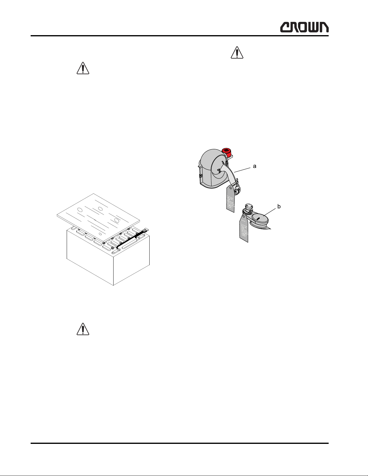
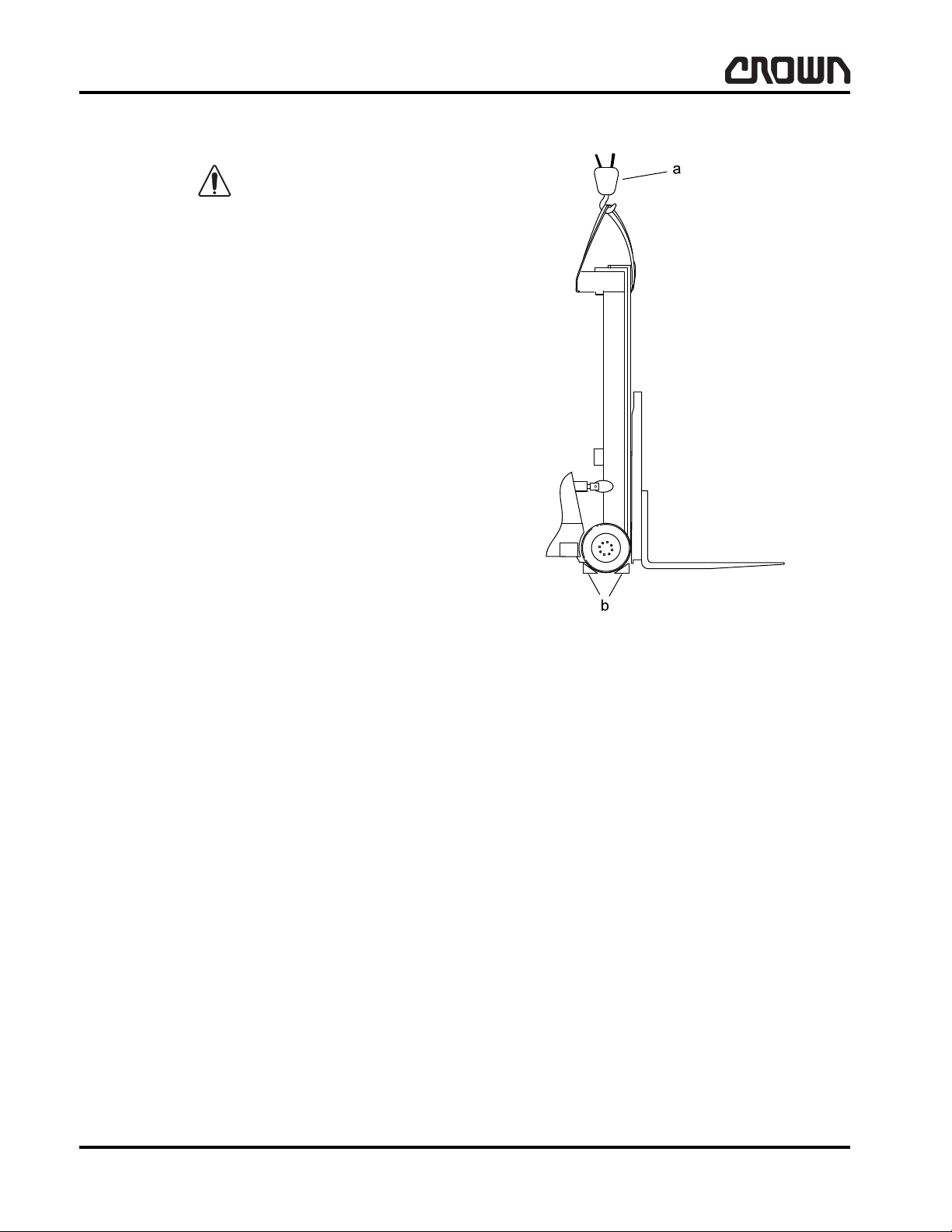
Battery Removal
When removing the battery, move truck to area intended for battery care. Floor must be level. Turn key
switch or toggle switch to "OFF" position and remove
key. Disconnect battery and lockout or tagout truck as
described in Lockout - Tagout in this section. Never
move battery partially from truck without roller stand in
place. Lower load engaging means completely. If battery is removed with load engaging means raised, use
hoist attached to mast to provide tip over protection. Do
not allow any metallic object to come in contact with the
top of the battery cells. This may cause a short circuit
when removing, transporting the battery. Use an insulator (such as plywood) to cover the top of the battery
before and during removal.
Make certain same battery or battery of equal weight is
loaded into truck for truck stability. See nameplate for
minimum battery weight.
Lockout - Tagout
Always turn key switch to "OFF", remove key and apply
tag to multi-function control handle Item 1 and/or steering tiller Item 2 with cable tie warning others truck is
being serviced.
Figure 8251
Battery Installation
When installing the battery, move truck to area intended for battery care. Floor must be level. Turn key
switch or toggle switch to "OFF" position and remove
key. Lockout or tagout truck as described in Lockout Tagout in this section. If battery was removed with load
engaging means raised, use hoist attached to mast to
provide tip over protection. Do not allow any metallic
object to come in contact with the top of the battery
cells. This may cause a short circuit when transporting
or installing the battery. Use an insulator (such as plywood) to cover the top of the battery before and during
installation.
Figure 16925-01
a
Multi-function Control Handle
b
Steering Tiller
When maintenance is to be performed and th e bat tery
will be left in the truck, remove the main power fuses
and install a commercially available lockout device on
the battery connector.
When maintenance is performed and the battery is removed from the truck, remove main power fuses, install
a lockout device on the trucks battery connector if possible, or if possible install a tag with a cable tie on the
trucks battery connector so it cannot be removed easily
warning that the truck is not available for operation.
03 Rev. 9/07
6
MA-1055-101
Crown 2006 PF15396-2 Rev. 9/07
Page 24
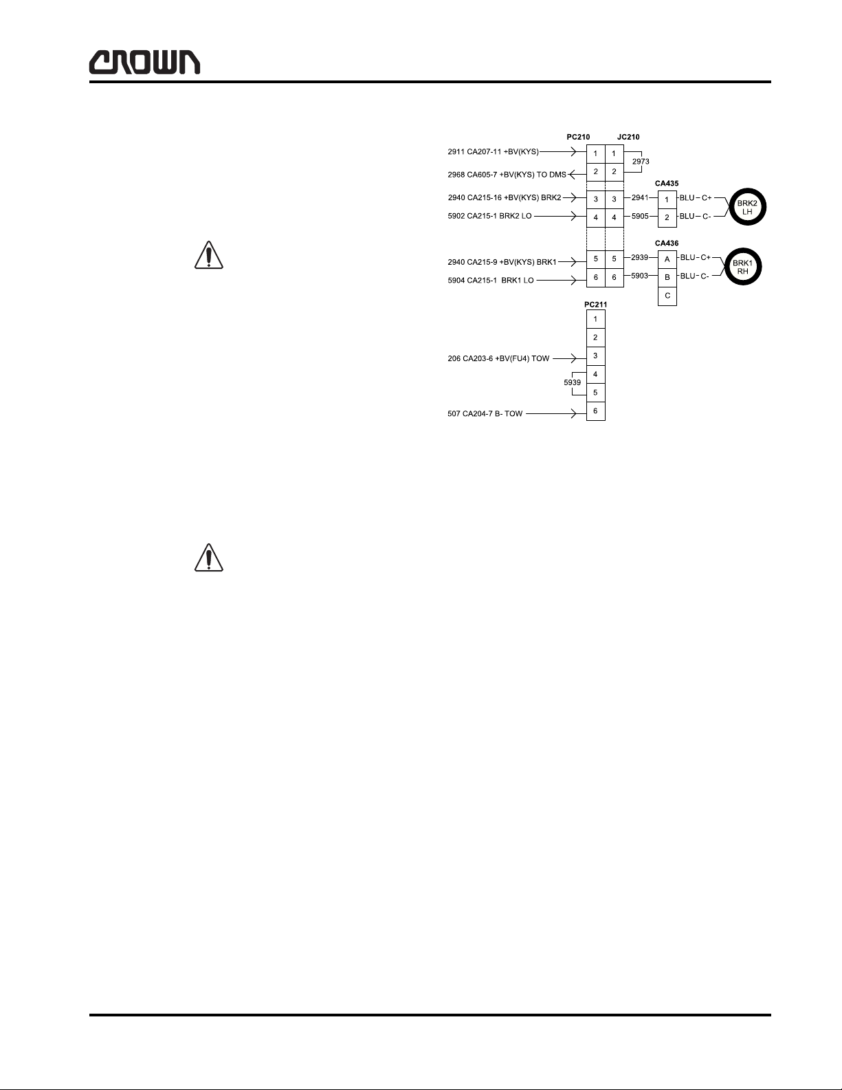
Brake Release Instructions
WARNING
CAUTION
Tow Condition Note:
- Disconnect PC210 From JC210
- Connect PC211 Into JC210
RC 5500 series trucks ship with sprin g applied/e lectrically released brakes. Power m ust be applied to the
brake circuit to release brakes for towing/unloading.
Equipment required: Crown wire harness part number
139956-001 or equivalent.
Extreme care must be taken when using this method to
release the brakes. With brakes released on uneven
surfaces, vehicle will roll.
No battery installed method
1. Open vehicle "desktop" cover and disconnect harness connector CA210 (near power fuses).
2. Plug harness (139956-001) into harness plug
JC210.
SAFETY
Control of Hazardous Energy
3. Apply 18-24 volts (DC) to harness to release
brakes.
4. Once vehicle has been moved, remove power to
harness and reconnect CA210.
Do not apply more than 28 volts (DC) to brake release
harness. Brake coil damage will occur.
Battery installed method
1. With battery unplugged from vehicle, unplug harness connector CA210 (located under desktop
cover).
2. Plug JC210 into PC211 (located in same area) on
vehicle.
3. Plug battery into vehicle battery connector to release brakes.
4. Once vehicle has been moved, disconnect battery
and reconnect CA210.
Figure 16926
Crown 2006 PF15396-3 Rev. 9/07
MA-1055-102
03 Rev. 9/07
7
Page 25
SAFETY
WARNING
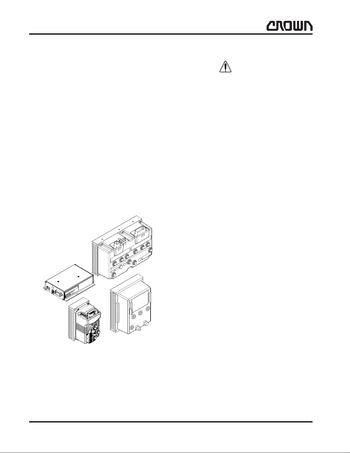
Truck Modules
Control of Hazardous Energy
Capacitance
Due to capacitance voltage present in the traction motor controller and lift motor controller, whenever performing maintenance which may permit contact with
the bus bars and associated power cables, discharge
the capacitors.
• Move truck to a secure non-traffic maintenance
area with a level floor.
• Lockout or tagout truck as described in Lockout -
Tagout in this section.
• Disconnecting the battery will discharge the capac-
itors. Once the dash display flashes, the capacitors
are discharged. T wo alternative methods of discharging these capacitors are to disconnect the
battery and hold the key switch in the "start" position for 10 seconds or disconnect the battery and
connect a 200 ohm, 2 watt resistor betw ee n th e
positive and negative terminals on the controller.
• Turn key switch to "OFF", remove key.
Hydraulic
AVOID HIGH PRESSURE FLUIDS – Escaping fluid
under pressure can penetrate the skin causing serious
injury. Relieve pressure before disconnecting hydraulic
lines. Tighten all connections before applying pressure. Keep hands and body away from pin holes which
eject fluids under high pressure. Use a piece of cardboard or paper to search for leaks. Do not use your
hand.
Any fluid injected into the skin under high pressure
should be considered as a serious medical emergency
despite an initial normal appearance of the skin. There
is a delayed onset of pain, and serious tissue d amage
may occur. Medical attention should be sought immediately by a specialist who has had experience with this
type of injury.
When maintenance is to be performed on the hydraulic
system, make certain the hydraulic system is not under
pressure by:
• Move truck to a secure non-traffic maintenance
area with a level floor.
• No load on forks.
• Completely lower load engaging means (mast) or,
if required for maintenance, block mast sections at
the appropriate height as described in Mast of this
section.
• Lockout or tagout truck as described in Lockout -
Tagout in this section.
• Depressurize hydraulic reservoir by momentarily
opening cap on reservoir before disconnecting any
hydraulic lines or components.
• Operate hydraulic levers to remove any hydraulic
pressure that may be present.
Figure 16927
03 Rev. 9/07
8
MA-1055-103
Crown 2006 PF15396-4 Rev. 9/07
Page 26
SAFETY
WARNING
WARNING
WARNING
WARNING
Control of Hazardous Energy
Towing Truck
Refer to the following guidelines when towing the truck:
Towing by Pulling in
Power Unit First Direction
• Towed truck must always maintain three contact
points with floor and/or towing device.
• Do not make sharp turns when lifting/towing truck.
• Towed vehicle forks should be empty and no more
than 305 mm (12.0 in) off floor. If possible, tilt forks
back and center sideshifter.
• Extreme care must be taken when using this
method to release the brakes. With brakes released on uneven surfaces, vehicle will roll.
• Provide a safe distance for truck to coast to stop.
• Excessive acceleration by towing vehicle, or drag
caused by towed vehicle (i.e., brake drag, drive
unit drag, wheel drag, etc.) will greatly increase requirements to pull or push a vehicle.
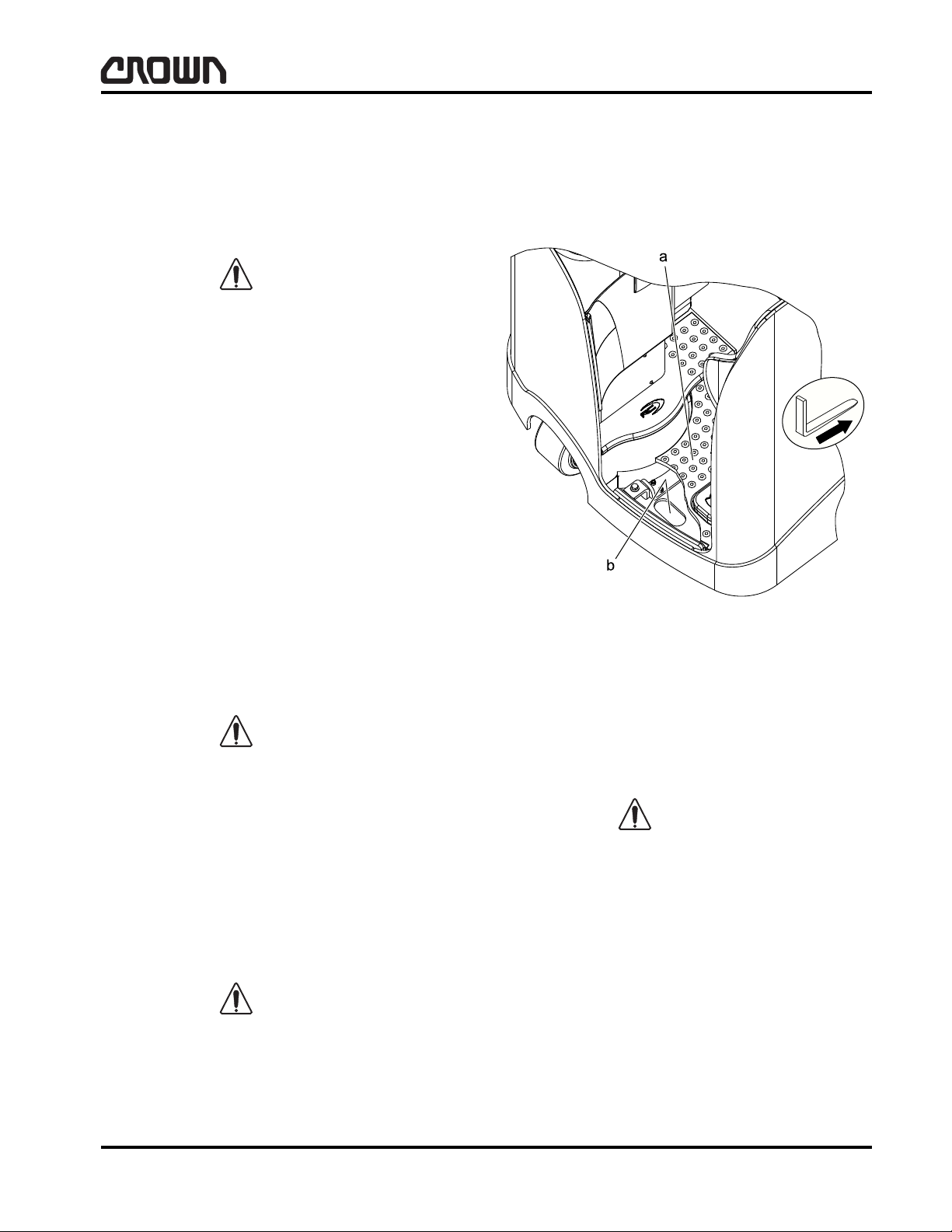
Preparing Truck For Towing:
• When attaching towing device to lift truck to be
towed, a slotted hole has been provided on rear
bottom side of power unit. Firmly attach tow device
in this area. Fasten so as not to loosen or disengage during towing.
• Power must be applied to the brake circuit to re-
lease brakes for towing. Refer to Brake Release
Instructions in this section.
• Turn power OFF.
Truck will be difficult to steer. Use extreme caution.
• Driver will be required to steer truck, as there is no
power assist from hydraulics. Truck will coast to
stop.
Towing Device Requirements:
• Towing device/vehicle must have pulling/braking
capacity greater than 3600 kg (8000 lb).
• Brakes on towed truck will not operate.
Towing mechanism attachment must not intrude more
than 40 mm (1.6 in) into floorboard cavity. Failure to
observe this WARNING could result in damage to floorboard components.
Figure 18645
a
Floorboard (cutout to show slotted hole)
b
Slotted Hole
Towing Guidelines:
• Maximum travel speed while towing truck is
3.2 kph (2 mph).
Truck will be difficult to steer. Use extreme caution.
• Driver will be required to steer truck, as there is no
power assist from hydraulics.
• Truck will coast to stop.
• Operator actions: see WARNINGS above.
Crown 2006 PF15396-5 Rev. 9/07
MA-1055-104
03 Rev. 9/07
9
Page 27

SAFETY
WARNING
WARNING
WARNING
WARNING
Control of Hazardous Energy
Towing by Pulling
in the Forks First Direction
Towing by pulling in the forks first direction is not
recommended.
Towing by Lifting Truck and
Pulling in Power Unit First Direction
• Do not lift towed truck higher than 51 mm (2.0 in)
off floor.
• Towed truck must always maintain three contact
points with floor and/or towing device.
• Do not make sharp turns when lifting/towing truck.
• Towed vehicle forks should be empty and no more
than 305 mm (12.0 in) off floor. If possible, tilt forks
back and center sideshifter.
• Extreme care must be taken when using this
method to release the brakes. With brakes released on uneven surfaces, vehicle will roll.
Towing Guidelines:
• Maximum travel speed while towing truck is
3.2 kph (2 mph).
Truck will be difficult to steer. Use extreme caution.
• No operator should be on lifted and towed truck.
• Operator actions: see WARNINGS above.
Towing by Lifting Truck and
Pulling in the Forks First Direction
Towing by lifting truck and pulling in the forks first
direction is not recommended.
Preparing Truck For Towing:
• Power must be applied to the brake circuit to re-
lease brakes for towing. Refer to Brake Release
Instructions in this section.
• Turn power OFF.
Towing Device Requirements:
• Towing device must have lifting capacity of
2268 kg (5000 lb) at load position at slot opening in
bottom of power unit.
• Towing device must have pulling/pushing/braking
capacity greater than 3600 kg (8000 lb).
• Ensure that a stem or ball capable of stated pulling/
pushing/braking capacity, and of such a design as
to prevent disengagement during towing oper ation,
is used.
• When attaching towing device to lift truck to be
towed, engage in slot located in rear , lower portion
of power unit skirt.
03 Rev. 9/07
10
MA-1055-105
Crown 2006 PF15396-6 Rev. 9/07
Page 28
SAFETY
WARNING
NOTE
Side
Steer
Wheel
Control of Hazardous Energy
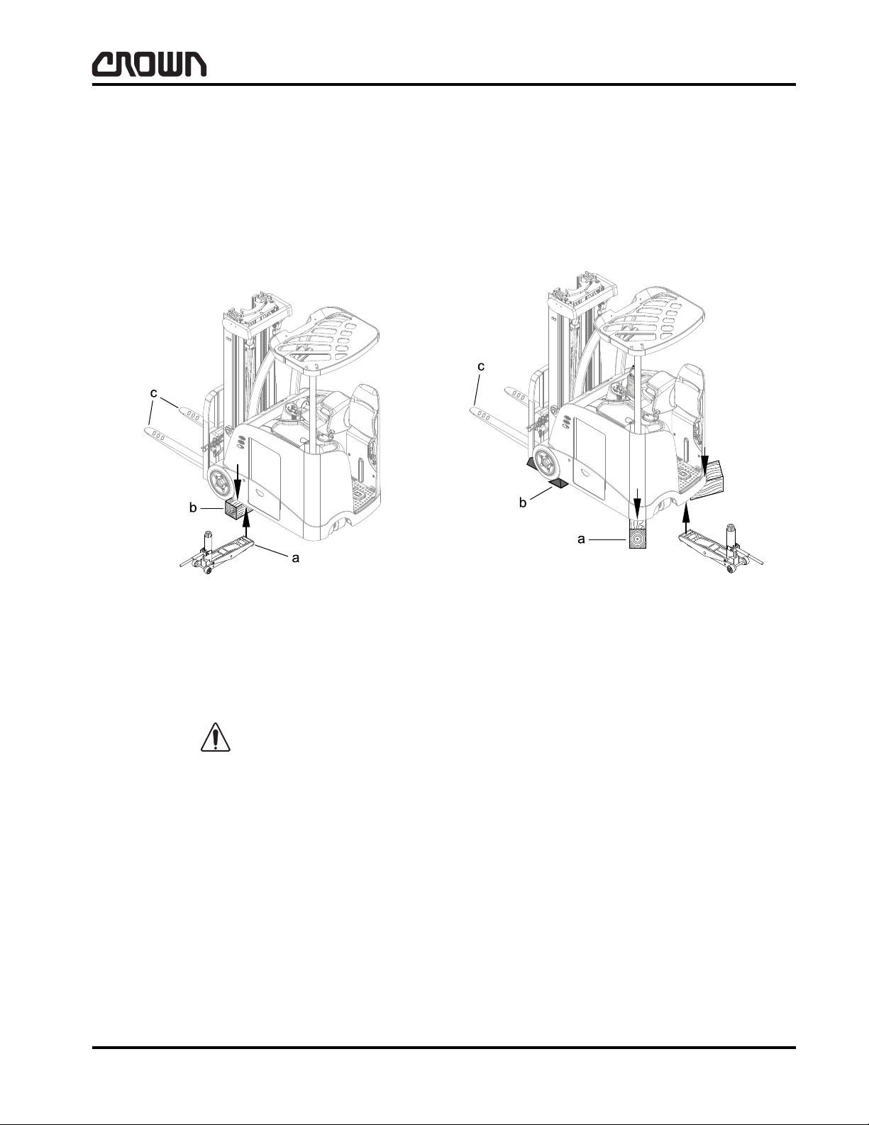
Lifting and Blocking
Move truck to a secure non-traffic maintenance
•
area with a level floor.
• No load on forks.
• Lockout or tagout truck as described in Lockout -
Tagout in this section.
NOTES:
• Hydraulic Jack Capacity: 3620 kg (8000 lb)
• Crown Part Number: 122599
• Collapsed Height Minimum: 60 mm (2.25 in)
• Raised Height Maximum: 400 mm (16 in)
Figure 16928-01
a
Use Serated Pads on Jack and Position Jack 75 mm (3.0 in)
Inward on a Flat Surface
b
Hardwood Block One Side of Truck Only to Height as
Required – Not to Exceed 162 mm (8.0 in)
c Do Not Raise Forks More than 380 mm (15 in) from Floor
Truck stability decreases dramatically if truck skirt is
raised more than 140 mm (5.5 in) or 15°. Attach sling
and overhead lifting device to all cross members of the
mast to prevent truck from tipping over when raising
one side of the truck.
Figure 16929-01
a
Use Hardwood Blocks to Set Height as Required – Not to
Exceed 162 mm (8.0 in)
b
Wheel Chock Both Drive Wheels
c Do Not Raise Forks More than 380 mm (15 in) from Floor
Position hardwood blocks as shown when lifting and
blocking the truck.
Crown 2006 PF15396-7 Rev. 9/07
MA-1055-106
03 Rev. 9/07
11
Page 29
SAFETY
Control of Hazardous Energy
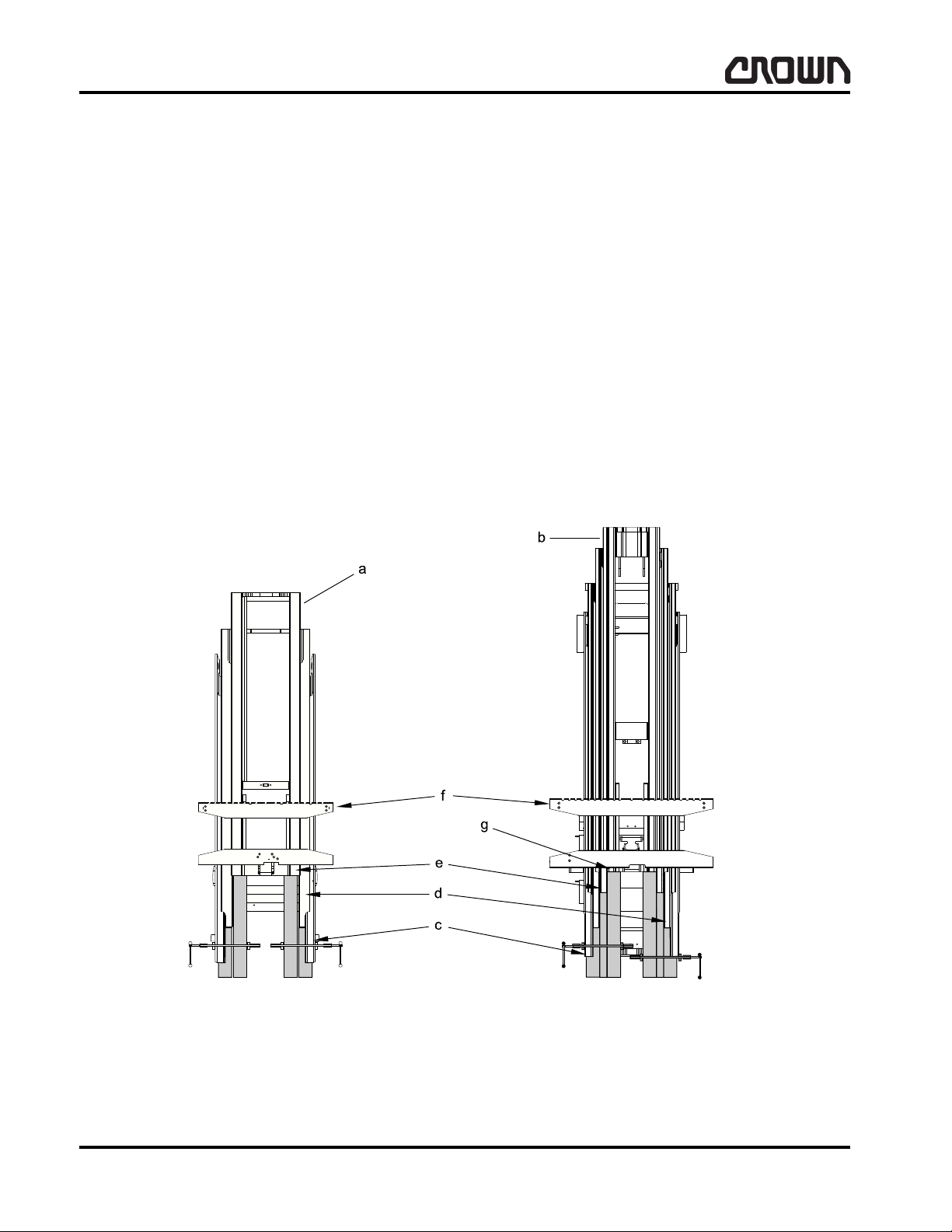
Mast
Blocking Masts
Use 100 x 100 mm (4 x 4 in) or bigger hardwood blocks
of appropriate length for supporting mast channels.
Block both mast rails of each stage to maintain stability .
Remove any carriage mounted accessory (i.e., carton
clamp, etc.) except sideshifters before blocking masts.
These accessories add significant weight to the mast.
• Move truck to a secure non-traffic maintenance
area with a level floor.
• Chock wheels (refer to Lifting and Blocking in this
section).
• Connect battery.
• Raise forks and position blocks under second
stage mast as shown.
• Using a clamp or ratchet tie down, secure blocks to
mast channel as shown.
• Lower mast and position appropriate length blocks
under third stage mast as shown.
• Lower mast and position appropriate length block
under fourth stage mast (or inner) on quad ma st as
shown.
• Using a clamp or ratchet tie down, secure blocks to
mast channel or second stage block as shown.
• Lower fork carriage until carriage rests on stops or
place blocks under carriage and lower until weight
rests on blocks.
• Lockout or tagout truck as described in Lockout -
Tagout in this section.
a
TT Mast e Third Stage Mast
b
Quad Mast f Fork Carriage (Shown Raised Slightly for Clarity)
c Second Stage Mast g Fourth Stage Mast (or Inner)
d First Stage Mast (Mainframe or Outer Mast)
MA-1055-107
03 Rev. 9/07
12
Figure 16930-01
Crown 2006 PF15396-8 Rev. 9/07
Page 30
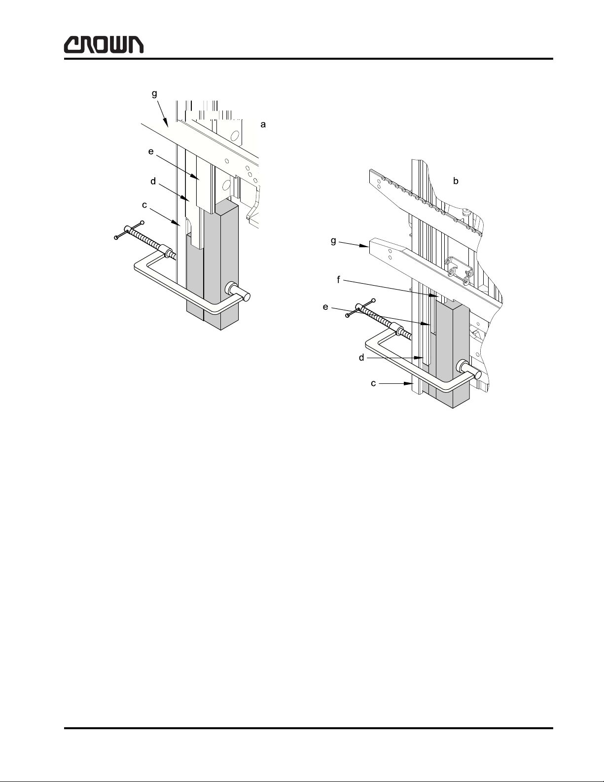
SAFETY
Control of Hazardous Energy
a
TT Mast e Third Stage
b
Quad Mast f Fourth Stage (or Inner Mast)
c First Stage (Mainframe or Outer Mast) g Fork Carriage
d Second Stage
Figure 16931-01
Crown 2006 PF15396-9 Rev. 9/07
MA-1055-108
03 Rev. 9/07
13
Page 31
SAFETY
WARNING
Control of Hazardous Energy
Disconnecting Tilt Cylinder
Wear appropriate items, such as safety glasses and
steel-toed shoes whenever performing maintenance
work. Do not place fingers, hands or arms through
mast or position them at pinch points.
In this section you may be required to lift and block the
truck and mast or raise and lower different components
for removal and installation. Make sure lifting device
and sling are sufficiently rated to withstand the weight
being lifted. Never work under or around a truck that is
not properly secured. Refer to truck Data Plate for truck
weight information.
It will be necessary to disconnect and remove the battery from the truck, disconnect tilt cylinders from the
mast, disconnect electrical connections and hydraulic
lines. "Control of Hazardous Energy" section provides
information for performing the above procedures along
with some additional information on other procedures
dealing with truck maintenance. This section should be
read and reviewed prior to mast removal, installation
and maintenance as outlined in this section.
When the tilt cylinders are disconnected from the hydraulic system or from the mounting brackets, the mast
must be secured to keep the mast from pivoting toward, or away from the truck.
• Move truck to a secure non-traffic maintenance
area with a level floor.
• Lower load engaging means (mast) completely . No
load on forks.
• Lockout or tagout truck as described in Lockout -
Tagout in this section.
• Chock wheels (refer to Lifting and Blocking in this
section).
• Attach a sling and lifting device to all mast top
cross braces so movement will be minimal when tilt
cylinders are disconnected.
Figure 16932-01
a
Attach Lifting Device to All Top Cross Braces and Center to
Maintain Balance
b
Wheel Chocks
03 Rev. 9/07
14
MA-1055-109
Crown 2006 PF15396-10 Rev. 9/07
Page 32

SAFETY
Control of Hazardous Energy
Removing Mast
1. Move truck to a secure non-traffic maintenance
area with a level floor.
2. Lockout or tagout truck as described in Lockout Tagout in this section.
3. Remove battery.
4. Remove forks.
5. Operate all hydraulic levers to remove any hydraulic pressure in the system.
6. Disconnect lift cylinder hydraulic lines, accessory
cables and accessory hydraulic lines between
power unit and mast if present. Use container to
catch hydraulic oil.
7. Disconnect wiring between mast and power unit.
8. Support mast as described in Disconnecting Tilt
Cylinders in this section.
9. Chain mast sections together at the upper crossbraces. Chain fork carriage to lower mast crossbrace. This will keep carriage and mast sections
from moving when the mast is laid down.
11. Remove pivot block mounting bolts. If pivot blocks
are to be removed, note number and location of
shims between pivot blocks and mast.
12. Move mast away from truck and lay mast on level
floor with the truck side of the mast on the floor.
Figure 16934-01
a
Power Unit
b
Mast
cShim
10. Remove retaining rings connecting tilt cylinders to
the mast.
Figure 16933-01
a
Mounts to Truck Frame
b
Remove Retaining Ring
c Part of Mainframe
Crown 2006 PF15396-11 Rev. 9/07
MA-1055-110
03 Rev. 9/07
15
Page 33

Notes:
C
16
Page 34

SAFETY
Cleaning of Material Handling Equipment
Cleaning of Material Handling
Equipment
Cleaning Methods
The preferred method of cleaning built up dirt and dust
from electric material handling equipment is dry pressured air . For localized deg reasing, use of an appropriate solvent is recommended.
If these methods are not effective and power washing
is the only alternative, extreme care must be exercised.
Electrical components including connectors, terminal
boards and wiring can be permanently damaged from
water and/or cleaning solvents. Mineral and chemical
residue left on or in components (i.e., circuit boards,
contactors, encoders, switches, potentiometers, etc.)
after washing is a proponent of oxidation and corrosion.
Functional integrity of contaminated components may
be questionable. Nuisance fault logging, intermittent
Crown Cleaning Products Chart
operation or immediate failure could be the result ant of
power washing. For these reasons all electronic components including motors must be protected. Component removal is the best method to eliminate the risk of
damage.
Power washing will also remove and/or destroy lubricants in or on the surface of shaf ts, unsealed bea rings,
hinges, exposed gears, bushings, chains, linkages,
etc. These Items must also be protected or properly lubricated after cleaning.
Consideration must also be given to metal surfaces.
The cleaning process can strip away paint and protective coatings applied to components (i.e., hydraulic
lines, terminal strips, linkages) for freezer/corrosion environment. Paint and/or protective coating must be reapplied to these areas to reduce the ch ance of oxidation and corrosion.
Before installing removed components, lubricating or
returning the equipment to service it must be free of
solvent residue and thoroughly dry.
Cleaner Type Part Number Package Quanity
Degreaser & Cleaner 363105-001
363105-012
All Purpose Cleaner 363114-001
363114-012
Glass Cleaner 363101-001
363101-012
Waterless Hand Cleaner 363111-001
363111-012
Pumiced & Smooth Hand Cleaner 363112-001
363112-004
Wall Mounted Deluxe Soap Dispenser 363122 Used with 363112-001
Tough On Grease 063009-005 1 Gallon Jug
20 oz. Can
(12) 20 oz. Cans
20 oz. Can
(12) 20 oz. Cans
20 oz. Can
(12) 20 oz. Cans
15 oz. Tube
(12) 15 oz. Tubes
1 Gallon Jug
(4) 1 Gallon Jugs
Crown 2000 PF11969-1 Rev. 10/06
MA-1140-050
02 Rev. 10/06
17
Page 35

Notes:
18
Page 36

INTRODUCTION
19
Page 37

Notes:
20
Page 38

INTRODUCTION
Introduction
Introduction
This manual is intended for the service technician who
is seeking information about maintenance and service
replacement parts. It contains a section on troubleshooting which will enable a qualified technician to locate and solve problems which may occur.
Operation Instructions
This manual does not contain operator instructions.
Operator Instructions in tag or booklet form are sent
with each truck. Additional copies can be ordered if required. These booklets are for you and your personnel
to insure years of safe, trouble-free operation of your
Crown Lift Truck. Fo r standup ride r counterbalance operator instructions, refer to Crown publication, "Operator Manual RC 5500 Series".
Operater Training
Crown produces a complete series of operator tra ining
programs available through your local Crown dealer. A
complete listing of these and other available programs
can also be found under "Training" on
www.crown.com.
Service Training
Complete Service Training is available for the lift truck
technician covering all Crown Lift Trucks, module systems, wire guidance, hydraulic and electrical systems.
To obtain more information concerning service training, contact your Crown Dealer or under "Training" on
www.crown.com.
Replacement Parts
When ordering replacement parts from this manual, always specify, along with part number, model and serial
number of the truck. This information will further enable
us to give correct, fast and efficient service.
For current part number of service manuals, operator
manuals, operator training programs, truck capacities
and technical specifications, contact your local dealer
or at www.crown.com.
This manual is arranged according to major sections
which covers maintenance and replacement p arts. The
sectional descriptions are as follows:
Maintenance Replacement Parts
Section Description Section Description
M1 Lubrication and Adjustment 1 Po we r Unit Parts
M2 Hydraulic 2 Hydraulic Parts
M3 Drive Unit 3 Drive Unit Parts
M4 Electrical 4 Electrical Parts
M5 Brake 5 Brake Parts
M6 Steering 6 Steering Parts
M7 Lifting Mechanism 7 Lifting Mechanism Parts
M8 Cylinders 8 Cylinder Parts
M9 Platform 9 Platform Parts
M10 Glossary 10 Labels and Decals
Crown 2007 PF15672-1
ITD-1055-001
21
Page 39

INTRODUCTION
RC5530 -30
Series Update
Significant change(s) to the produ ct
that would not merit a new series
number (generation).
5 = AC traction as standard (only) offering.
*Capacity
30 = 1360 kg (3000 lbs)
35 = 1590 kg (3500 lbs)
40 = 1815 kg (4000 lbs)
1.5 = 1500 kg (3307 lbs)
1.6 = 1600 kg (3527 lbs)
1.8 = 1800 kg (3968 lbs)
Image Generator
RC - Rider Counterbalance
Relative Size or Performance
1 = 347 mm (13.66 in) battery compartment
2 = 405 mm (15.94 in) battery compartment
3 = 462 mm (18.19 in) battery compartment
4 = 522 mm (20.55 in) battery compartment
Series
Major technical and design changes
making the product a new and
improved generation.
Hydraulics System
0 = DC Hydraulics
5 = AC Hydraulics
Base or Custom
C = Custom (fleet) truck
No letter = Base truck
MODEL NUMBER EXAMPLE
Introduction
The data plate for the RC 5500 series truck is located
on the battery compartment wall and includes a model
number and truck data number. From these two numbers, you can identify the truc k model, series, series
updates, determine relative size and performance, capacity and specific truck data. The following pages e xplain the model & truck data numbering system.
The example of the model number shown
(RC 5530 -30) is a RC 5500 series. It has an AC traction motor with a 462 mm (18.19 in) battery compartment. It also has DC hydraulics and has a capacity of
1360 kg (3000 lbs).
*Actual rated capacity may vary, depending on special
equipment or modifications. Consult capacity plate located on the overhead guard.
22
ITD-1055-002
Figure 14936
Crown 2007 PF15672-2
Page 40

INTRODUCTION
- TT 190 D - RA C R 3 C H A
Drive Tire
PA = Standard Siped Poly
PB = Non-Marking Siped Poly
PC = Standard Smooth Poly
PD = Non-Marking Smooth Poly
RA = Standard Smooth Rubber
RB = High Density Non-Marking Rubber
RC = High Density Smooth Rubber
RD = Non-Marking Smooth Rubber
RE = Standard Lug Rubber
RF = High Density Non-Marking Lug Rubber
RG = High Desnity Lug Rubber
RH = Non-Marking Lug Rubber
Steering
F = Forward
R = Reverse
Standard/Custom/Special
- = Standard
C = Custom
S = Special
Hydraulic Accessories
- = No Hydraulic Accessory
A = 2 High
C = 1 Low
D = 1 High/1 Low
Cold Conditioning
- = No Cold Conditioning
F = Freezer Conditioning
C = Corrosion Conditioning
Mast Type
TT = Telescopic Triple Stage
QD = Telescopic Four Stage
-- = Power Unit Only
Travel Alarm & Light Package
Option
- = No Travel Alarm & Lights
1 = Strobe Light
2 = Travel Alarm
3 = Worklights
4 = Travel Alarm & Strobe Light
5 = Worklights & Strobe Light
6 = Travel Alarm, Worklights, &
Strobe Light
7 = Travel Alarm & Worklights
Lift Height
Displays Lift Height
Dimension i.e.
190 = 4825 mm (190 in)
208 = 5283 mm (208 in)
Sideshifter Type
C = Cascade
- = No Sideshifter
Battery Compartment Size
B = 347 mm (13.66 in)
C = 405 mm (15.94 in)
D = 462 mm (18.19 in)
E = 522 mm (20.55 in)
Lift System
A = AC
D = DC
Floor Board
H = Hinged
E = Flex Ride
Introduction
Truck data numbers provides you and your Crown
dealer with a wealth of information to insure the selection of proper parts for your Crown tr uck. You may sim-
ply provide this number to your Crown dealer, or use
the following breakdown if selecting your own part
numbers or service information from this manual.
Crown 2007 PF15672-3
ITD-1055-003
23
Page 41

Notes:
24
Page 42

LUBRICATION & ADJUSTMENT
25
Page 43

Notes:
26
Page 44

LUBRICATION & ADJUSTMENT
Lubrication and Adjustment
Lubrication and Adjustment
To obtain maximum life of any industrial equipment, a
well planned maintenance program (PM), performed
by qualified technical personnel should be followed. In
conjunction with, and an integral part of, any planned
maintenance program should be daily operator input.
Operator involvement can greatly reduce truck down
time, assist in determining planned maintenance (PM)
schedules and ultimately save money. For these reasons, Crown recommends a checklist similar to the Operators Daily Checklist shown below.
Before performing maintenance to any unit, it should
be taken to an area set aside for maintenance o r a section where there is adequate space to perform required
work. This is a must to insure the safety of others and
to insure that proper maintenance is performed to the
unit.
If desired, padded packs of this checklist (OF-3772)
are available through your Crown dealer.
Crown 2007 PF15686-1 Rev. 6/08
Figure 14990
M1.0-1960-500
01 Rev. 6/08
27
Page 45

LUBRICATION & ADJUSTMENT
Lubrication and Adjustment
The following is a list of lubricants and maintenance
products recommended when doing Planne d Maintenance on Crown Lift Trucks.
Lubrication Identification Chart
Type of Lubricant Part Number Package Quantity
363514-001
A Gear Lube 75W-90 (Synthetic)
B Grease (Multi-Purpose)
(1)
BB
BBB Food Grade Grease (Multi-Purpose)
DD
DDD Hydraulic Oil - DTE24 063001-021 1 Gallon
Grease (Low Temperature)
C Oil (SAE 40)
D Hydraulic Oil
(1)
Hydraulic Oil (Low Temp)
E Channel Grease
F Gear Grease
Chain & Cable Lube
G
Premium Chain & Cable Lube
363514-002
063002-044
063002-034
063002-045
063002-017
063002-046
363002-001
363002-030
363504-101
363504-106
363505-101
363505-106
063002-024
063002-022
063002-024
063002-022
363107-001
363107-012
363115-001
363115-012
1 Quart
12 Quart/Case
5 Gallon
14 oz Cartridge
(40) 14 oz Cartridges
14 oz Cartridge
(40) 14 oz Cartridges
14 oz Cartridge
(30) 14 oz Cartridges
1 Gallon
(6) 1 Gallon
1 Gallon
(6) 1 Gallon
14.5 oz Cartridge
35 lb Pail
14.5 oz Cartridge
35 lb Pail
15 o z Can
(12) 15 oz Cans
12 o z Can
(12) 12 oz Cans
H Final Finish - Rubber & Vinyl Dressing
I Grease (Lift Pump Coupling)
J Brake Fluid - Dot 5
K Grease (Wheel Bearing)
L Metal Assembly Spray 063002-021 16 oz Spray
M Silicon Grease (Clear) 063002-020 5.3 oz Tube
(1)
Trucks operated in below freezing temperatures must use Low Temp Hydraulic Oil & Grease.
M1.0-1960-501
01 Rev. 6/08
363129-001
363129-012
063002-039
127801S
063004-002
063004-003
063002-034
063002-045
11 oz Can
(12) 11 oz Cans
1 lb Jar
1 oz Jar
12 oz
1 Gallon
14 oz Cartridge
(40) 14 oz Cartridges
28
Crown 2007 PF15686-2 Rev. 6/08
Page 46

LUBRICATION & ADJUSTMENT
Lubrication and Adjustment
Lubrication Identification Chart
Type of Lubricant Part Number Package Quantity
Brake & Parts Cleaner
Low VOC Brake & Parts Cleaner
N
Non-Flammable Brake & Parts Cleaner
O Penetrating Lubricant
P Premium Formula Multi-Purpose Grease
Q White Lithium Grease
R Choke & Carburetor Cleaner
Contact Cleaner - Non-Flammable
S
Contact Cleaner
T Electrical Connector Oxidation & Corrosion Inhibitor 127189-001 30 cc
U Battery Cleaner
363102-001
363102-012
363103-001
363103-012
363116-001
363116-012
363104-001
363104-012
363108-001
363108-012
363110-001
363110-012
363109-001
363109-012
363106-001
363106-012
363128-001
363128-012
363124-001
363124-012
14 oz Can
(12) 14 oz Cans
14 oz Can
(12) 14 oz Cans
19 oz Can
(12) 19 oz Cans
20 oz Can
(12) 20 oz Cans
11 oz Can
(12) 11 oz Cans
11 oz Can
(12) 11 oz Cans
15 oz Can
(12) 16 oz Cans
10 oz Can
(12) 10 oz Cans
11 oz Can
(12) 11 oz Cans
18 oz Can
(12) 18 oz Cans
V Battery Protector
W Food Grade Machine Lubricant
X Food Grade Silicone Spray
363125-001
363125-012
363127-001
363127-012
363126-001
363126-012
15 oz Can
(12) 15 oz Cans
12 oz Can
(12) 12 oz Cans
11 oz Can
(12) 11 oz Cans
Crown 2007 PF15686-3 Rev. 6/08
M1.0-1960-502
01 Rev. 6/08
29
Page 47

LUBRICATION & ADJUSTMENT
Lubrication and Adjustment
Alternate Lubricants & Fluids Chart
Type of Lubricant Product Name
A Gear Lube 75W-90 (Typical)
B Grease (Multi-Purpose)
BB
Grease (Low Temp)
(2)
Mobilube1 SHC 75W-90* API GL-4
Dubois EG 0-75 & 90*
Mobilgrease XHP 222 Special
Union Unoba EP No 2
Retinax A
(1)
LM Grease
Unirex EP-2
Lubriplate
Alvania RA
Helveum O
(1)
(1)
Manufacturer
/ Distributor
Mobil
Dubois Chemical
Mobil
Union 76 Co.
Shell
Burmah Castrol
Exxon
Fiske Bros Refining Co.
Shell
Burmah Castrol
BBB Food Grade Grease (Multi-Purpose) Petro Canada Purity FG Petro Canada
C Oil (SAE 40)
D Hydraulic Oil Crown Crown
DD
DDD
Hydraulic Oil (Low Temp)
Hydraulic Oil - DTE24
(3)
(2)
Crown
Mobil DTE 24
Crown
Mobil
E Channel Grease Factran #2 Standard Oil Co.
F Gear, Channel & Shaft Grease Molykote BR-2 Plus Dow Corning
Chain & Cable Lube Crown Crown
G
Premium Chain & Cable Lube Crown Crown
H Final Finish - Rubber & Vinyl Dressing Crown Crown
I Grease (Lift Pump Coupling) Nyogel 774F-MS NYE Lubricants
J Brake Fluid - Dot 5 Q2-1141 Silicon Brake Fluid Dow Corning
K Grease (Wheel Bearing)
Mobilgrease XHP 222 Special
Unirex EP-2
Lubriplate No. 1242
(1)
Mobil
Exxon
Fiske Bros. Refining Co.
L Metal Assembly Spray Dow Corning Dow Corning
M Silicon Grease (Clear) Dow Corning 1 11 Compound Dow Corning
Brake & Parts Cleaner Crown Crown
N
Low VOC Brake & Parts Cleaner Crown Crown
Non-Flammable Brake & Parts Cleaner Crown Crown
(1)
Denotes allowable substitutes, contact factory if unavailable.
(2)
Trucks operated in below free zing temperatures must use Low Temp Hydraulic Oil & Grease.
(3)
Premium antiwear hydraulic oil used in blending with low temp oil.
01 Rev. 6/08
30
M1.0-1960-503
Crown 2007 PF15686-4 Rev. 6/08
Page 48

LUBRICATION & ADJUSTMENT
Lubrication and Adjustment
Alternate Lubricants & Fluids Chart
Type of Lubricant Product Name
O Penetrating Lubricant Crown Crown
P Premium Formula Multi-Purpose Grease Crown Crown
Q White Lithium Grease Crown Crown
R Choke & Carburetor Cleaner Crown Crown
S Contact Cleaner Crown Crown
Electrical Connector Oxidation &
T
Corrosion Inhibitor
U Battery Cleaner Crown Crown
V Battery Protector Crown Crown
W Food Grade Machinery Lubricant Crown Crown
X Food Grade Silicone Spray Crown Crown
Nye Grease NYE Lubricants
Manufacturer
/ Distributor
Crown 2007 PF15686-5 Rev. 6/08
M1.0-1960-504
01 Rev. 6/08
31
Page 49

Notes:
32
Page 50

LUBRICATION & ADJUSTMENT
CAUTION
Lubrication and Adjustment
Component Accessibility
For regular maintenance, access to various truck components is accomplished by removing various covers/
doors. The following is a general explanation of which
cover, door, etc. that must be removed to allow for the
most efficient access when performing service and/or
maintenance to components. Refer to the figures in this
section as an aid in locating parts that require attention.
Disconnect the battery and chock all wheels before
proceeding.
Lubrication and Adjustment
Crown 2007 PF15681-1 Rev. 4/07
M1.0-1055-001
01 Rev. 4/07
33
Page 51
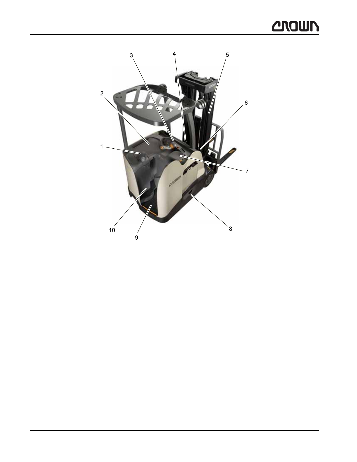
LUBRICATION & ADJUSTMENT
1 Tiller Support
2 Desktop
3 Display Panel Cover
4Front Cover
5Mast
6 Manifold Cover
7 Armrest
8 Battery Retainer
9 Floorboard
10 Steer Axle Cover
Lubrication and Adjustment
Remove tiller support to access:
• Steering control unit
Remove one screw then lift up desktop to access:
• Contactor panel (distribution panel, fuses, cont ac-
tors)
• Steering control unit
34
Figure 16020
When removing display panel cover, first remove key
from switch then remove cover to access:
• Access 1
• Multi-task handle assembly
• Key switch
• Indicator panel lights and switches
• Access 7
M1.0-1055-002
Crown 2007 PF15681-2
Page 52

LUBRICATION & ADJUSTMENT
NOTE
Lubrication and Adjustment
Remove front cover to access:
• Access 2
• Hydraulic components (lift motor, lift pump filter)
• Access 3
• Tilt cylinders
• Horn
• Battery retainer switches
• TPA (tilt position assist)
• Hydraulic reservoir
Remove manifold cover to access:
• Manifold block and solenoid valves
The mast also has several components to access:
• Chains
• Column rollers
• Chain adjust
• Accessory guide
• Pulleys
Loosen each battery retainer screw then lift and remove battery retainers to access:
• Battery rollers (battery removed)
• Battery retainer switches (left and right)
• Battery and connectors
Remove armrest cover to access:
• Armrest assembly
Remove floorboard to access:
• Brake switch (BRKS)
• Entry bar assembly and switches
• Switches (DMS1, DMS2 and DMS3)
• Brake pedal hall sensor (RPS1)
Remove steer axle cover plate to access:
• Axle assembly
• Steer motor
Remove floor suspension cover to access
• Suspension springs, linkage and damper
Lubrication
The following information provides guidelines for
proper lubrication intervals called out in the lubrication
chart. However, some operating conditions will require
more frequent checks and lubrication than listed. For
example, truck applications which operate in extreme
moisture or dust environments will require schedule
modification in each particular application.
Use high grade lubricants and fluids. Sources of these
lubricants may originate from almost any oil company;
those listed on page MA-1960-500 are typical and any
lubricant with equal specifications may be used.
On trucks equipped to operate in below freezing temperatures, low temperature hydraulic oil must be used.
All screws, washers, nuts, roll pins, retaining rings,
brake linkage, etc. need to be coated with a rust preventive (078882) to protect against corrosion. Lubrication intervals must be changed to a frequency that will
minimize corrosion and wear on moving shafts and
parts.
The truck has seven zerk fittings for lubrication purposes (nine zerks with sideshifter). Refer to the following information for specifications, locations, etc.
Crown 2007 PF15681-3
Use Planned Maintenance Inspection Report
(PF15345) for RC 5500 trucks as required to record
and assure maintenance checks.
M1.0-1055-003
35
Page 53

LUBRICATION & ADJUSTMENT
Lubrication and Adjustment
36
Figure 15977
M1.0-1055-004
Crown 2007 PF15681-4
Page 54

LUBRICATION & ADJUSTMENT
Lubrication and Adjustment
Inspection Chart 1
Index Component
I-1 Power Unit Wall Around Tilt Mounting Hardware (crack-free) Check
I-2 Tilt Cylinders, Pivot Points and Mounting Hardware Check
I-3 Pump Motor Brushes and Armature Condition Check
I-4 Battery Retainer Switches Operation N/A
I-5 Horn Operation N/A
I-6 Power Cable and Connections Check
I-7 Traction Motors Check
I-8 Parking Brake Operation N/A
I-9 Mast Mounting Hardware and Pivot Points Check
Refer to appropriate section of Service and Parts Manual for additional information concerning inspection
and/or adjustment.
Lubrication Chart 1
Index Component
Lube
Type
Quantity
60 Days
250 Hours
60 Days
250 Hours
12 Months
2000 Hours
12 Months
2000 Hours
Hydraulic Reservoir
Oil
L-1
L-2 Tilt Cylinder Zerks B As Req. Check
L-3 Drive Unit A 1 Litre (1 Qt) Check Change
L-4 Mast Pivot Zerks B As Req. Check
See Chart 1 and 2 for Lube Type designation explanation (MA-1960-500).
Lubrication intervals must be changed to a frequency
that will minimize corrosion and wear on moving parts
for trucks operated in environments with excessive
dust and moisture, freezer/corrosion applications, etc.
10 Micron
Suction Strainer
Cap Ventilating Element
D 16.6 Litre (4.4 Gal)
1
1
1
Check
1st Change
1st Change
Change
Change
Clean
Change
Crown 2007 PF15681-5 Rev. 4/07
M1.0-1055-005
01 Rev. 4/07
37
Page 55

LUBRICATION & ADJUSTMENT
Lubrication and Adjustment
38
Figure 15978
M1.0-1055-006
Crown 2007 PF15681-6
Page 56

LUBRICATION & ADJUSTMENT
Lubrication and Adjustment
Inspection Chart 2
Index Component
I-10 Forks, Carriage, Load Backrest and Attachments Check
I-11 Sideshifter (Slides, Cylinders, Mounting, etc.) Check
I-12 Load Sense Switch Check
I-13 Hydraulic Line, Hose Fittings and Connections Check
I-14 Solenoid Valves Check
I-15 Column Rollers/Channels Check
I-16 Hose Take Up Cables Check
I-17 Lift Chain Check
I-18 Cylinder Guides, Slides and Stops Check
I-19 Carriage Cylinder and Mounting Hardware Check
I-20 Mast Cylinder(s) Check
I-21 Battery Retainers Check
Refer to appropriate section of Service and Parts Manual for additional information concerning inspection
and/or adjustment.
60 Days
250 Hours
12 Months
2000 Hours
Lubrication Chart 2
Index Component
L-5 Sideshifter Zerks B As Req. Check
L-6 Mast Channels and Rollers E As Req. Check
L-7 Hoses, Cables and Pulleys H As Req. Check
L-8 Lift Chain G As Req. Check
See Chart 1 and 2 for Lube Type designation explanation (MA-1960-500).
Lubrication intervals must be changed to a frequency
that will minimize corrosion and wear on moving parts
for trucks operated in environments with excessive
dust and moisture, freezer/corrosion applications, etc.
Lube
Type
Quantity
60 Days
250 Hours
12 Months
2000 Hours
Crown 2007 PF15681-7
M1.0-1055-007
39
Page 57
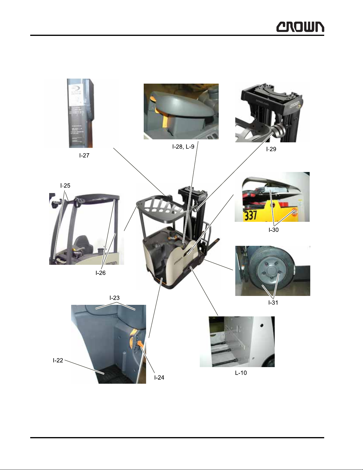
LUBRICATION & ADJUSTMENT
Lubrication and Adjustment
40
Figure 15979
M1.0-1055-008
Crown 2007 PF15681-8
Page 58

LUBRICATION & ADJUSTMENT
Lubrication and Adjustment
Inspection Chart 3
Index Component
I-22 Presence Pedal N/A
I-23 Pads Check
I-24 Suspension Lever Check
I-25 Overhead Guard and Mounting Hardware Check
I-26 3rd Post Assembly and Mounting Hardware Check
I-27 Labels/Decals Check
I-28 Armrest Check
I-29 Worklights Check
I-30 Battery and Connectors Check
I-31 Drive Tires and Lug Nuts Check
Refer to appropriate section of Service and Parts Manual for additional information concerning inspection
and/or adjustment.
Lubrication Chart 3
60 Days
250 Hours
12 Months
2000 Hours
Index Component
L-9 Armrest Sliding Surfaces M As Req. Check
L-10 Battery Rollers B As Req. Check
See Chart 1 and 2 for Lube Type designation explanation (MA-1960-500).
Lubrication intervals must be changed to a frequency
that will minimize corrosion and wear on moving parts
for trucks operated in environments with excessive
dust and moisture, freezer/corrosion applications, etc.
Lube
Type
Quantity
60 Days
250 Hours
12 Months
2000 Hours
Crown 2007 PF15681-9 Rev. 4/07
M1.0-1055-009
01 Rev. 4/07
41
Page 59

LUBRICATION & ADJUSTMENT
Lubrication and Adjustment
42
Figure 15980
M1.0-1055-010
Crown 2007 PF15681-10
Page 60

LUBRICATION & ADJUSTMENT
Lubrication and Adjustment
Inspection Chart 4
Index Component
I-32 Steering Tiller Operation N/A
I-33 Steering Control Unit Check
I-34 Contactor Panel and Tips Check
I-35 Access 1 Check
I-36
I-37 Emergency Disconnect (EDS) Check
I-38 Multi-Task Handle Switches and Linkage Check
I-39 Electrical Connections Check
I-40 Floorboard Switches and Springs Check
I-41 Brake Pedal and Switch Check
I-42 Entry Bar and Switches Check
(1)
Optional componentry.
Switch Panel (Override, Fan, Light, Dome Light)
Refer to appropriate section of Service and Parts Manual for additional information concerning inspection
and/or adjustment.
(1)
60 Days
250 Hours
Check
12 Months
2000 Hours
Lubrication Chart 4
Index Component
L-11 Multi-Task Handle Ramp and Plunger M As Req. Check
L-12 Brake Linkage and Pins B As Req. Check
L-13 Brake Pedal Zerk B As Req. Check
See Chart 1 and 2 for Lube Type designation explanation (MA-1960-500).
Lubrication intervals must be changed to a frequency
that will minimize corrosion and wear on moving parts
for trucks operated in environments with excessive
dust and moisture, freezer/corrosion applications, etc.
Lube
Type
Quantity
60 Days
250 Hours
12 Months
2000 Hours
Crown 2007 PF15681-11 Rev. 4/07
M1.0-1055-011
01 Rev. 4/07
43
Page 61

Notes:
44
Page 62
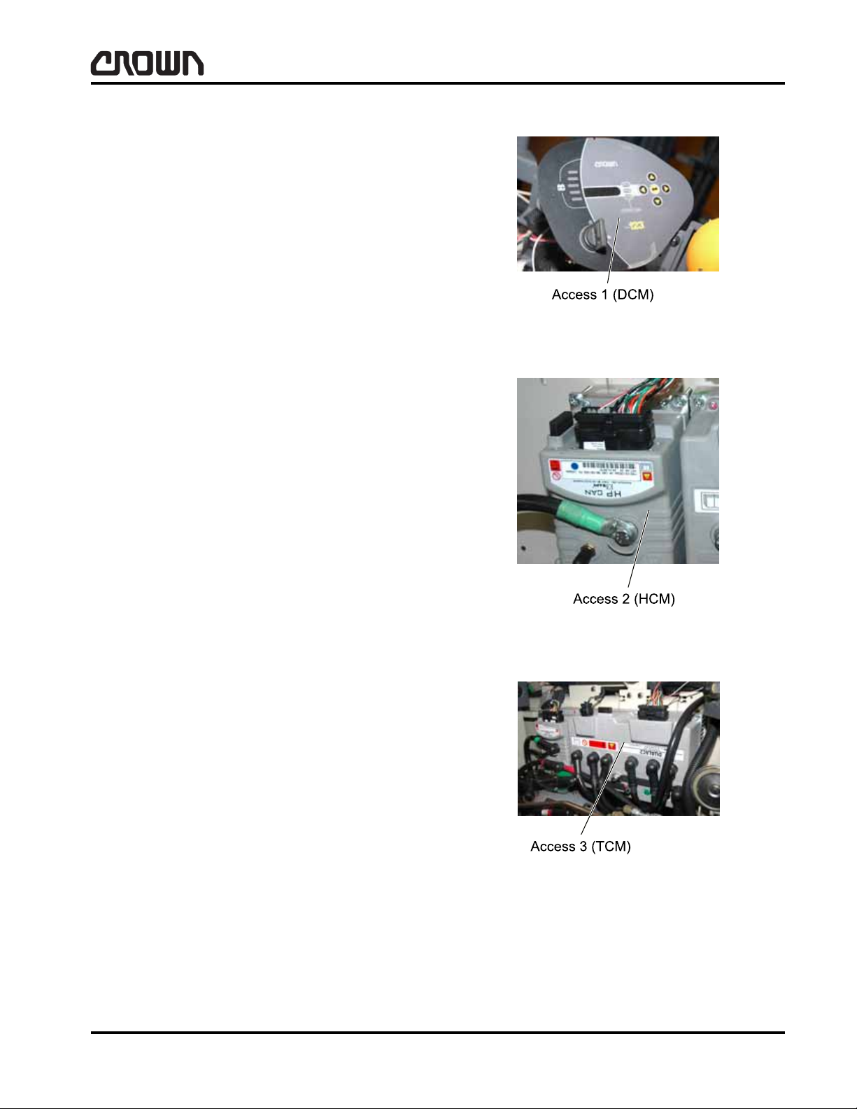
LUBRICATION & ADJUSTMENT
Componentry
Access 1
Display Control Module (DCM)
Location: console (left of multi-task handle).
Purpose: park brake control and displays pertinent
truck information to operator or service technician.
Data: information received from truck control modules
and sensors.
Adjustment: none required.
Access 2
Hydraulic Control Module (HCM)
Location: top of front wall.
Componentry
Figure 15867
Purpose: AC/DC pump motor (M3) control.
Data: information received from truck control modules
and sensors.
Adjustment: none required.
Access 3
Traction Control Module (TCM)
Location: top of front wall.
Purpose: traction motors (M1 & M2) control.
Data: information received from truck control modules
and sensors.
Adjustment: none required.
Figure 15862
Crown 2007 PF15674-1 Rev. 3/07
Figure 15950
M1.0-1055-050
01 Rev. 3/07
45
Page 63
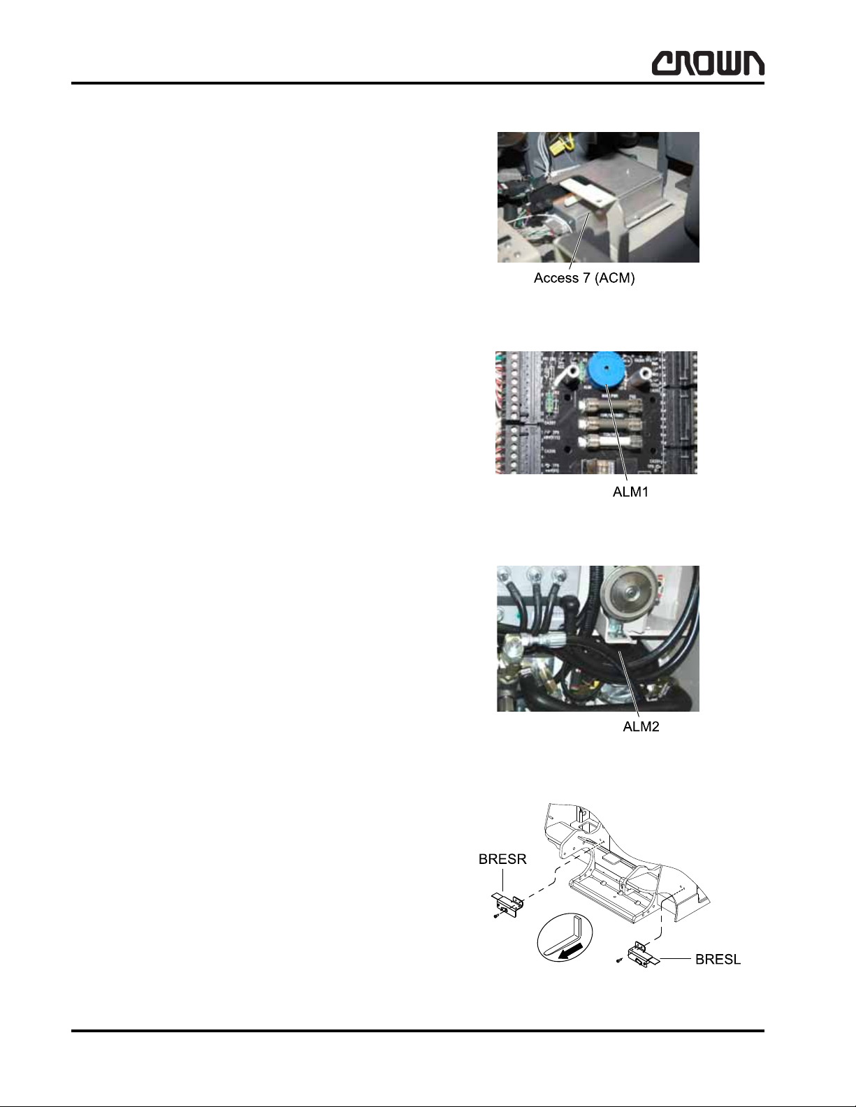
LUBRICATION & ADJUSTMENT
Componentry
Access 7
Accessory Control Module (ACM)
Location: top of power unit, below multifunction con-
trol handle.
Purpose: controls solenoid valve actuations.
Data: information received from truck accesses, multi-
task handle and sensors.
Adjustment: none required.
ALM1
Status Alarm
Location: distribution panel.
Purpose: audible warning when operator doe s incor-
rect sequence (SRO). Also sounded when foot on entry
bar.
Figure 15861
Data: controlled by Access 1.
Adjustment: none required.
ALM2
Travel Alarm
Location: chassis, above oil filter (left side).
Purpose: audible warning when truck is traveling for-
ward and/or reverse direction.
Data: controlled by Access 2.
Adjustment: none required.
BRESL, BRESR
Battery Restraint Switches
Location: cubbies on left/right sides.
Purpose: monitor switch for control system. Informs
control system when battery restraints are in place.
Data: wired normally open - held closed when battery
door is in place.
Figure 16196
Figure 15900
Adjustment: none required.
46
Figure 15866
M1.0-1055-051
Crown 2007 PF15674-2
Page 64

LUBRICATION & ADJUSTMENT
BRKS
Brake Switch
Location: brake pedal mounting bracket on left side.
Purpose: mechanical redundancy of RPS1.
Data: wired normally closed, open when operator de-
presses pedal.
Adjustment: refer to maintenance section.
BRK1
Componentry
Brake Right Hand
Location: bottom center of truck front.
Purpose: park brake, provide 2/3 total braking force.
Data: 18VDC nominal operating voltage.
Adjustment: none required.
BRK2
Brake Left Hand
Location: bottom center of truck front.
Purpose: park brake, provide 1/3 total braking force.
Data: 18VDC nominal operating voltage.
Adjustment: none required.
Figure 15863
Figure 15864
Crown 2007 PF15674-3
Figure 15865
M1.0-1055-052
47
Page 65

LUBRICATION & ADJUSTMENT
Componentry
CBVE
Counterbalance Valve Extend
Location: mast manifold.
Purpose: provide control of overrunning load for tilt
function.
Data: pressure setting pre-set by vendor.
Adjustment: none required.
CBVR
Counterbalance Valve Retract
Location: mast manifold.
Purpose: provide control of overrunning load for tilt
function.
Data: pressure setting pre-set by vendor.
Figure 16046
Adjustment: none required.
Figure 16047
48
M1.0-1055-053
Crown 2007 PF15674-4
Page 66

LUBRICATION & ADJUSTMENT
DMS1, DMS2 and DMS3
CVR
Check Va lve Lower
Location: mast manifold.
Purpose: prevents mast from drifting down (loaded/
unloaded).
Data: allows hydraulic flow in only one direction.
Adjustment: none required.
Componentry
DLS
Dome Light Switch
Location: console.
Purpose: turn on/off dome light.
Data: toggle switch wired normally open.
Adjustment: none required.
DMS1, DMS2, DMS3
Foot Presence Switches
Location: right side of floorboard.
Purpose: indicates right foot presence.
Data: wire normally open - held open wh en nothin g o n
pedal.
Adjustment: none required.
Figure 16048
Figure 15933
Crown 2007 PF15674-5
Figure 15884
M1.0-1055-054
49
Page 67
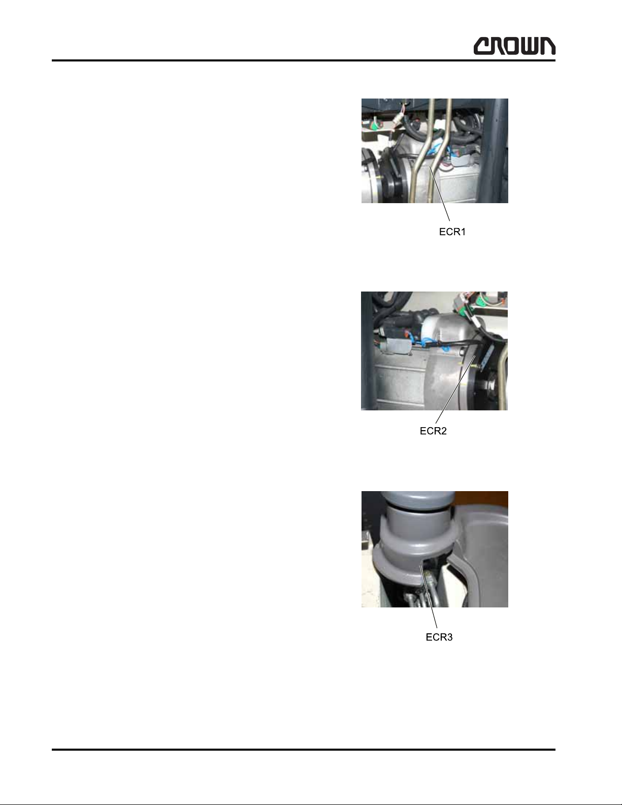
LUBRICATION & ADJUSTMENT
Componentry
ECR1
LH Traction Motor Encoder
Location: inside left hand traction motor.
Purpose: provides speed and direction information to
Access 3 module.
Data: 11.3VDC, 64 pulses per revolution.
Adjustment: none required.
ECR2
RH Traction Motor Encoder
Location: inside right hand traction motor.
Purpose: provides speed and direction information to
Access 3 module.
Data: 11.3VDC, 48 pulses per revolution.
Adjustment: none required.
ECR3
Steering Command Encoder
Location: steer tiller.
Purpose: provide command to Access 7 for steering.
Data: 5VDC, 64 pulses per revolution.
Adjustment: none required.
Figure 15885
Figure 15886
50
Figure 15887
M1.0-1055-055
Crown 2007 PF15674-6
Page 68
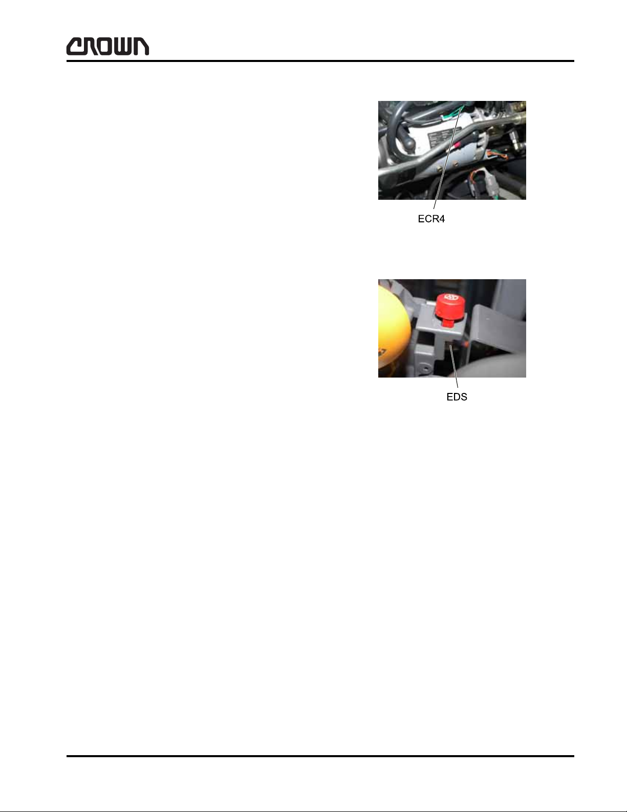
ECR4
AC/DC Pump Motor Encoder
Location: inside AC/DC pump motor.
Purpose: sense AC/DC pump motor speed.
Data: 11.3VDC, 64 pulses per revolution.
Adjustment: none required.
EDS
LUBRICATION & ADJUSTMENT
Componentry
Emergency Disconnect Switch
Location: right side of multi-task handle casting.
Purpose: allows disconnection of power in emergency
situation. Resets the emergency disconnect contactor,
removing power from power/control circuitry.
Data: wired normally closed until operator depresse s
button, then momentarily opens.
Adjustment: none required.
Figure 15888
Figure 15890
Crown 2007 PF15674-7
M1.0-1055-056
51
Page 69

LUBRICATION & ADJUSTMENT
ENLS and ENSR
Componentry
ENLS, ENSR
Entry Bar Switches
Location: left/right sides of entry bar.
Purpose: signals Access 3 to remove power from trac-
tion circuit when operator’s foot is resting on power unit
skirt along operator compartment.
Data: wired normally closed. Oper ator standing on skirt
actuates switch.
Adjustment: none required.
FNS
Fan Switch
Location: console.
Purpose: allows operator to turn on/off operator fan
and select low/high speed.
Figure 15891
Data: Off/high speed/low speed.
Adjustment: none required.
FAN1
Operator Fan
Location: work assist post/A pillar.
Purpose: operator comfort.
Data: 24VDC high speed, 12 volt DC low speed, 1 amp
current draw.
Adjustment: none required.
Figure 15934
Figure 15892
52
M1.0-1055-057
Crown 2007 PF15674-8
Page 70

LUBRICATION & ADJUSTMENT
FAN2
Controller Fan
Location: near bottom side of left A pillar, beside Ac-
cess 3 (TCM).
Purpose: cooling of Access 2 and 3.
Data: 36VDC, 420 mA running current, 3500 rpm and
235 cfm.
Adjustment: none required.
Componentry
FS
Forward Travel Switch
Location: multi-task handle.
Purpose: informs control system forward travel is be-
ing requested by the operator.
Data: Optic switch output 0 volts when forward direc-
tion is selected. Output 5 volts when in neutral or reverse travel selected.
Adjustment: none required.
FU1
Traction Fuse
Location: fuse panel.
Purpose: protect traction motor and associated power
circuitry from overcurrent.
Data: 500A.
Adjustment: none required.
Figure 15893
Figure 15894
Crown 2007 PF15674-9
Figure 15895
M1.0-1055-058
53
Page 71

LUBRICATION & ADJUSTMENT
Componentry
FU2
Hydraulics Fuse
Location: fuse panel.
Purpose: protect hydraulic control circuitry from over-
current.
Data: 400A.
Adjustment: none required.
FU3
Main Power
Location: distribution panel.
Purpose: protect control circuitry from overcurrent.
Data: 15A current.
Figure 15896
Adjustment: none required.
FU4
Options/Tow
Location: distribution panel.
Purpose: protect optional/tow accessories and associ-
ated wiring from overcurrent.
Data: 15A current.
Adjustment: none required.
Figure 15897
Figure 15898
54
M1.0-1055-059
Crown 2007 PF15674-10
Page 72

LUBRICATION & ADJUSTMENT
FU5
TCM
Location: distribution panel.
Purpose: protect Access 2/Access 3 logic circuitry and
associated wiring from overcurrent.
Data: 5A current.
Adjustment: none required.
FU13/FU14
Componentry
Freezer/Corrosion
Location: freeze/corrosion distribution panel.
Purpose: protect freezer condition components and
wiring from overcurrent.
Data: 15A current.
Adjustment: none required.
HGTS1
Height Switch 1
Location: mast at staging.
Purpose: provides speed limit input when forks are
above free lift, provides lift/tilt interlock and reduces
braking deceleration when forks are above free lift.
Data: wired normally closed - held closed when mast is
below staging. 36VDC.
Adjustment: none required.
Figure 16049
Figure 15899
Crown 2007 PF15674-11
Figure 15901
M1.0-1055-060
55
Page 73

LUBRICATION & ADJUSTMENT
Componentry
HGTS2
Height Switch 2
Location: mast at variable heights below staging.
Purpose: provides lift/tilt interlock at specified heights
and specified degrees of tilt for trucks with 10° forward
tilt for Quad/TT.
Data: wire normally closed. Closed when fork carriage
reaches specified heights. 36VDC.
Adjustment: none required.
HGTS3
Height Switch 3
Location: mast at variable heights above staging.
Purpose: provides lift/tilt interlock at specified heights
and specified degrees of tilt for trucks with 10° forward
tilt for Quad/TT.
Data: wire normally closed. Closed when fork carriage
reaches specified heights. 36VDC.
Adjustment: none required.
HGTS4
Height Switch 4
Location: mast at variable heights above staging.
Purpose: provides lift/tilt interlock at specified heights
and specified degrees of tilt for trucks with 10° forward
tilt for TT.
Data: wire normally closed. Closed when fork carriage
reaches specified heights. 36VDC.
Figure 15902
Figure 16240
Adjustment: none required.
01 Rev. 3/07
56
Figure 16241
M1.0-1055-061
Crown 2007 PF15674-12 Rev. 3/07
Page 74
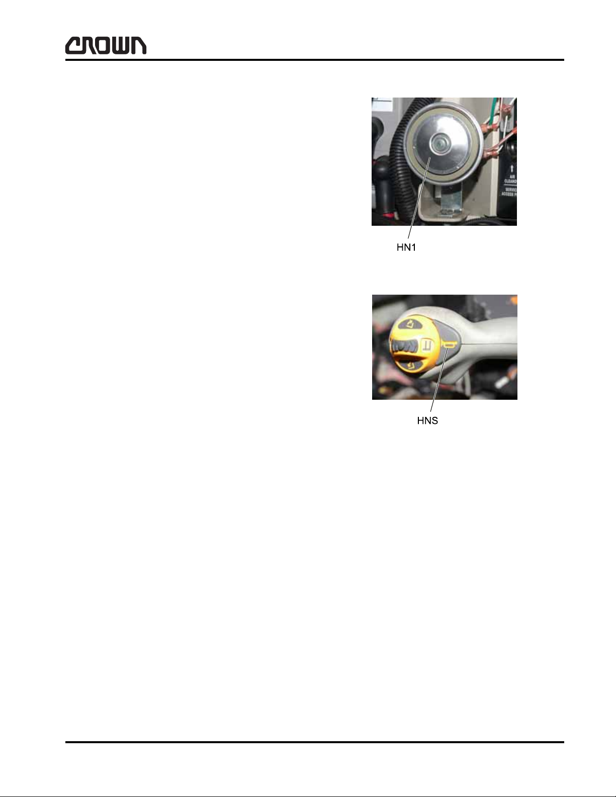
LUBRICATION & ADJUSTMENT
HN1
Horn
Location: bracket by left A pillar.
Purpose: provide operator controlled audible wa rning.
Data: 36VDC, 0.4 amp.
Adjustment: none required.
HNS
Horn Switch
Location: multi-task handle.
Purpose: allow operator to sound horn.
Data: wired normally open until operator depresses
horn button located on multifunction handle.
Componentry
Figure 15903
Adjustment: none required.
Figure 15904
Crown 2007 PF15674-13 Rev. 3/07
M1.0-1055-062
01 Rev. 3/07
57
Page 75

LUBRICATION & ADJUSTMENT
Componentry
K1
Power Up Relay
Location: distribution panel.
Purpose: provides power up, power down sequence
interlock.
Data: 36VDC coil energized upon keyswitch test posi-
tion closure.
Adjustment: none required.
K2
Options
Location: distribution panel.
Purpose: provides power for optional electrical equip-
ment eg. Lights, fan etc.
Data: 36VDC coil energized upon keyswitch test posi-
tion.
Adjustment: none required.
KYS
Key Switch
Location: Access 1 bracket.
Purpose: allows operator to power truck up and shut
truck down by providing battery power to controllers
and power up circuitry.
Data: key operated selector switch. Energizes K1
w/test position and maintains K1 with run position.
Adjustment: none required.
Figure 15906
Figure 15907
01 Rev. 3/07
58
Figure 15908
M1.0-1055-063
Crown 2007 PF15674-14 Rev. 3/07
Page 76

L
Line Contactor
LGT1 and LGT2
Line Contactor
Location: horizontal on contactor panel.
Purpose: switch power to Access 3 power circuitry.
Data: 36VDC.
Adjustment: none required.
LCV
LUBRICATION & ADJUSTMENT
Componentry
Compensated Flow Regulator Lower
Location: mast manifold.
Purpose: limit maximum lowering speed of mast re-
gardless of hydraulic system pressure.
Data: flow setting pre-set by vendor.
Adjustment: none required.
LGT1, LGT2
Work Lights
Location: overhead guard or mast.
Purpose: provide lighted work area outside operator
compartment.
Data: 36VDC.
Adjustment: none required.
Figure 15909
Figure 15905
Crown 2007 PF15674-15 Rev. 3/07
Figure 15910
M1.0-1055-064
01 Rev. 3/07
59
Page 77
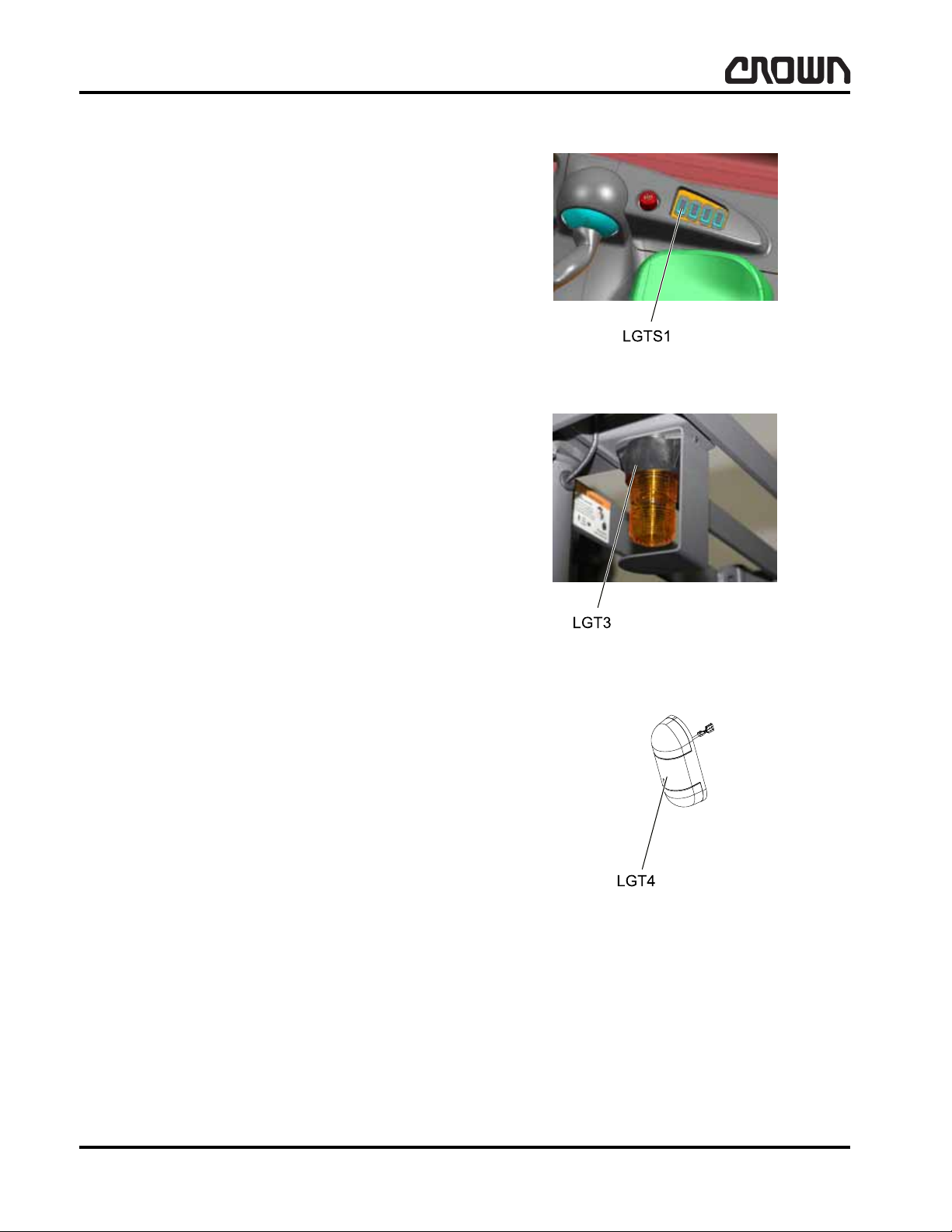
LUBRICATION & ADJUSTMENT
Componentry
LGTS1
Light Switch 1
Location: console.
Purpose: allows operator to turn on/off work assist
lights.
Data: wired normally open - operator toggles switch to
close the contacts and turn on work lights. 36VDC.
Adjustment: none required.
LGT3
Strobe Light
Location: overhead guard.
Purpose: provide visual warning of lift truck presence.
Data: 36VDC.
Adjustment: none required.
LGT4
Dome Light
Location: work assist.
Purpose: provide lighted work area inside operator
compartment.
Data: 12.8VDC, 1.44 amp use 20 ohm resist or in se-
ries with light.
Adjustment: none required.
Figure 15913
Figure 15914
01 Rev. 3/07
60
Figure 15915
M1.0-1055-065
Crown 2007 PF15674-16 Rev. 3/07
Page 78
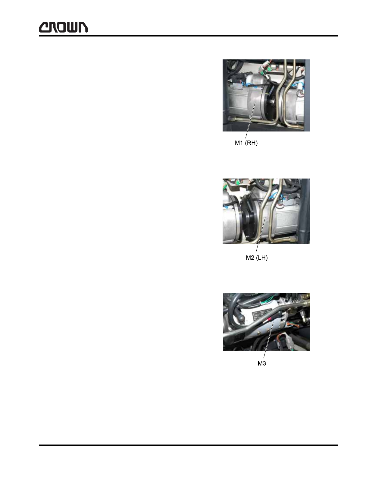
LUBRICATION & ADJUSTMENT
M1
RH Traction Motor
Location: right hand front bottom corner of power unit.
Purpose: provides driving force for traction/regen
braking.
Data: Access 3 provides speed contr ol via o perator in -
put.
Adjustment: none required.
M2
Componentry
LH Traction Motor
Location: left hand front bottom corner of power unit.
Purpose: provides driving force for traction/regen
braking.
Data: Access 3 provides speed contr ol via o perator in -
put.
Adjustment: none required.
M3
AC/DC Pump Motor
Location: front wall of power unit.
Purpose: provide driving force for hydraulic pump sup-
plying hydraulic oil flow for lift and accessory functions.
provides hydraulic pressure for steering/hydraulic functions.
Data: Access 2 provides speed contr ol via o perator in put.
Adjustment: none required.
Figure 15916
Figure 15917
Crown 2007 PF15674-17 Rev. 3/07
Figure 15918
M1.0-1055-066
01 Rev. 3/07
61
Page 79
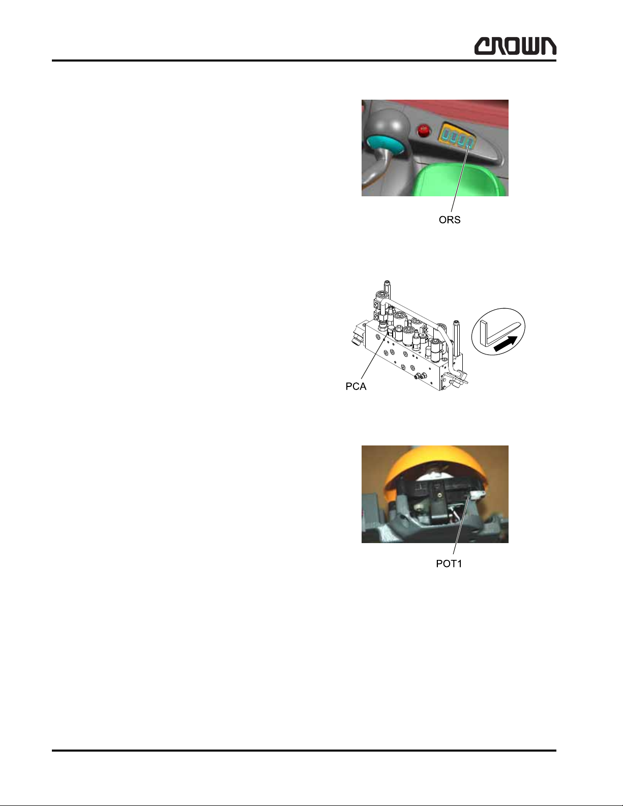
LUBRICATION & ADJUSTMENT
Componentry
ORS
Override (Lift Cutout) Switch
Location: console.
Purpose: allows operator to override height encoder/
limit switch and continue raising.
Data: momentary contact wired normally open - oper-
ator toggles switch to close the contacts and provide
override function.
Adjustment: none required.
PCA
Pressure Compensator Valve
Location: mast manifold.
Purpose: provides priority and compensated flow con-
trol for tilt and accessory functions.
Data: not applicable.
Adjustment: none required.
POT1
Accelerator Potentiometer
Location: multi-task handle.
Purpose: provides input to controller for speed.
Data: 1.7 K ohm.
Adjustment: refer to maintenance section.
Figure 15919
Figure 15940
01 Rev. 3/07
62
Figure 15920
M1.0-1055-067
Crown 2007 PF15674-18 Rev. 3/07
Page 80
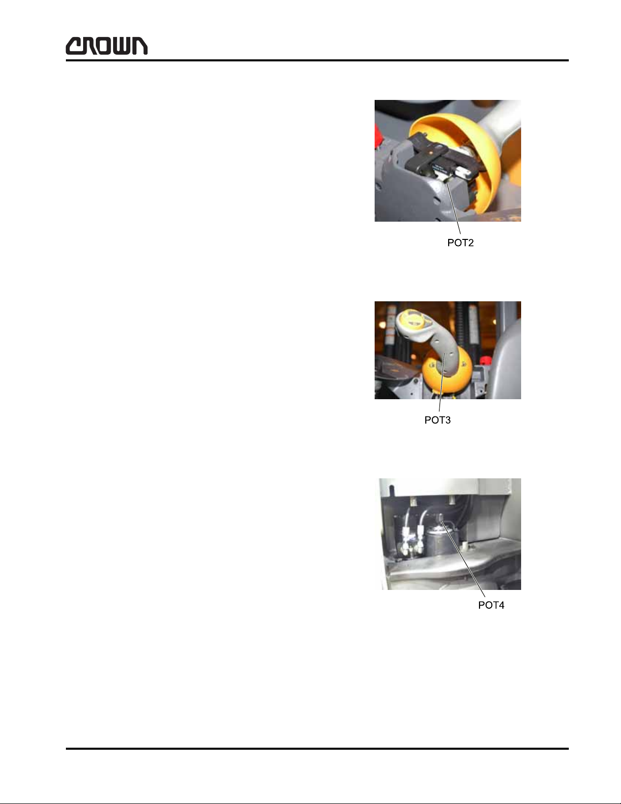
POT2
Lift/Lower Request Potentiomet er
Location: multi-task handle.
Purpose: provide lift request input to controller.
Data: 1.7 K ohm.
Adjustment: refer to maintenance section.
POT3
Accessory Request Potentiometer
LUBRICATION & ADJUSTMENT
Componentry
Location: multi-task handle.
Purpose: provide accessory functions request input to
controller.
Data: 1.7 K ohm.
Adjustment: refer to maintenance section.
POT4
Steer Potentiometer
Location: right of steer tiller.
Purpose: provides input to Access 3 for steering feed-
back.
Data: 5 K ohm.
Adjustment: refer to maintenance section.
Figure 15921
Figure 15922
Crown 2007 PF15674-19 Rev. 3/07
Figure 15923
M1.0-1055-068
01 Rev. 3/07
63
Page 81
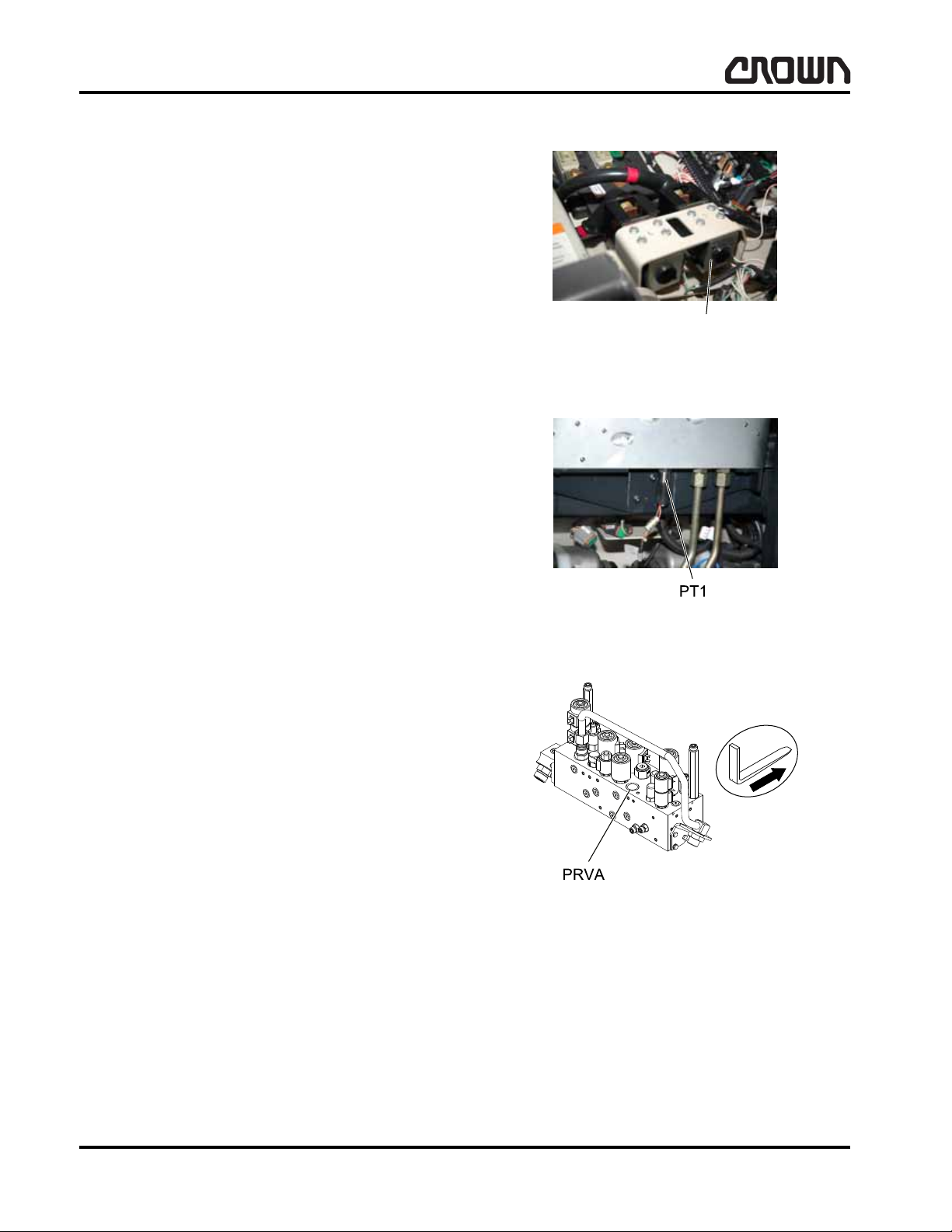
LUBRICATION & ADJUSTMENT
Pump Contactor
Componentry
P
Pump Contactor
Location: horizontal on contactor panel.
Purpose: switch power to Access 2. On/off controlled
by Access 2 via operator input.
Data: 36VDC.
Adjustment: none required.
PT1
Load Sense
Location: bottom side of mast mounted manifold.
Purpose: provides approximate weight measurement
information on forks for data capacity monitor.
Data: bi-directional differential pressure transducer.
Adjustment: none required.
PRVA
Clamp Pressure
Location: mast.
Purpose: replaces RVA valve when truck equipped
with pressure regulator option.
Data: 24VDC maximum.
Adjustment: none required.
Figure 15924
Figure 15925
01 Rev. 3/07
64
Figure 15927
M1.0-1055-069
Crown 2007 PF15674-20 Rev. 3/07
Page 82

LUBRICATION & ADJUSTMENT
RPS1
Rotational Position Sensor 1
Location: bottom side of floorboard.
Purpose: provides input to the Access 3 for braking
command.
Data: 0.5 - 4.5VDC.
Adjustment: none required.
RPS2
Rotational Position Sensor 2
Location: right hand side of tilt cylinder.
Purpose: provides input to Access 7 for tilt cylinder po-
sition.
Data: 0.5 - 4.5VDC.
Componentry
Figure 15929
Adjustment: none required.
RS
Reverse Switch
Location: multi-task handle.
Purpose: informs control system reverse travel being
requested by operator.
Data: optic switch output 0 volt when reverse travel di-
rection selected. Output 5 volt when in neutral or forward travel selected.
Adjustment: none required.
Figure 15930
Crown 2007 PF15674-21 Rev. 3/07
Figure 15931
M1.0-1055-070
01 Rev. 3/07
65
Page 83

LUBRICATION & ADJUSTMENT
Componentry
RV A
Relief Valve Accessory
Location: mast manifold.
Purpose: limit maximum tilt and accessory pressure
(independent from raise).
Data: adjusted to 17237 Kpa (2500 psi) at vendor.
Adjustment: none required.
RVM
Relief Valve Mast
Location: mast manifold.
Purpose: limit maximum lift pressure for raise.
Data: adjusted to 23442 Kpa (3400 psi) at vendor.
Figure 15941
Adjustment: none required.
SSS
Sequence Select Switch
Location: right side of multi-task handle casting.
Purpose: allows 4th and 5th function selection.
Data: printed circuit board mounted push button.
Adjustment: none required.
Figure 15944
Figure 15937
01 Rev. 3/07
66
M1.0-1055-071
Crown 2007 PF15674-22 Rev. 3/07
Page 84
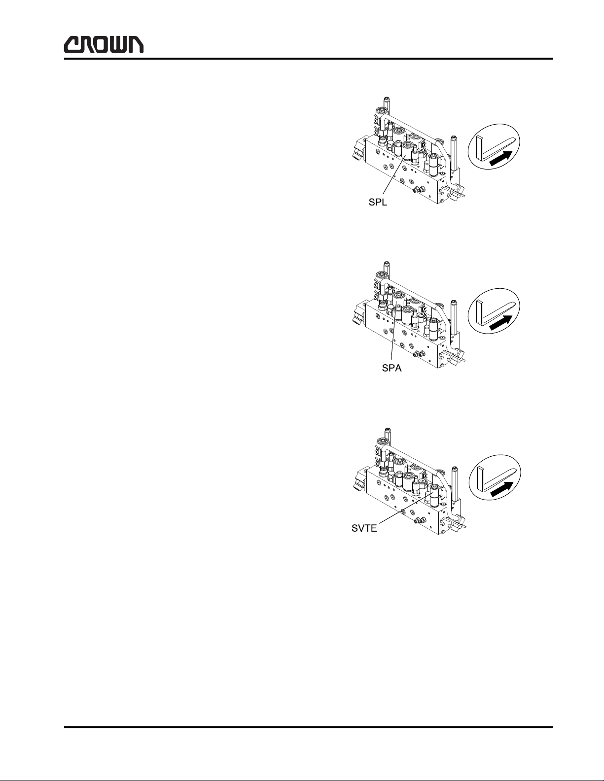
LUBRICATION & ADJUSTMENT
SPL
Load Lowering Proportional Valve
Location: mast manifold.
Purpose: provide hydraulic flow path for the lower
function.
Data: coil energized by Access 7 when lower function
selected via POT2. Coil resistance 28.8 ohm. Coil voltage 24VDC regardless of battery voltage.
Adjustment: none required.
SPA
Auxiliary Proportional Valve
Location: mast manifold.
Purpose: sets hydraulic fluid flow for tilt and accessory
function.
Componentry
Figure 15938
Data: coil energized by Access 7 when accessory
function selected via POT3, SSS o r TDS. Coil resistance 28.8 ohm. Coil voltage 24 volt DC regardless of
battery voltage.
Adjustment: none required.
SVTE
Tilt Extend
Location: mast manifold.
Purpose: tilt retract.
Data: 24 nominal operating voltage.
Adjustment: none required.
Figure 15939
Figure 16053
Crown 2007 PF15674-23 Rev. 3/07
M1.0-1055-072
01 Rev. 3/07
67
Page 85
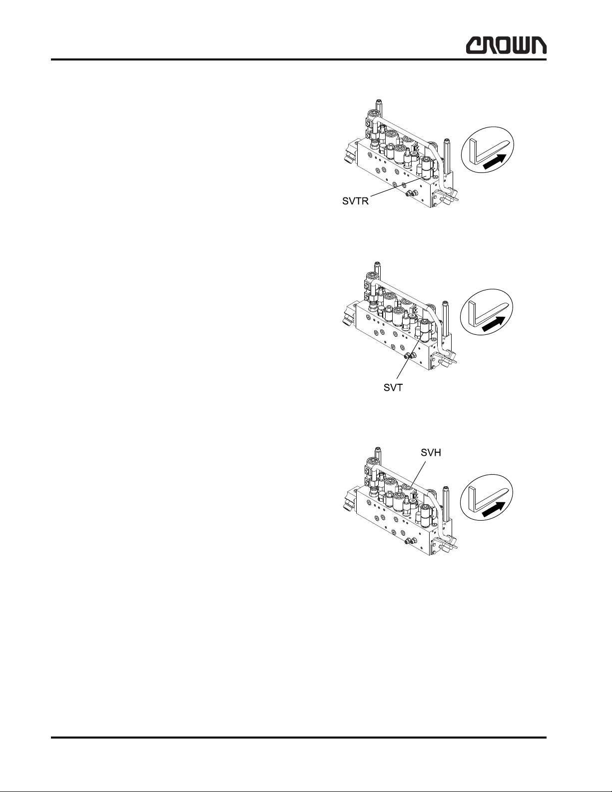
LUBRICATION & ADJUSTMENT
Componentry
SVTR
Tilt Retract
Location: mast manifold.
Purpose: provide hydraulic flow for tilt function.
Data: 24 nominal operating voltage.
Adjustment: none required.
SVT
Tilt Solenoid
Location: mast manifold.
Purpose: provide hydraulic flow direction for tilt func-
tion.
Data: coil energized by Access 7 when tilt function is
selected via TBS or TDS. Coil resistance 39.3 ohms.
Coil voltage 24VDC regardelss of battery voltage.
Figure 16054
Adjustment: none required.
SVH
Hoist Solenoid
Location: mast manifold.
Purpose: provide hydraulic flow path for raise/lower
function.
Data: coil energized by Access 7 when raise function
selected via POT2. Coil resistance 28.8 ohm. Coil voltage 24VDC regardless of battery voltage.
Adjustment: none required.
Figure 15946
Figure 15936
01 Rev. 3/07
68
M1.0-1055-073
Crown 2007 PF15674-24 Rev. 3/07
Page 86
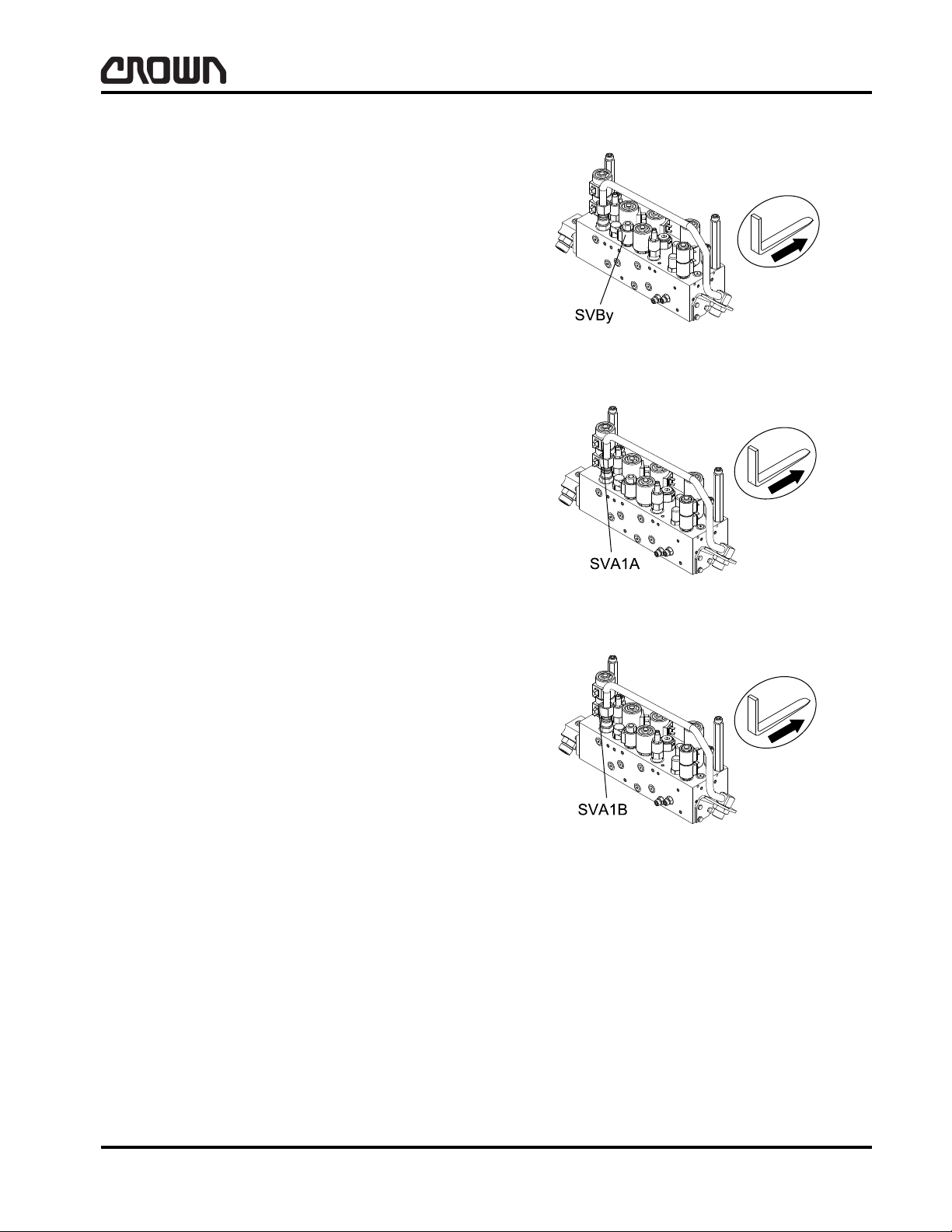
LUBRICATION & ADJUSTMENT
SVBy
Bypass Solenoid
Location: mast manifold.
Purpose: provide hydraulic flow path to reservoir for
excess oil generated while steering.
Data: 24VDC.
Adjustment: none required.
Componentry
SVA1A
First Accessory Solenoid
Location: mast manifold.
Purpose: provide hydraulic flow direction for first ac-
cessory function - right.
Data: coil energized by Access 7 when first accessory
function selected via POT3. Coil resistance 28.8 ohm
for HI flow and 39.3 ohm for LO flow. Coil voltage
24VDC regardless of battery voltage.
Adjustment: none required.
SVA1B
First Accessory Solenoid
Location: mast manifold.
Purpose: provide hydraulic flow direction for first ac-
cessory function.
Data: coil energized by Access 7 when first accessory
function selected via POT3. Coil resistance 28.8 ohm
for HI flow and 39.3 ohm for LO flow. Coil voltage
24VDC regardless of battery voltage.
Figure 15942
Figure 15943
Adjustment: none required.
Crown 2007 PF15674-25 Rev. 3/07
Figure 16055
M1.0-1055-074
01 Rev. 3/07
69
Page 87

LUBRICATION & ADJUSTMENT
Componentry
SVA2A
Second Accessory Solenoid
Location: mast manifold.
Purpose: provide hydraulic flow path for second ac-
cessory function.
Data: coil energized by Access 7 when second acces-
sory function selected via POT3 and pressing SSS at
the same time. Coil resistance 28.8 ohm. Coil voltage
24VDC regardless of battery voltage.
Adjustment: none required.
SVA2B
Second Accessory Solenoid
Location: mast manifold.
Figure 15945
Purpose: provide hydraulic flow path for second accessory function.
Data: coil energized by Access 7 when second accessory function selected via POT3 and pressing SSS at
the same time. Coil resistance 28.8 ohm. Coil voltage
24VDC regardless of battery voltage.
Adjustment: none required.
SVA3
5th Function
Location: part of attachment.
Purpose: 5th function.
Data: none required.
Adjustment: none required.
TBS
Tilt Back Switch
Location: multi-task handle.
Figure 16056
Figure 15947
Purpose: allows operator to select tilt back function of
hydraulic system.
Data: printed circuit board mounted push button switch
wired normally open.
Adjustment: none required.
01 Rev. 3/07
70
Figure 15948
M1.0-1055-075
Crown 2007 PF15674-26 Rev. 3/07
Page 88

LUBRICATION & ADJUSTMENT
TDS
Tilt Down Switch
Location: multi-task handle.
Purpose: allows operator to select tilt down function of
hydraulic system.
Data: printed circuit board mounted push button switch
wired normally open.
Adjustment: none required.
Componentry
TR1
K1 inrush
Location: distribution panel.
Purpose: reduce inrush Access 2/Access 3 power up.
Data: not applicable.
Adjustment: none required.
TR2
KYS inrush
Location: distribution panel.
Purpose: reduce inrush of Access 1 power up.
Data: not applicable.
Adjustment: none required.
Figure 15949
Figure 15951
Crown 2007 PF15674-27 Rev. 3/07
Figure 15952
M1.0-1055-076
01 Rev. 3/07
71
Page 89

LUBRICATION & ADJUSTMENT
Componentry
TS1
RH Traction Motor Thermal
Location: inside right hand traction motor.
Purpose: sense temperature of right hand traction mo-
tor.
Data: temperature compensated diode.
Adjustment: none required.
TS2
LH Traction Motor Thermal
Location: inside left hand traction motor.
Purpose: sense temperature of left hand traction mo-
tor.
Data: temperature compensated diode.
Adjustment: none required.
TS3
Pump Motor Thermal
Location: inside pump motor.
Purpose: sense temperature of pump motor.
Data: temperature compensated diode.
Adjustment: none required.
Figure 15953
Figure 15954
01 Rev. 3/07
72
Figure 15955
M1.0-1055-077
Crown 2007 PF15674-28 Rev. 3/07
Page 90

LUBRICATION & ADJUSTMENT
Grade Marking
(on Head)
Specification Material
Bolt and Screw
Size (mm)
Class 5.8
Class 8.8
Class 10.9
M5 through M36
M5 through M36
M5 through M36
Low Carbon Steel
Medium Carbon Steel
Quenched and Tempered
Medium Carbon Alloy S teel
Quenched and Tempered
NOTE: Even though a bolt head is unmarked, Crown uses noth ing less than class 8.8 in all of it s bolted
assemblies. Instances do occur when class 8.8 bolt s are manufactured unmarked. When a fastener
is replaced that is unmarked, replace the fastener with a class 8.8.
Metric Torque Values
All Crown trucks are manufactured with class 8.8 or
better screws and bolts. The information contained in
this section will aid you when replacing any screws and
bolts that are necessary when performing maintenance
on your lift truck.
Grade
Metric Torque Values
Figure 15048
Crown 1989 PF8514-1 Rev. 11/08
M1.9-06.6-001
02 Rev. 11/08
73
Page 91

LUBRICATION & ADJUSTMENT
Metric Torque Values
Torque Chart - Metric Hex Head Cap Screws and Nuts
Thread Diameter
& Pitch
M5 x 0.80 5 - 8 (4 - 6) 7 - 8 (5 - 6) 8 - 10 (6 - 7)
M6 x 1.00 8 - 10 (6 - 7) 12 - 14 (9 - 10) 15 - 16 (11 - 12)
M8 x 1.25 20 - 25 (15 - 18) 28 - 31 (21 - 23) 34 - 37 (25 - 27)
M10 x 1.50 39 - 43 ( 29 - 32) 56 - 61 (41 - 45) 68 - 75 (50 - 54)
M12 x 1.75 71 - 76 (52 - 56) 100 - 107 (73 - 79) 119 - 127 (88 - 94)
M14 x 2.00 113 - 122 (83 - 90) 159 - 171 (117 - 126) 190 - 205 (140 - 151)
M16 x 2.00 175 - 190 (129 - 140) 247 - 267 (182 - 197) 296 - 320 (218 - 236)
M20 x 2.50 340 357 (251 - 271) 479 - 518 (353 - 382 ) 574 - 621 (423 - 458)
M24 x 3.00 587 - 635 (433 - 468) 824 - 892 (608 - 658) 990 - 1071 (730 - 790)
M30 x 3.50 1175 - 1274 (867 - 940) 1654 - 1792 (1220 - 1322) 1985 - 2150 (1464 - 1586)
Note: T orque values called out in the maintenance section of this manual will t ake precedence over torque
values found on this page.
Torque Chart - Metric Hex Socket Countersink Head Screws
Class 8.8 Class 10.9 Class 12.9
Tightening Torque Nm (ft lb)
Thread Diameter
& Pitch
M5 x 0.80 4 - 7 (3 - 5) 5 - 8 (4 - 6) 7 - 10 (5 - 7)
M6 x 1.00 7 - 10 (5 - 7) 9 - 12 (7 - 9) 11 - 14 (8 - 10)
M8 x 1.25 16 - 19 (12 - 14) 23 - 26 (17 - 19) 27 - 30 (20 - 22)
M10 x 1.50 31 - 34 ( 23 - 25) 45 - 49 (33 - 36) 54 - 58 (40 - 43)
M12 x 1.75 56 - 60 (41 - 44) 79 - 84 (58 - 62) 94 - 102 (69 - 75)
M14 x 2.00
M16 x 2.00 124 - 146 (99 - 108) 190 - 206 (140 - 152) 228 - 247 (168 - 182)
M20 x 2.50 259 - 281 (191 - 207) 363 - 395 (268 - 291) 437 - 473 (322 - 349)
M24 x 3.00 416 - 451 (307 - 333) 586 - 635 (432 - 468) 702 - 762 (518 - 562)
M30 x 3.50
Note: T orque values called out in the maintenance section of this manual will t ake precedence over torque
values found on this page.
Class 8.8 Class 10.9 Class 12.9
Tightening Torque Nm (ft lb)
02 Rev. 11 /08
74
M1.9-06.6-002
Crown 1989 PF8514-2 Rev. 11/08
Page 92

LUBRICATION & ADJUSTMENT
Torque Chart - Metric Socket Head Cap Screws
Metric Torque Values
Thread Diameter
& Pitch
M5 x 0.80 5 - 8 (4 - 6) 7 - 9 (5 - 7) 8 - 11 (6 - 8)
M6 x 1.00 9 - 12 (7 - 9) 12 - 15 (9 - 11) 15 - 18 (11 - 13)
M8 x 1.25 22 - 24 (16 - 18) 30 - 33 (22 - 24) 35 - 38 (26 - 28)
M10 x 1.50 42 - 45 (31 - 33) 58 - 64 (43 - 47) 71 - 76 (52 - 56)
M12 x 1.75 72 - 77 (53 - 57) 102 - 110 (75 - 81) 122 - 132 (90 - 97)
M14 x 2.00 115 - 125 (85 - 92) 161 - 175 (119 - 129) 194 - 210 (143 - 155)
M16 x 2.00 179 - 194 (132 - 143) 251 - 273 (185 - 201) 301 - 327 (222 - 241)
M20 x 2.50 348 - 377 (257 - 278) 489 - 530 (361 - 391) 588 - 637 (434 - 470)
M24 x 3.00 601 - 651 (443 - 480) 846 - 915 (624 - 675) 1014 - 109 8 (748 - 810)
M30 x 3.50 1196 - 1296 (882 - 956) 1681 - 1822 (1240 - 1344) 2017 - 2187 (1488 - 1613)
Note: Torque values called out in the maintenance section of this manual will take precedence over torque
values found on this page.
Torque Chart - Metric Flanged Hex Head Cap Screws and Nuts
Class 8.8 Class 10.9 Class 12.9
Tightening Torque Nm (ft lb)
Thread Diameter
& Pitch
M5 x 0.80 8 - 11 (6 - 8) 9 - 12 (7 - 9)
M6 x 1.00 14 - 16 (10 - 12) 16 - 19 (12 - 14)
M8 x 1.25 31 - 34 (23 - 25) 38 - 41 (28 - 30)
M10 x 1.50 62 - 68 (46 - 50) 75 - 81 (55 - 60)
M12 x 1.75 108 - 117 (80 - 86) 130 - 141 (96 - 104)
M14 x 2.00 174 - 187 (128 - 138) 209 - 225 (154 - 166)
M16 x 2.00 273 - 294 (201 - 217) 327 - 354 (241 - 2610
M20 x 2.50
Note: Torque values called out in the maintenance section of this manual will take precedence over torque
values found on this page.
Class 8.8 Class 10.9 Class 12.9
Tightening Torque Nm (ft lb)
Crown 1989 PF8514-3 Rev. 11/08
M1.9-06.6-003
02 Rev. 11/08
75
Page 93

Notes:
76
Page 94

LUBRICATION & ADJUSTMENT
Grade Marking
(on Head)
Specification Material
Bolt and Screw
Size (Inches)
SAE - Grade 2
SAE - Grade 5
SAE - Grade 8
Low Carbon Steel
Medium Carbon Steel,
Quenched and Tempered
Medium Carbon Alloy Steel,
Quenched and Tempered
1/4 thru 1-1/2
1/4 thru 1-1/2
1/4 thru 1-1/2
NOTE: Even though a bolt head is unmarked, Crown uses nothing less than Grade 5 in all of it s bolted
assemblies. Instances do occur when Grade 5 bolt s a re manufacture d unmarked . When a fa stener is
replaced that is unmarked, replace the fastener with a Grade 5.
Torque Values
All Crown Trucks are manufactured with Grade 5 or
better screws and bolts. The information contained in
this section will aid you when replacing any screws and
bolts that are necessary when performing maintenance
on your lift truck.
Grade
Torque Values
Figure 14916
Crown 1979 PF5067-1 Rev. 9/06
M1.9-14.0-001
04 Rev. 9/06
77
Page 95

LUBRICATION & ADJUSTMENT
Torque Values
Torque Chart
Bolt
Diameter
in ft Ib kgm Nm ft lb kgm Nm
1/4 9 ± 3 1.2 ± .4 12 ± 4 13 ± 4 1.8 ± .5 17.5 ± 5.5
5/16 18 ± 5 2.5 ± .7 24.5 ± 7 25 ± 5 3.5 ± .7 34 ± 7
3/8 32 ± 5 4.4 ± .7 43.5 ± 7 48 ± 10 6.6 ± 1.3 65 ± 13.5
7/16 50 ± 10 6.9 ± 1.4 67.5 ± 13.5 75 ± 10 10.4 ± 1.4 102 ± 13.5
1/2 75 ± 10 10.4 ± 1.4 101.5 ± 13.5 112 ± 15 15.5 ± 2.0 152 ± 20.5
9/16 110 ± 15 15.2 ± 2.0 149 ± 20.5 163 ± 20 22.5 ± 3.0 221 ± 27
5/8 150 ± 20 20.7 ± 2.8 203.5 ± 27 225 ± 30 31.1 ± 4.1 305 ± 41
3/4 265 ± 35 36.6 ± 4.8 359 ± 47.5 400 ± 50 55.2 ± 6.9 542 ± 68
7/8 420 ± 60 58.1 ± 8.3 569 ± 81 640 ± 80 88.3 ± 11.0 868 ± 108
1 640 ± 80 88.5 ± 11.1 868 ± 109 960 ± 115 132.5 ± 15.9 1300 ± 156
1 1/8 800 ± 100 110.6 ± 13.8 1085 ± 136
1 1/4 1000 ± 120 138 ± 16.6 1356 ± 163
1 3/8 1200 ± 150 166 ± 20.7 1630 ± 203
1 1/2 1500 ± 200 207 ± 27.7 2034 ± 271
Dry Torque Requirement Dry Torque Requirement
Grade 5 Grade 8
Mounting bolt torque requirements
involving hydraulic valves.
5/16 13 ± 2 1.8 ± .3 17.5 ± 2.5
3/8 24 ± 2 3.3 ± .3 32.5 ± 2.5
7/16 39 ± 2 5.4 ± .3 53 ± 2.5
NOTE:Torque values called out in the maintenance section of this manual will take prece-
dence over torque values found on this page.
04 Rev. 9/06
78
M1.9-14.0-002
Crown 1979 PF5067-2 Rev. 9/06
Page 96

HYDRAULIC
79
Page 97

Notes:
80
Page 98

HYDRAULIC
WARNING
NOTE
CAUTION
General Information
General Information
The hydraulic system in your truck is powered by a
gear type pump driven by either a DC motor or a three
phase AC motor. The pump, P1, supplies oil flow for
steering, lift and accessory functions.
Maximum pressure is limited by an adjustable relief
valve, RVM. The setting for RVM is noted on the hydraulic schematics. Refer to the service manual index
for pump, valve and manifold information.
AVOID HIGH PRESSURE FLUIDS-Escaping fluid under pressure can penetrate the skin causing serious injury. Relieve pressure before disconnecting hydraulic
lines. Tighten all connections before applying pressure. Keep hands and body away from pin holes which
eject fluids under high pressure. Use a piece of cardboard or paper to search for leaks. Do not use your
hand.
Any fluid injected into the skin under high pressure
should be considered as a serious medical emergency
despite an initial normal appearance of the skin. Ther e
is a delayed onset of pain, and serious tissue damage
may occur. Medical attention should be sought immediately by a specialist who has had experience with this
type of injury.
Reservoir
With all cylinders in the retracted position and after all
air has been bled from the hydraulic system, fill reservoir so that the oil level is to the "FULL" mark on dipstick. The dipstick is located with the breather assembly in reservoir. The capacity of the hydraulic reservoir
at this level should be approximately 16.6 liters
(4.4 gallons).
The hydraulic system is very susceptible to dirt and
contamination that could, over time, create hydraulic
malfunctions. Therefore, bef ore adding oil to tr uck, filter oil with a 10 micron filter or with a 100 mesh str ainer .
This is especially important when oil source is a
55 gallon drum.
Filter
Every 12 months or 2000 hours:
• Clean suction strainer (100 mesh strainer).
• Replace breather cap (includes 10 micron ele-
ment).
• Replace return filter (10 micron element).
When replacing return filter , do not tighten filter with the
use of a wrench. A wrench should only be used for filter
removal.
Hydraulic Lines and Fittings
Blow air through all hose and lines to remove loose
•
particles before installing. Any rubber hose with
wire braid inner construction and any steel tube
lines which have been collapsed or kinke d are permanently damaged and must be replaced even if
the damage is not externally visible.
• Flexible hose must be replaced if it collapses in
normal operating position.
• All hoses and lines are to be clear of any surface or
edge which will cause damaging wear and cut s, or
on which they can become caught.
• All connections are to be leak free.
To install filter, apply a film of hydraulic oil to the seal
and hand tighten until seal contacts filter head. Then
tighten ½ revolution. Check for leaks.
Drift Test
All drift test should be conducted with a capacity load
(refer to serial plate for the rated cap acity of your truck).
The material used for the test load must be evenly
stacked within the limits of a four foot square p allet and
must be secured to the fork carriage with forks spread
to their maximum width.
Lift measurement is to be taken from the tip of the fork
to the floor.
Never stand or work under a suspended load.
Crown 2007 PF15675-1 Rev. 9/09
M2.0-1055-001
03 Rev. 9/09
81
Page 99
HYDRAULIC
NOTE
100% Standard
Hydraulic Oil
50/50 Mix of Standard
and Low-Temp
Hydraulic Oil
General Information
Lift Drift Test
Place maximum load (refer to serial plate for rated capacity of your truck) on forks at rated load center, and
mast tilted back. Elevate the test load above staging
height. Shut off truck. After five minutes, measure the
distance the forks have drifted. Load drift downward
may not exceed 64 mm (2.5 in) over a five minute period.
Tilt Drift Test
Cycle tilt forward and back several times before testing.
Place maximum load at rated load center and elevate
load above staged height. With the mast at vertical
(0 in), the mast and carriage may not drift more than
19.05 mm (0.75 in) during a five minute period, measured at the tilt cylinder rod.
Steering Slip
With truck keyed up, stand or place weight on the pedals and turn the tiller into the stop and hold it against the
stop with 128.8-162.7 Nm (95-120 ft lb) steer force.
Check steer tiller speed for CW and CCW directions,
movement is not to exceed 10 rpm on trucks equipped
with standard oil and 20 rpm on trucks equipped with
freezer oil. If the movement exceeds these ratings, a
need for corrective action as indicated.
Trucks equipped with velocity fuses may experience
staging issues if an insufficient mix of low temperature
oil has been used.
For truck applications operating continually in temperatures at or above 4.4° C (40° F), use 100% standard
hydraulic oil (363504-101) (1). Refer to Figure 16063.
For truck applications operating continually in temperatures in a cool environment with freezer us e, a 50/50
blend of low temperature (363505-101) and standard
hydraulic oil (363504-101) (2) should be used.
The proper mixture of freezer hydraulic oil will ensure
the best and most efficient operation of your Crown
equipment.
Freezer Preparation
Crown trucks may require a mixture of low temperature
hydraulic oil, Crown P/N 363505-101 (3.78 liters
[1 gal]), blended 50% with standard hydraulic oil,
Crown P/N 363504-101 (3.78 liters [1 gal]) when used
in a freezer or cooler. High concentrations of low temperature oil is too thin for most cold storage operations
and therefore could shorten the life of the pump and
cylinder packings if used in higher ambient temperatures.
03 Rev. 9/09
82
Figure 22422
Circuit Operation
The following information contains brief descriptions of
the hydraulic circuits for the various hydraulic functions. Figure 14161 is a reference schematic for these
descriptions and may vary for that which is applicable
to your truck. Refer to hydraulic schematic in the HYD
section of this manual for the schematic of your unit.
M2.0-1055-002
Crown 2007 PF15675-2 Rev. 9/09
Page 100

HYDRAULIC
General Information
1 Lift 6 Return Filter
2 Tilt 7 Breather
3 Accessory 1 8 Reservoir
4 Accessory 2 9 Suction Strainer
5 Steering 10 De-aeration Screen
Crown 2007 PF15675-3
M2.0-1055-003
Figure 14161
83
 Loading...