

Crown PZM-2.5, PZM-11, PZM-10LL, PZM-11LL, PZM-6D Application Manual
...
PZM, PCC, SASS AND BOUNDARIES
© 2000 Crown International, All rights
reserved PZM® , PCC®, SASS® and
DIFFEROID®, are registered trademarks of
Crown International, Inc. Also exported
as Amcron
127018-1
7/00
®
Crown International, Inc
P.O. Box 1000, Elkhart, Indiana 46515-1000
(219) 294-8200 Fax (219) 294-8329
www.crownaudio.com

Contents
Background to boundary microphones 1
How the boundary microphone works 2
The PCC microphone 3
Boundary microphone techniques for recording 4
Boundary microphone techniques for sound reinforcement 8
PZM boundaries 9
The SASS PZM stereo microphone 17
How to use the SASS microphone 20
INTRODUCTION
A boundary microphone is a miniature microphone
designed to be used on a surface such as a piano lid,
wall, stage floor, table, or panel. Mounting a miniature
mic on a surface gives several benefits:
• A clearer, more natural sound quality
• Extra sensitivity and lower noise
• Consistent tone quality anywhere around the
microphone
• Natural-sounding pickup of room reverberation
Crown boundary microphones include the PZM, PCC,
MB, and SASS series microphones. This guide explains
how they work and how to use them. For information
on the CM, GLM, and LM models, please see the Crown
Microphone Application Guide.
BACKGROUND
In many recording and reinforcement applications,
the sound engineer is forced to place microphones near
hard reflective surfaces. Some situations where this
might occur are recording an instrument surrounded
by reflective baffles, reinforcing drama or opera with the
microphones near the stage floor, or recording a piano
with the microphone close to the open lid.
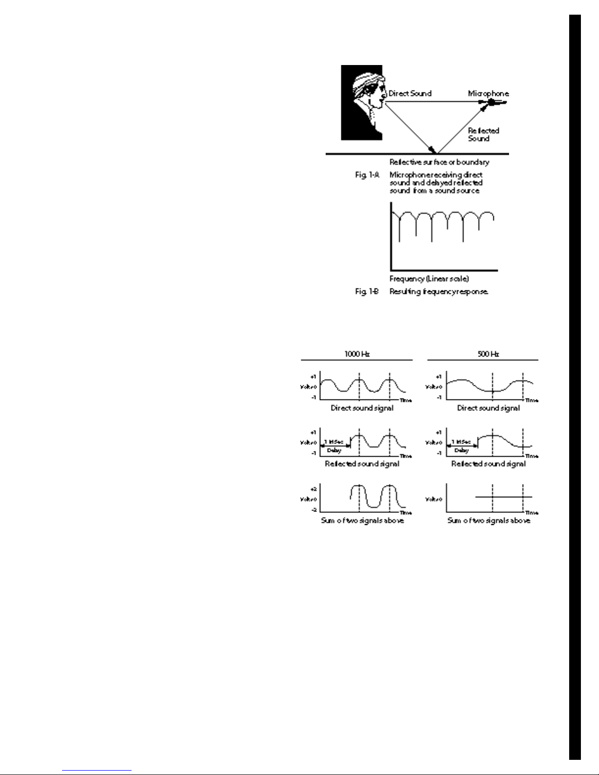
When a microphone is placed near a reflective surface,
sound travels to the microphone via two paths: (1) directly from the sound source to the microphone, and
(2) reflected off the surface (as in Fig. 1-A). Note that
the reflected sound travels a longer path than the direct
sound, so the reflected sound is delayed relative to the
direct sound. The direct and delayed sounds combine
at the microphone diaphragm.
All frequencies in the reflected sound are delayed by the
same time. Having the same time delay for all frequencies creates different phase delays for each frequency,
because different frequencies have different wavelengths. For example, a time delay of 1 millisecond
causes a 360-degree phrase shift for a 1000-Hz wave,
but only a 180-degree phase shift for a 500-Hz wave.
Fig. 2 illustrates this point.
At frequencies where the direct and delayed sounds are
in-phase (coherent), the signals add together, doubling
the pressure and boosting the amplitude 6 dB. At frequencies where the direct and delayed signals are outof-phase, the signals cancel each other, creating a dip
or notch in the response. There results a series of peaks
and dips in the net frequency response called a comb-
filter effect , so named because the response looks like
the teeth of a comb. (Fig. 1-B).
This bumpy frequency response colors the tonal reproductions, giving an unnatural sound. To solve this prob-
Fig. 1
Fig. 2 - Example of wave addition and
cancellation at two different frequencies.
lem, we need to shorten the delay of the reflected sound
so that it arrives at the microphone at the same time the
direct sound does.
If the microphone is placed on the reflective surface (as
in Fig. 3), the direct and reflected sound paths become
nearly equal. There is still a short delay in the reflected
sound because the center of the microphone diaphragm
(where the two sound paths combine) is slightly above
the surface. Consequently, the high frequencies may be
cancelled, giving a dull sound quality.
1

HOW THE BOUNDARY
MIC WORKS
By orienting the diaphragm parallel with the boundary
(as in Fig. 4), the diaphragm can be placed as close to
the boundary as desired. Then the direct and reflected
waves arrive simultaneously at the microphone sound
entry (the slit between the microphone diaphragm and
the boundary). Any phase cancellations are moved outside the audible band, resulting in a smooth frequency
response.
response is not severely degraded.
The Pressure Zone can be defined another way: The
Pressure Zone is the distance from the boundary that
the microphone diaphragm must be placed to achieve
the desired high-frequency response. The closer the
diaphragm is placed to the boundary (up to a point),
the more extended is the high-frequency response.
Let’s show some examples.
For a frequency response down a maximum of 6 dB
at 20 kHz, the mic-to-boundary spacing should be .11."
Or you could say the Pressure Zone is .11" thick. This
spacing corresponds to
1
⁄6 wavelength at 20 kHz.
For a response down 3 dB maximum at 20 kHz, the
spacing should be .085" (
1
⁄8 wavelength at 20 kHz).
For a response down 1 dB maximum at 20 kHz, the
spacing should be .052" (
1
⁄13 wavelength at 20 kHz).
Note that the thickness of the Pressure Zone is an arbitrary number depending on frequency. For example,
the direct and reflected waves of a 100-Hz tone are
effectively in-phase within a Pressure Zone 10" thick.
The Crown PZM microphone-to-boundary spacing
is only .020", which relates to 1 dB down at 52 kHz.
Pressure doubling
As stated earlier, comb-filtering is eliminated when the
direct and reflected waves add together in-phase. There
is another benefit: the sound pressure doubles, giving a
6 dB increase in acoustic level at the microphone. Thus
the effective microphone sensitivity increases 6 dB, and
the signal-to-noise ratio also increases 6 dB.
Consistent tonal reproduction
independent of source height
The microphone placements shown in Figs. 1 and 3
cause another problem in addition to rough response.
As the sound source moves up or down relative to the
surface, the reflected path length changes, which varies
the comb-filter notch frequencies. Consequently, the effective frequency response changes as the source moves.
But with the PZM, the reflected path length stays equal
to the direct path length, regardless of the sound-source
position. There is no change in tone quality as the
source moves.
Lack of off-axis coloration
Yet another problem occurs with conventional microphones: off-axis coloration. While a microphone may have
a flat response to sounds arriving from straight ahead
(on-axis), it often has a rolled-off or colored response to
sounds arriving from other directions (off-axis).
That fault is mainly due to the size of the microphone
and its forward orientation. When sound strikes the microphone diaphragm on-axis, a pressure boost occurs at
The technique of mounting a microphone in this manner is called the Pressure Recording Process
TM
(invented
by Ed Long and Ron Wickersham). They developed the
first microphone to use this process. The first manufactured microphone using the principle was the Pressure
Zone Microphone
®
(developed by Ken Wahrenbrock).
PZM
®
s are now manufactured by Crown International,
the first company licensed to the build microphones
using the Pressure Recording Process.
The Pressure Zone is the region next to the boundary
where the direct and reflected waves are in-phase (or
nearly so). There may be a slight phase shift between
the direct and reflected waves, as long as the frequency
2
Fig. 3 - Conventional microphone on floor receiving
direct sound and slightly delayed reflected sound.
Fig. 4

frequencies where the wavelength is comparable to
the microphone diameter (usually above about 10 kHz).
This phenomenon is called diffraction. Sounds approaching the microphone from the sides or rear,
however, do not experience a pressure boost at high
frequencies. Consequently, the high-frequency response
is greater on-axis than off-axis. The frequency response
varies with the position of the sound source.
Since the PZM capsule is very small, and because all
sound enters the capsule through a tiny, radially symmetric slit, the response stays constant regardless of the
angle at which sound approaches the microphone. The
effective frequency response is the same for sounds
from the front as it is for sounds from other directions.
In other words, there is little or no off-axis coloration
with the PZM. The reproduced tone quality doesn’t
change when the sound source moves.
As further benefit, the PZM has an identical frequency
response for random-incidence sound as it has for direct sound. Direct sound is sound traveling directly
from the source to the microphone; random incidence
sound is sound arriving from all directions randomly.
An example of random-incidence sound is ambience
or reverberation – sounds reflected off the walls, ceiling,
and floor of the recording environment.
With most conventional microphones, the response
to reverberant, random-incidence sound is rolled off in
the high frequencies compared to the response to direct
sound. The direct sound may be reproduced accurately,
but the reproduced reverberation may sound duller
than in real life.
This fact leads to some problems in recording classical
music with the microphones placed far enough away to
pick up concert-hall ambience. The farther from the
sound source the microphone is placed, the more reverberant is the sound pickup, and so the duller the sound
is. The effective microphone frequency response may
become duller (weaker in the high frequencies) as the
microphone is placed farther from the sound source.
This doesn’t occur with the PZM when it’s used on the
floor. The effective response stays the same regardless
of the mic-to-source distance. The response to ambient
sound (reverberation) is just as accurate as the response
to the direct sound from the source. As a result, the total
reproduction is brighter and clearer.
Reach
“Reach” is the ability to pick up quiet distant sounds
clearly. “Clearly” means with a high signal-to-noise ratio, a wide smooth frequency response, and a high ratio
of direct sound to reverberant sound.
As described earlier; the PZM has several performance attributes that contribute to excellent reach. The signal-to-
noise ratio is high because the signal sensitivity is boosted
6 dB by the on-surface mounting. The frequency response
is wide and smooth because comb filtering is eliminated,
and because reverberant sound is picked up with a full
high-frequency response. The direct-to-reverberant sound
ratio is high because the direct sound is boosted 6 dB near
the surface, while the reverberant sound, being incoherent,
is boosted only about 3 dB.
If the PZM element is mounted in a corner, the direct sound
is boosted 18 dB, while reverberant sound is boosted only
9 dB. This gives the PZM a 9 dB advantage over a conventional omnidirectional microphone in the ratio of direct-toreverberant sound. In other words, distant sources sound
closer and clearer with the PZM than they do with a conventional omnidirectional microphone.
Low vibration sensitivity
The low mass and high damping of the PZM diaphragm
make it relatively insensitive to mechanical vibrations
such as table and floor thumps and clothing noise.
The only pickup of theses sounds is acoustic pickup
through the air, not mechanical pickup through the
microphone housing.
Small size
In addition to the acoustic benefits of the PZM, there are
psychological benefits related to its low-profile design.
Its inconspicuous appearance reduces “mic fright.” Since
the PZM does not point at the performers, they may feel
more relaxed in not having to aim their instruments at
the microphone.
PZMs can be hidden in theatre sets. In TV-studio applications, the PZM practically disappears on-camera.
PZMs reduce clutter on the conference tables and lecterns, giving the feeling that no microphones are in use.
THE PCC
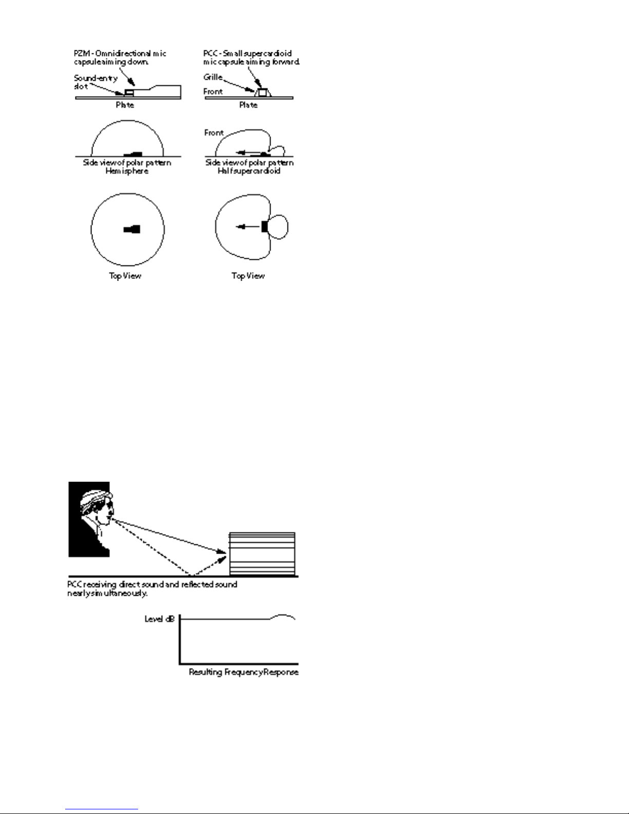
The Phase Coherent Cardioid (PCC) is a surfacemounted supercardioid microphone which provides
the same benefits previously mentioned for the PZM.
Unlike the PZM, however, the PCC uses a subminiature
supercardioid mic capsule. Its directional polar pattern
improves gain-before-feedback, reduces unwanted room
noise and acoustics, and rejects sound from the rear.
Fig. 5 shows the difference in construction and polar
patterns of the PZM and PCC.
In the Crown PCC, the microphone diaphragm is small
enough so that any phase cancellations are above the
audible range (Fig. 6). This results in a wide, smooth frequency response free of phase interference. In contrast,
the mic capsules in conventional microphones are relatively large. As a result, reflections are delayed enough to
cancel high frequencies, resulting in dull sound (Fig. 3).
3
BOUNDARY MICROPHONE
TECHNIQUES FOR RECORDING
Before placing microphones, work on the “live” sound
of the instrument or ensemble to be recorded. Do what
you can to improve its sound in the studio.
To determine a good starting microphone position, close
one ear with your finger; listen to the instrument with
the other, and move around until you find a spot that
sounds good. Put the PZM there, or put it on the floor
or table at that distance.
Moving the microphone around the instrument will
vary the tone quality, because an instrument radiates a
different spectrum in every direction. Place the PZM to
get the desired tone quality, then use equalization only
if necessary. Note that the response of the PZM does not
change with the angle of incoming sound, but the spectrum of the instrument does change depending on how
it is aimed at the PZM.
To reduce pickup of acoustics, leakage from other instruments and background noise, move the PZM closer
to the sound source. Mike only as close as necessary,
since too-close placement may result in an unnatural
tonal balance. Move the PZM farther from the source
to add ambience or “artistic leakage” to the recording.
To further reduce pickup of unwanted sounds, mount
the PZM on a large baffle or acoustic panel placed between the PZM and the offending noise source.
Use the smallest number of microphones that provide
the desired sound; use as few as necessary. Sometimes
this can be done by covering several sound sources with
a single microphone. The wide polar pattern of the PZM
allows you to pick up several instruments or vocalists on
a single microphone with equal fidelity.
Follow the 3:1 rule: When multiple microphones are
mixed to the same channel, the distance between the
microphones should be at least three times the micto-source distance. This procedure reduces phase interference between the microphones. For example, if two
microphones are each placed 2 feet from the instruments
they cover, the mics should be at least 6 feet apart.
PZMs used in multiple-microphone applications may
pick up a lot of leakage (“off-mic” sounds from other instruments). This leakage usually sounds good, however,
owing to the PZM’s uncolored off-axis response. Artistic
usage of leakage can add pleasing “liveliness” to the recording.
When a PZM is mounted on a wall, the wall becomes
a part of the microphone. When a PZM is mounted in
a corner, then all three walls become part of the microphone. The Pressure Zones of all the walls combine to
reinforce the sound pickup. Use this fact to your advantage by mounting the PZM capsule at the junction of
multiple boundaries whenever possible.
Fig. 5
4
Technically, the PCC is not a Pressure Zone Microphone.
The diaphragm of a PZM is parallel to the boundary;
the diaphragm of the PCC is perpendicular to the
boundary. Unlike a PZM, the PCC “aims” along the
plane on which it is mounted. In other words, the main
pickup axis is parallel with the plane.
Because of its supercardioid polar pattern, the PCC has
nearly a 6 dB higher direct-to-reverberation ratio than
the PZM; consequently, distant sources sound closer and
clearer with the PCC than with the PZM.
Fig. 6

The following are some guidelines for PZM placement
in various recording applications. Many were provided
by users. Although these techniques have worked well
in many situations, they are just suggestions.
Acoustic guitar, mandolin, dobro,
banjo:
• On panel in front, about 2 feet away, guitar height.
• On panel in front and overhead to avoid interference
with audience viewing.
• On floor (for soloist).
String section:
• On panel above and in front of the entire section.
• On panel midway between two instruments, about
6 feet high.
Fiddle or Violin:
• On panel in front or overhead.
• On music stand.
Cello or acoustic bass:
• On panel on floor, in front, tilted toward performer.
• On panel in front and above.
• On floor (for soloist).
String quartet:
• Spaced pair on floor about 3 to 6 feet apart.
• Spaced pair on panels in front and above, spaced
3 to 6 feet apart.
Harp:
• On panel about 2 1⁄2 feet away, aiming toward treble
part of sound board.
Sax, flute, clarinet:
• On panel in front and slightly above.
• On music stand.
Horns, trumpet, cornet, trombone:
• On wall, on hard-surface gobo, or on control-room
window. Performers play to the wall or gobo a few feet
away. Since their sound bounces off the wall back to
them, they can hear each other well enough to produce
a natural acoustic balance.
• On panel in front of and between every two players,
1 to 2 feet away.
• On music stand.
• Tuba – on panel overhead.
Grand Piano:
• Tape a PZM to the underside of the lid in the middle
(Fig. 7). Put the lid on the long stick for best sound
quality. To reduce leakage and feedback, put the lid on
the short stick or close the lid and cover the piano with
a heavy blanket.
• For stereo, use two PZMs taped under the lid – one
over the treble strings near the hammers, one over the
bass strings well away from the hammers. Microphone
placement close to the hammers emphasizes attack;
placement far from the hammers yields more tone.
• To pick up the piano and room ambience with a single
microphone, place a PZM on a panel about 6 to 8 feet
from the piano, 4 feet high. Put the lid on the long stick,
and face the panel at the piano with the panel perpendicular to the lid.
• To add ambience to a close-miked piano, mix in a PZM
or two placed on a wall far from the piano.
• For singers who accompany themselves on a piano,
mount two PZMs on opposite sides of a panel. Place the
panel about where the music rack would be. For stereo,
use a longer panel with two microphones on each side
of the panel.
Amplifier/speaker for electric guitar,
piano, bass:
• On panel in front of amp.
• On floor a few feet in front of amp. For an interesting
coloration, add a panel a few feet behind the microphone.
• Inside the cabinet.
Leslie organ cabinet:
• Two PZMs on either side of the rotating horn, inside the
top of the cabinet. Place another PZM inside the bottom cabinet.
Drum set:
• On panel or hard gobo, 1 to 2 feet in front of set, just
above the level of the tom-toms. Use two microphones
3 feet apart for stereo. The drummer can balance the
sound of the kit as he or she plays. Also hang a smallplate PZM vertically in the kick drum facing the beater
head, with a pillow or blanket pressing against the
beater head. The high sound pressure level will not
cause distortion in the PZM’s signal.
• Try two PZMs overhead, each mounted on a 1-foot
square panel, angled to form a “V,” with the point of the
“V” aiming down. Omit the panel for cymbal miking.
• Two PZMs on a hard floor, about 2 feet to the left and
right of the drummer.
• Tape a PZM to a gauze pad and tape the pad to the kick
drum beater head near the edge. This mic will also pick
up the snare drum.
• See percussion below.
Fig. 7
5
 Loading...