

Crown Pulse 2-X-1100 Owners manual
Professional Power Amplifier
User Manual

Contents
Safety Information .................................................................................. 3
1.0 Introduction & Unpacking .................................................................... 4
2.0 Mechanical Installation ........................................................................ 5
3.0 AC Power Connection ......................................................................... 6
4.0 Audio Connections ............................................................................. 7
Inputs .............................................................................................................7
Outputs...........................................................................................................8
Stereo operation............................................................................................................ 8
Bridge mono operation ....................................................................................................8
5.0 Control operation .............................................................................. 9
a. Power Switch ................................................................................................9
b. Level controls 1 and 2...................................................................................... 9
c. Bridge switch ................................................................................................9
6.0 Indicators........................................................................................10
A. AC Present ................................................................................................. 1 0
B. Operate..................................................................................................... 10
C. Fault ........................................................................................................ 10
D. Temp 1&2 .................................................................................................. 1 0
E. Signal........................................................................................................ 1 0
F. Clip........................................................................................................... 11
G. Bridge ....................................................................................................... 1 1
7.0 Typical applications ...........................................................................12
a. Two channel (stereo) operation ........................................................................ 1 2
b. Two amplifiers used in bridge mode................................................................... 12
c. Two amplifiers for stereo with a mono sub-bass .................................................... 13
d. Calculating Impedance ................................................................................... 13
8.0 Glossary..........................................................................................14
9.0 Specifications ..................................................................................17
10.0 Troubleshooting .............................................................................. 18
Checklist ....................................................................................................... 18
Status Indication.............................................................................................. 1 9
11.0 Service & Warranty ..........................................................................20
2

Safety Information
Important Safety Instructions
1) Read these instructions.
2) Keep these instructions.
3) Heed all warnings.
4) Follow all instructions.
5) Do not use this apparatus near water .
6) Clean only with a dry cloth.
7) Do not block any ventilation openings. Install in
accordance with the manufacturer’ s instructions.
8) Do not install near any heat sources such as radiators,
heat registers, stoves, or other apparatus that produce
heat.
9) Do not defeat the safety purpose of the polarized or
grounding-type plug. A polarized plug has two blades
with one wider than the other . A grounding-type plug has
two blades and a third grounding prong. The wide blade
or the third prong is provided for your safety. If the
provided plug does not fit into your outlet, consult an
electrician for replacement of the obsolete outlet.
10) Protect the power cord from being walked on or pinched,
particularly at plugs, convenience receptacles, and the
point where they exit from the apparatus.
11) Only use attachments/accessories specified by the
manufacturer.
12) Use only with a cart, stand, bracket, or table specified
by the manufacturer , or sold with the apparatus. When a
cart is used, use caution when moving the cart/
apparatus combination to avoid injury from tip-over .
13) Unplug this apparatus during lightning storms or when
unused for long periods of time.
14) Refer all servicing to qualified service personnel.
Servicing is required when the apparatus has been
damaged in any way , such as power-supply cord or plug is
damaged, liquid has been spilled or objects have fallen
into the apparatus, the apparatus has been exposed to
rain or moisture, does not operate normally , or has been
dropped.
DO NOT REMOVE COVERS. NO USER
SERVICEABLE P ARTS INSIDE.
REFER SERVICING T O QUALIFIED SERVICE
PERSONNEL.
THIS EQUIPMENT MUST BE GROUNDED. IT
SHOULD NOT BE NECESSAR Y T O REMOVE ANY
PROTECTIVE GROUND OR SIGNAL CABLE
SHIELD CONNECTIONS T O PREVENT GROUND
LOOPS. ANY SUCH DISCONNECTIONS ARE
OUTSIDE THE RECOMMENDED PRACTICE OF
CROWN AND WILL RENDER ANY EMC OR
SAFETY CERTIFICATION VOID.
For continued compliance with international
EMC legislation ensure that all input cables are
wired with the cable screen connected to Pin 1
of the XLR connectors and/or the jack plug
sleeve.
WARNING!
This equipment can create
high sound levels. Exposure
without adequate protection
could cause permanent
damage to hearing.
This equipment has been tested and found to comply with the following European and international Standards
for Electromagnetic Compatibility and Electrical Safety:
Radiated Emissions (EU): EN55013 (1990) Associated Equipment
RF Immunity (EU): EN50082/1 (1992) RF Immunity, Fast Transients & ESD
Mains Disturbance (EU): EN61000/3/2 (1995)
Electrical Safety (EU): EN60065 (1993)
Radiated Emissions (USA): FCC part 15 Class B
3
1.0 Introduction & Unpacking
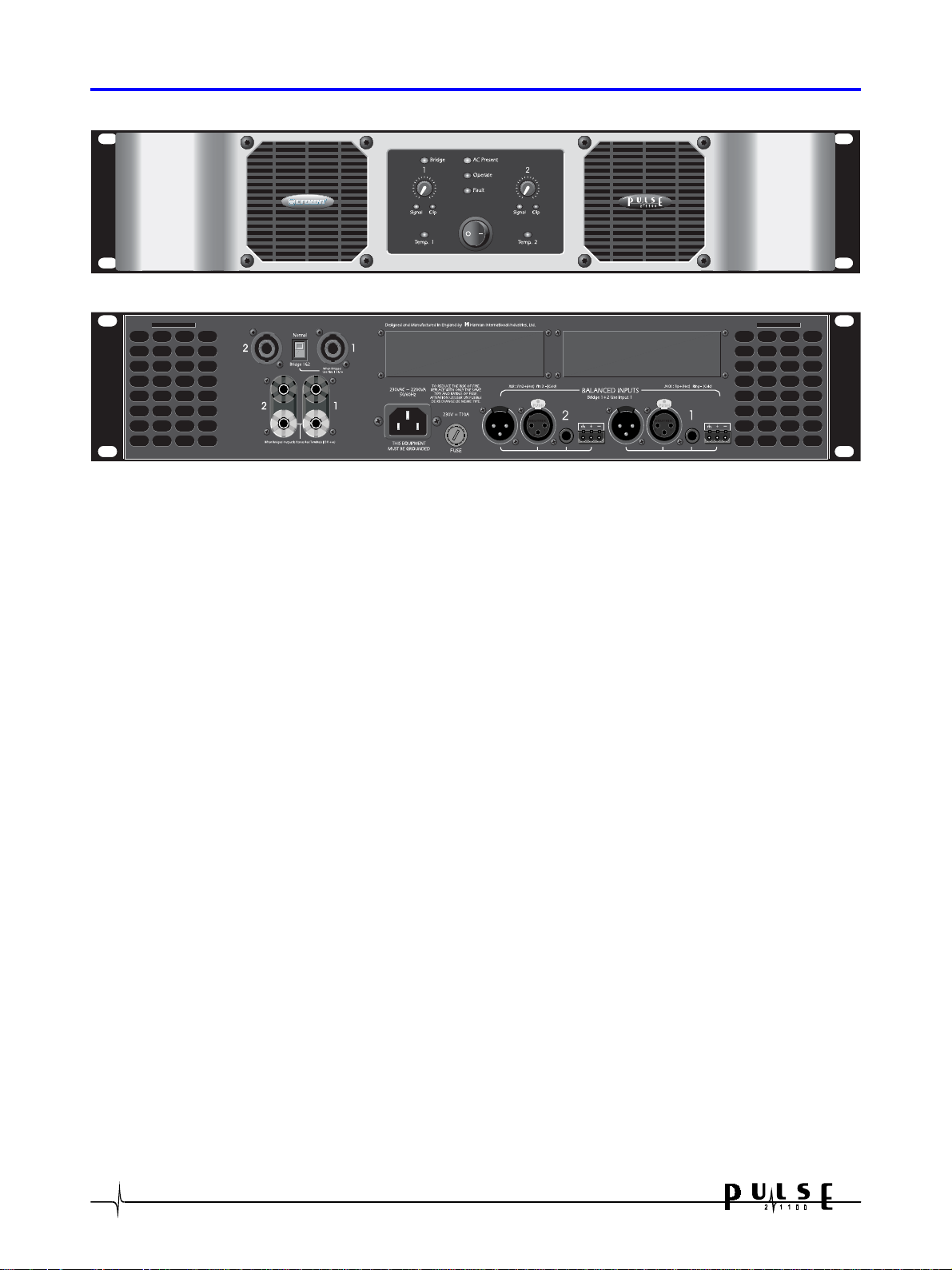
Front panel
Rear panel
Introduction
The PULSE series of amplifiers are high performance professional power amplifiers capable of delivering
major power output from a new generation of switched mode power supplies. All Pulse series amplifiers are
housed in the same size 2U cases and feature light, powerful switching power supplies along with massive
heatsinks and two dual-speed cooling fans. Microprocessor supervision of the power supplies, protection and
thermal systems, ensures that the amplifier is always operating correctly thereby protecting both the
amplifier and your speakers from failure.
We set out to design an amplifier that is as equally at home in live touring sound environments as it is for
installation amplification. We especially wanted to produce amplifiers that are capable of maintaining
excellent performance when being driven to their limit with real loudspeaker loads.
Sonic performance is always in the forefront of our minds and to this end the PULSE series represents the
pinnacle of many years work with professional amplifiers. PULSE amplifiers have impeccable technical
specifications, and extensive listening tests by many people with a wide variety of loudspeakers leads us to
believe that they sound pretty good too!
Unpacking
As part of the Crown system of quality control, we check every product carefully before packing to ensure
that it reaches you in flawless condition.
Before you go any further, please check the unit for any physical damage and retain the shipping carton and
all relevant packing materials for use, should the unit need returning.
In the event that damage has occurred, please notify your dealer immediately, so that a written claim to
cover the damages can be initiated. Check out the Service and W arranty section for more information.
4
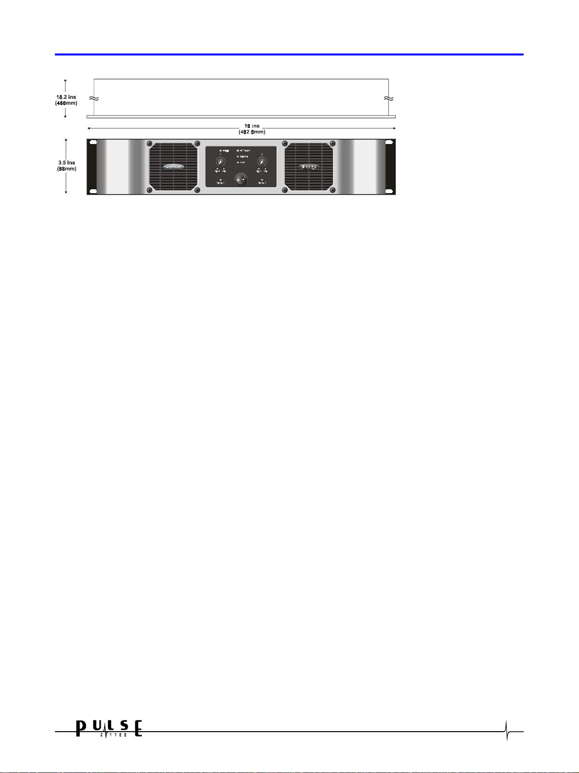
2.0 Mechanical Installation
A vertical rack space of 2U
(88mm high) is required,
with an in rack depth of
18.1 inches (460mm).
The amplifier protrudes
1.6 inches (40mm) from
the rack supports.
Mounting & unit dimensions
If the unit is likely to undergo extreme vibration through trucking and touring, front rack ear reinforcement
brackets and rear mounting plates must be fitted. These are available from your dealer. Damage caused by
insufficient support is not covered by the warranty .
T o prevent damage to the front panel finish, always use protective plastic cups or washers underneath the
rack mounting bolts.
Ventilation gaps between units are not required, however care must be taken to ensure that an unobstructed
free flow of clean air is possible from the back of the unit to the front. It is important that neither the rear
air intakes or front exhaust grilles are covered. The internal airflow of all PULSE amplifiers is designed to
minimize contamination of the electronics by the cooling air so fan filters will not normally be required. If
however, the amplifier is to be used in an environment where the intake air might be excessively dirty,
optional external fan filters should be purchased from your dealer . Fan filters should NOT be fitted unless
there is likely to be a problem as they require regular cleaning to stop them getting clogged. Clogged fan
filters will result in the amplifier going into premature temperature protect.
PLEASE NOTE: Users must ensure that glycol based smoke and related substances are not allowed to enter
the amplifier (fan filters will not help). Glycol based smoke is HIGHLY corrosive and prolonged exposure will
cause irreparable damage to your amplifier .
Do not expose the amplifier to rain or moisture during either operation or storage. If the unit does come
into contact with moisture, remove the AC power cord immediately and leave it in a suitably dry, warm place
to dry out.
Be aware that when any equipment is taken from a cold location into a hot humid one, condensation may
occur inside. Always allow time for the equipment to attain the same temperature as its environment before
applying the AC power cord.
5

3.0 AC Power Connection
WARNING! THIS APPLIANCE MUST BE GROUNDED.
The amplifier must always be connected to a 3-wire grounded AC outlet. The rack framework must also be
connected to the same grounding circuit. The unit must NOT be operated unless the power cables' ground
wire is properly terminated - this is important for personal safety as well as for proper control over the
system grounding.
The wires in the power lead are color coded as follows:
Green and Yellow......Ground
Blue......Neutral
Brown......Live/Hot
IMPORTANT: The PULSE 2x1100 is designed to use 50/60Hz AC power. Acceptable AC input supply voltage
ranges from 180V to 265V
The application of voltages above those specified may cause permanent damage that is not covered by your
warranty . Lower voltages may cause erratic operation.
Note that although the amplifier will operate correctly down to the voltages indicated, the quoted output
power will only be achieved with the stated nominal voltages.
IMPORTANT : The AC power fuse carrier on the rear of the unit must be fitted with the correct type and
rating of fuse, in this case T10A.
In the unlikely event of the AC fuse failing without good reason, disconnect the unit from the power supply,
and always replace with the appropriately rated fuse (as specified above) for continued protection against
damage and fire.
6
4.0 Audio Connections
Inputs
For each channel, there is a 1/4” phone jack socket, male & female XLR and pluggable removable terminal
block connectors provided for signal input on the rear panel of the amplifier . Each is electronically balanced
at an impedance greater than 10k ohms.
The removable terminal block, phone jack and both XLR connectors are internally wired in parallel, and
therefore any socket may be used for the input signal. The connectors not used in this manner function as
loop-through connectors for daisy chaining a number of channels.
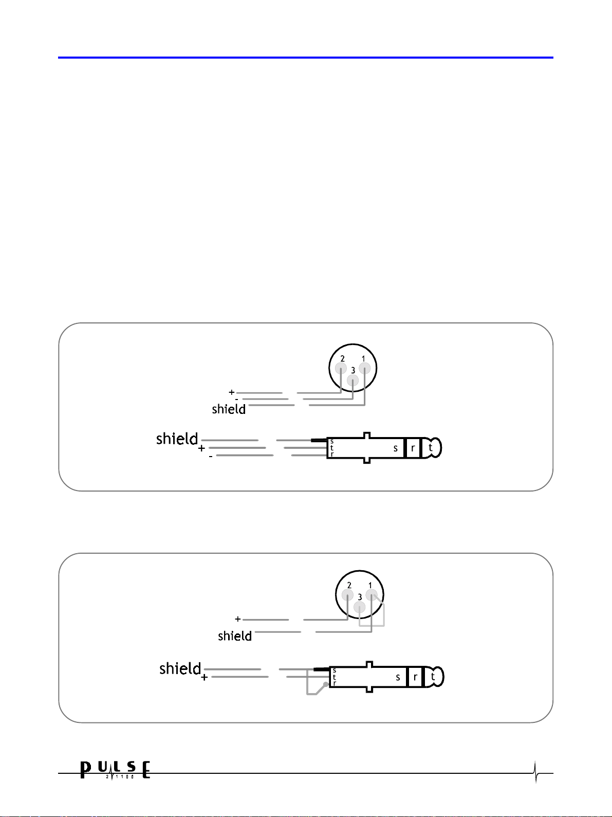
The ‘HOT, + or in phase’ connection for the removable terminal block is to pin 2 of the XLRs and the TIP of
the phone jack.
The ‘COLD, -, or out of phase’ connection for the removable terminal block is to pin 3 of the XLRs and the
phone jack RING.
The removable terminal block earth symbol pin, pin 1 of the XLR’ s and the phone jack SLEEVE are internally
connected to the chassis. The screen of the input cable should always be connected to one of these points to
ensure that EMC regulations are met. The cable shield ground should also be connected to the equipment
which is providing the input signal.
balanced wiring to pulse XLR
balanced wiring to pulse phone jack
When feeding the PULSE 2x1100 from unbalanced sources, connect the signal conductor to the + pin of the
removable terminal block, pin 2 of the XLR or the phone jack TIP, with the cable screen going to pins - and
ground of the removable terminal block, 1 and 3 of the XLRs or the SLEEVE and RING of the phone jack.
Unbalanced wiring to pulse XLR
Unbalanced wiring to pulse phone jack
For bridge mode operation, channel 1 is used as the input signal for the amplifier. The channel 2 input is
ignored when bridge mode is enabled.
7
 Loading...