

Crown Power-Tech-1 Owners Manual

Power-Tech .1 Series
Operation Manual
Obtaining Other Language Versions:
local Crown Distributor. If you need assistance locating your local distributor, please contact Crown at 574-294-8000.
This manual does not include all of the details of design, production, or variations of the equipment. Nor does it cover every possible
situation which may arise during installation, operation or maintenance.
The information provided in this manual was deemed accurate as of the publication date. However, updates to this information may have
occurred. To obtain the latest version of this manual, please visit the Crown website at www.crownaudio.com.
Trademark Notice:
Crown International. Other trademarks are the property of their respective owners.
Crown, Amcron and ODEP are registered trademarks of Crown International. Grounded Bridge is a trademark of
To obtain information in another language about the use of this product, please contact your
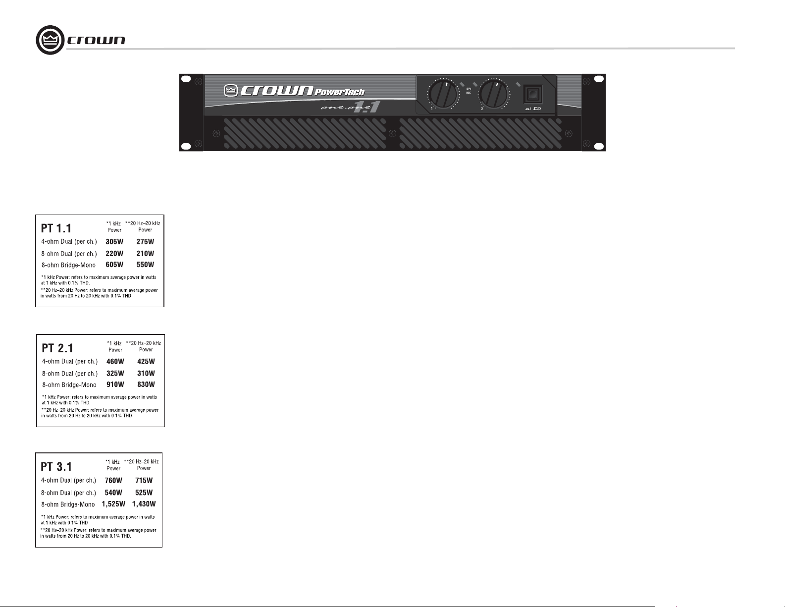
Power-Tech 1.1
Power-Tech 2.1
Power-Tech 3.1
Some models may be exported under the name Amcron.
©2002 by Crown Audio, Inc. P.O. Box 1000, Elkhart, Indiana 46515-1000 U.S.A. Telephone: 574-294-8000
®
132800-2
2/02
Important Safety
Instructions
1) Read these instructions.
2) Keep these instructions.
3) Heed all warnings.
4) Follow all instructions.
5) Do not use this apparatus near water.
6) Clean only with a dry cloth.
7) Do not block any ventilation openings. Install
in accordance with the manufacturer’s instructions.
8) Do not install near any heat sources such as
radiators, heat registers, stoves, or other
apparatus that produce heat.
9) Do not defeat the safety purpose of the polarized or grounding-type plug. A polarized plug
has two blades with one wider than the other.
A grounding-type plug has two blades and a
third grounding prong. The wide blade or the
third prong is provided for your safety. If the
provided plug does not fit into your outlet,
consult an electrician for replacement of the
obsolete outlet.
10) Protect the power cord from being walked on
or pinched, particularly at plugs, convenience
receptacles, and the point where they exit from
the apparatus.
11) Only use attachments/accessories specified
by the manufacturer.
12) Use only with a cart, stand, bracket, or table
specified by the manufacturer, or sold with the
apparatus. When a cart is used, use caution
when moving the cart/apparatus combination
to avoid injury from tip-over.
13) Unplug this apparatus during lightning storms
or when unused for long periods of time.
14) Refer all servicing to qualified service personnel. Servicing is required when the apparatus
has been damaged in any way, such as powersupply cord or plug is damaged, liquid has
been spilled or objects have fallen into the
apparatus, the apparatus has been exposed to
rain or moisture, does not operate normally,
or has been dropped.
15) To reduce the risk of fire or electric shock, do
not expose this apparatus to rain or moisture.
Power-Tech .1 Series Power Amplifiers
TO PREVENT ELECTRIC SHOCK DO NOT REMOVE
TOP OR BOTTOM COVERS. NO USER SERVICEABLE PARTS INSIDE. REFER SERVICING TO
QUALIFIED SERVICE PERSONNEL.
À PRÉVENIR LE CHOC ÉLECTRIQUE N’ENLEVEZ
PAS LES COUVERCLES. IL N’Y A PAS DES PARTIES SERVICEABLE À L’INTÉRIEUR. TOUS REPARATIONS DOIT ETRE FAIRE PAR PERSONNEL
QUALIFIÉ SEULMENT.
IMPORTANT
Power-Tech .1 Series amplifiers require Class 2
output wiring.
MAGNETIC FIELD
CAUTION! Do not locate sensitive high-gain equipment such as preamplifiers or tape decks directly
above or below the unit. Because this amplifier has
a high power density, it has a strong magnetic field
which can induce hum into unshielded devices that
are located nearby. The field is strongest just above
and below the unit.
If an equipment rack is used, we recommend locating the amplifier(s) in the bottom of the rack and the
preamplifier or other sensitive equipment at the top.
WATCH FOR THESE SYMBOLS:
The lightning bolt triangle is used to alert the user
to the risk of electric shock.
The exclamation point triangle is used to alert the
user to important operating or maintenance instructions.
page 2 Operation Manual

Power-Tech .1 Series Power Amplifiers
Table of Contents
Important Safety Instructions .............................................. 2
Table of Contents ................................................................. 3
1 Welcome ................................................................................... 4
1.1 Features.......................................................................... 4
2 How to Use This Manual ....................................................... 4
3 Setup.......................................................................................... 5
3.1 Unpack Your Amplifier ............................................... 5
3.2 Install Your Amplifier .................................................. 5
3.3 Ensure Proper Cooling ............................................... 5
3.4 Choose Input Wire and Connectors ......................... 6
3.5 Choose Output Wire and Connectors ...................... 7
3.6 Wire Your System ....................................................... 8
3.6.1 Stereo Mode...................................................... 8
3.6.2 Bridge-Mono Mode .......................................... 8
3.6.3 Parallel-Mono Mode......................................... 8
3.7 Set Input Sensitivity .................................................. 9
3.8 Connect to AC Mains .................................................. 9
3.9 Startup Procedure ....................................................... 9
4 Operation ................................................................................. 9
4.1 Precautions .................................................................. 9
4.2 Front Panel Controls and Indicators ......................... 10
4.3 Back Panel Controls and Connectors ............................. 11
5 Advanced Features and Options ......................................... 13
5.1 Protection Systems .................................................... 13
5.1.1. ODEP ................................................................. 13
5.1.2 Ultrasonic and Radio Frequency Protection.13
5.1.3 Drive Protection................................................ 13
5.1.4 Transformer Thermal Protection .................... 13
5.1.5 Fuses and Circuit Breakers.............................. 13
5.2 Option ........................................................................... 14
5.2.1 MT-BB................................................................. 14
6 Troubleshooting ...................................................................... 15
7 Specifications ......................................................................... 16
8 Service ..................................................................................... 17
8.1 Worldwide Service ...................................................... 18
8.2 US and Canada Service .............................................. 18
8.2.1 Service at a US or Canada Service Center ............. 18
8.2.2 Factory Service ..................................................... 18
8.2.3 Factory Service Shipping Instructions................... 18
9 Warranty .................................................................................. 19
Factory Service Information Form ........................................... 21
page 3Operation Manual
Power-Tech .1 Series Power Amplifiers
1 Welcome
Congratulations on purchasing a Crown
Power-Tech™.1 Series amplifier. Power-Tech .1
Series amplifiers are compact, professional
power amplifiers engineered to meet the most
demanding sound reinforcement needs. They
compare very favorably to more expensive
amplifiers, providing uncolored sound and signal-to-noise ratios commonly associated with
recording studios.
Modern power amplifiers are sophisticated
pieces of engineering capable of producing
extremely high power levels. They must be
treated with respect and correctly installed if
they are to provide the many years of reliable
service for which they were designed.
In addition, the Power-Tech .1 Series amplifiers
include a number of features which require
some explanation before they can be used to
their maximum advantage.
Please take the time to study this manual so
that you can obtain the best possible service
from your amplifier.
1.1 Features
• The patented ODEP
Grounded Bridge
vide performance and reliability that surpass all traditional designs.
circuitry and
design combine to pro-
• Safe with any load. Bridge-Mono and
Parallel-Mono modes make it easy to optimize the amplifier’s performance for a wide
range of loads.
• Complete protection against shorted outputs, mismatched loads, overheating,
input/output DC and high-frequency overload; full internal fault protection.
• Balanced phone jack inputs in parallel with
XLR input connectors. Barrier block input
connectors are optional.
• Backed by the industry’s ONLY three-year,
no-fault, fully transferable and extendable
warranty.
2 How to Use This
Manual
This manual provides you with the necessary
information to safely and correctly set up and
operate your amplifier. It does not cover every
aspect of installation, setup or operation that
might occur under every condition. For additional information, please consult Crown’s
Amplifier Application Guide (available online at
www.crownaudio.com), Crown Technical
Support, your system installer or retailer.
We strongly recommend you read all instructions, warnings and cautions contained in this
manual. Also, for your protection, please send
in your warranty registration card today. And
save your bill of sale—it’s your official proof of
purchase.
page 4 Operation Manual
Power-Tech .1 Series Power Amplifiers
3 Setup
3.1 Unpack Your Amplifier
Please unpack and inspect your amplifier for
any damage that may have occurred during
transit. If damage is found, notify the transportation company immediately. Only you can initiate a claim for shipping damage. Crown will
be happy to help. Save the shipping carton as
evidence of damage for the shipper’s inspection.
We also recommend that you save all packing
materials so you will have them if you ever
need to transport the unit. Never ship the
unit without the factory pack.
YOU WILL NEED (not supplied):
• Input wiring cables
• Output wiring cables
Rack for mounting amplifier (or a stable surface
for stacking)
WARNING: Before you start to set up
your amplifier, make sure you read and
observe the Important Safety Instructions found at the beginning of this manual.
3.2 Install Your Amplifier
CAUTION: Before you begin, make sure
your amplifier is disconnected from the
power source, with power switch in the
“off” position and all level controls
turned completely down (counterclockwise).
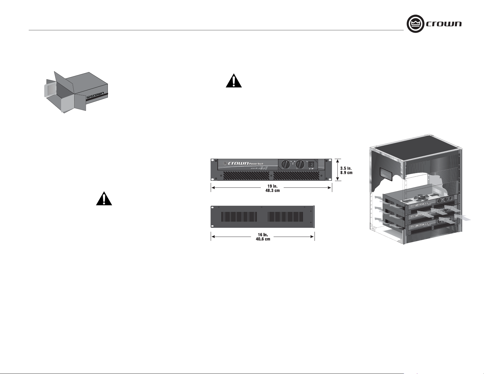
Use a standard 19-inch (48.3-cm) equipment
rack. See Figure 3.1 for amplifier dimensions.
You may also stack amps without using a cabinet.
NOTE: When transporting, amplifiers should be
supported at both front and back.
3.3 Ensure Proper Cooling
When using an equipment rack, mount units
directly on top of each other. Close any open
spaces in rack with blank panels. DO NOT
block front or rear air vents. The side walls of
the rack should be a minimum of 2 inches (5.1
cm) away from the amplifier sides, and the back
of the rack should be a minimum of 4 inches
(10.2 cm) from the amplifier back panel.
Figure 3.2 illustrates standard amplifier airflow.
Figure 3.1 Dimensions
Figure 3.2 Airflow
page 5Operation Manual
3 Setup
3.4 Choose Input Wire
and Connectors
Crown recommends using pre-built or professionally wired, balanced line (two-conductor
plus shield), 22-24 gauge cables and connectors. If you chose the MT-BB input barrier strip
option, use bare wire or spade lugs at the amplifier inputs. Otherwise use either 3-pin male XLR
connectors or TRS ¼-inch phone connectors.
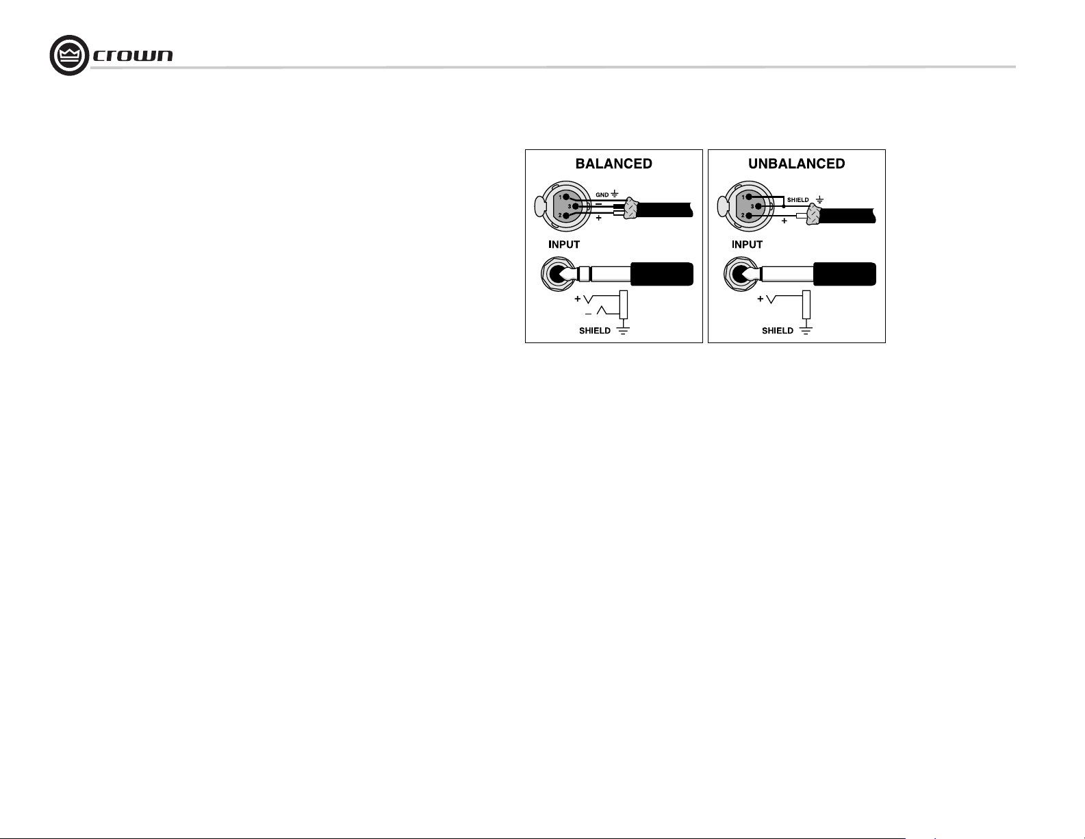
Figure 3.3 shows connector pin assignments for
balanced wiring, and Figure 3.4 shows connector pin assignments for unbalanced wiring.
NOTE: Custom wiring should only be performed by qualified personnel.
Figure 3.3 Balanced Input
Connector Wiring
Power-Tech .1 Series Power Amplifiers
Figure 3.4 Unbalanced Input
Connector Wiring
page 6 Operation Manual
Power-Tech .1 Series Power Amplifiers
3 Setup
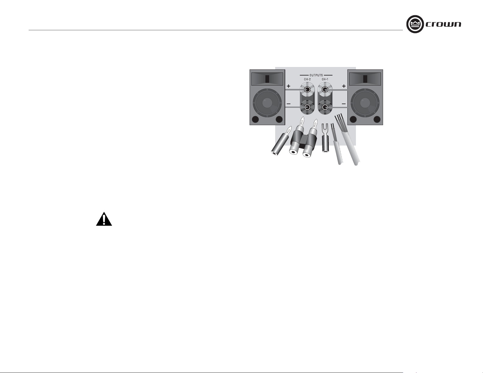
3.5 Choose Output Wire and Connectors
Crown recommends using pre-built or professionally wired, high-quality, two-conductor,
heavy gauge speaker wire. Use bare wire, a dual
banana plug or spade lugs on the amplifier end
of each speaker cable (Figure 3.5). To prevent
the possibility of short-circuits, wrap or otherwise insulate exposed loudspeaker cable connectors.
Using the guidelines below, select the appropriate size of wire based on the distance from
amplifier to speaker.
up to 25 ft. 16 gauge
101-150 ft. 8 gauge
151-250 ft. 6 gauge
Distance Wire Size
26-40 ft. 14 gauge
41-60 ft. 12 gauge
61-100 ft. 10 gauge
Figure 3.5 Output Connector Wiring
CAUTION: Never use shielded cable for
output wiring.
page 7Operation Manual
3 Setup
Power-Tech .1 Series Power Amplifiers
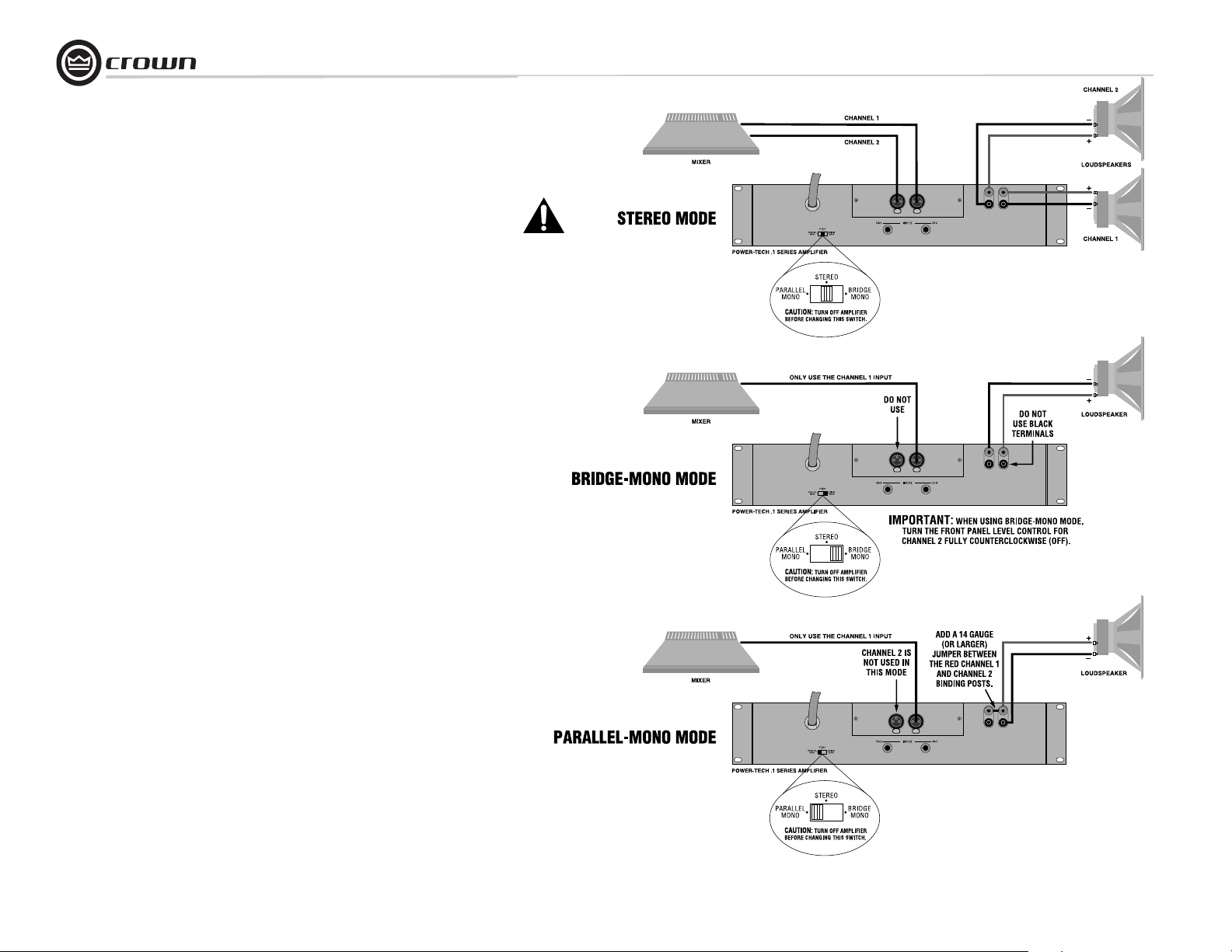
3.6 Wire Your System
Turn down the Level controls (fully counterclockwise) and turn off the amplifier before wiring it as described below. Refer to Figure 3.6.
3.6.1 St ereo Mode
Set the back panel stereo/mono switch to Stereo.
INPUTS: Connect input wiring to both channels.
OUTPUTS: Maintain proper polarity (+/–) on
output connectors.
Connect Channel 1 positive (+) speaker load to
Channel 1 positive terminal of amp; repeat for
negative (–). Repeat Channel 2 wiring as for
Channel 1.
3.6.2 Bridge-Mono Mode
Set the back panel stereo/mono switch to
Bridge-Mono.
INPUTS: Connect input wiring to Channel 1
only.
OUTPUTS: Connect the speaker across the positive terminals of each channel. Do not use the
negative terminals when the amp is being operated in Bridge-Mono mode.
NOTE: The Channel 2 level control should
be set fully counter-clockwise when operating the amplifier in Bridge-Mono mode.
3.6.3 Parallel-Mono Mode
CAUTION: Parallel-Mono wiring requires
installation of a jumper wire. Do not
switch to Stereo or Bridge-Mono mode
until this output jumper wire is removed.
IMPORTANT: The Channel 2 IOC indicator
will remain lit when operating in Parallel-Mono mode.
Set the back panel stereo/mono switch to
Parallel-Mono.
INPUTS: Connect input wiring to Channel 1
only.
OUTPUTS: Add a 14 AWG gauge (or larger)
jumper between the red(+) Channel 1 and Channel 2 binding posts. Connect the speaker positive (+) lead to the Channel 1 red (+) terminal.
Connect the speaker negative (–) lead to the
Channel 1 black (–) terminal.
NOTE: Use only the Channel 1 level control.
NOTE: Crown provides a reference of wiring pin
assignments for commonly used connector
types in the Crown Amplifier Application Guide,
available online at www.crownaudio.com.
Figure 3.6 Three System Connection Methods
page 8 Operation Manual
 Loading...