

Crown PIP-USP4 User Manual
Networked PIP Series Reference Manual
PIP - LITE
PIP - USP4-CN
Network Programmable Input Processors with HiQnet™, TCP/IQ™,
SmartAmp™Features, Load Supervision for Crown PIP2™-Compatible
Amplifi ers, and CobraNet™ Connectivity (USP4-CN only)
Obtaining Other Language Versions : To obtain information in another language about
the use of this product, please contact your local Crown Distributor. If you need assistance
locating your local distributor, please contact Crown at 574-294-8000.
This manual does not include all of the details of design, production, or variations of the
equipment. Nor does it cover ever y possible situation which may arise during installation,
operation or maintenance. If special assistance is needed beyond the scope of this manual, or
the software online help, please contact the Crown Technical Support Group.
The information provided in this manual was deemed accurate as of the publication date.
However, updates to this information may have occurred. To obtain the latest version of this
manual, please visit the Crown website at w ww.crownaudio.com.
Tra de mark Notice : Crown, Crown Audio, Amcron, Com-Tech, Macro-Tech, IQ and IQ
System are registered trademarks of Crown International. TCP/IQ, SmartAmp, IQ2, PIP and
PIP2 are trademarks of Crown International. HiQnet is a trademark of Harman International
Industries, Inc. Other trademarks are the property of their respective owners.
Some models may be exported under the name Amcron®.
©2009 by Crown Audio® Inc., 1718 W. Mishawaka Rd., Elkhart, Indiana 46517-9439 U.S.A.
Telephone: 574-294-8000
1367 63-7 9/0 9
Networked PIP Series
Crown Technical Support
1718 W. Mishawaka Rd., Elkhart, Indiana 46517-9439 U.S.A.
Phone: 800-342-6939 (North America, Puerto Rico and Virgin Islands) or 574-294-8200
Fax: 574-294-8 301 Internet: http://www.crownaudio.com
WATCH FOR THESE SYMBOLS. The exclamation point triangle
is used to alert the user to important operating or maintenance
instructions.
The lightning bolt triangle is used to aler t the user to the risk of
electric shock.
This product complies with CISPR22 Emissions standard,
EN55103-1 Emissions standard, and EN55103-2 Immunity standard.
WARNING
TO REDUCE THE RISK OF ELECTRIC
SHOCK, DO NOT EXPOSE THIS
EQUIPMENT TO RAIN OR MOISTURE!
FCC COMPLIANCE NOTICE
This device complies with part 15 of the FCC rules. Operation is subject to the
following two conditions: (1) This device may not cause harmful interference, and
(2) this device must accept any interference received, including interference that may
cause undesired operation.
page 2
CAUTION: Changes or modifi cations not expressly approved by the part y
responsible for complicance could void the user’s authority to operate the euqipment.
NOTE: This equipment has been tested and found to comply with the limits for
a Class B digital device, pursuant to part 15 of the FCC Rules. These limits are
designed to provide reasonable protection against harmful interference in a
residential installation. This equipment generates, uses, and can radiate radio
frequency energy and, if not installed and used in accordance with the instruction
manual, may cause harmful interference to radio communications. However, there
is no guarantee that interference will not occur in a particular installation. If this
equipment does cause harmful interference to radio or television reception, which
can be determined by turning the equipment off and on, the user is encouraged to try
to correct the interference by one or more of the following measures:
• Reorient or relocate the receiving antenna.
• Increase the separation between the equipment and receiver.
• Connect the equipment into an outlet on a circuit different from that
to which the receiver is connected.
• Consult the dealer or an experienced radio/ TV technician for help.
Reference Manual

Networked PIP Series
DECLARATION of CONFORMITY
Harman International
1718 W. Mishawaka Rd.
Elkhart, IN 46517 U.S.A.
European Representative’s Name and Address :
David Budge
10 Harvest Close
Yateley GU46 6YS
United Kingdom
Equipment Type: Control System Components
Family Name: PIP
Model Name: PIP-Lite, PIP-USP4-CN
EMC Standards:
EN 55103-1:1997 Electromagnetic Compatibility – Product Family Standard for Audio, Video,
Audio-Visual and Entertainment Lighting Control Apparatus for Professional Use, Part 1:Emissions
EN 55103-1:1997 Magnetic Field Emissions-Annex A @ 10 cm and 1 M
EN 61000-3-3:1998 Limitation of Voltage Fluctuations and Flicker in Low-Voltage Supply
Systems Rated Current ≤ 16A
EN 55022:2006 Limits and Methods of Measurement of Radio Disturbance Characteristics of ITE:
Radiated, Class B Limits; Conducted, Class B
EN 55103-2:1997 Electromagnetic Compatibility – Product Family Standard for Audio, Video,
Audio-Visual and Entertainment Lighting Control Apparatus for Professional Use, Part 2: Immunity
EN 61000-4-2:2001 Electrostatic Discharge Immunity (Environment E2-Criteria B, 4k V Contact,
8k V Air Discharge)
EN 61000-4-3:2006 Radiated, Radio-Frequency, Electromagnetic Immunit y (Environment E2,
criteria A)
EN 61000-4-4:2007 Electrical Fast Transient /Burst Immunity (Criteria B)
EN 61000-4-5:2006 Surge Immunity (Criteria B)
EN 61000-4-6:1996 Immunit y to Conducted Disturbances Induced by Radio-Frequency Fields
(Criteria A)
EN 61000-4-11:2004 Voltage Dips, Short Interruptions and Voltage Variation
FOR COMPLIANCE QUESTIONS ONLY:
Susan Whitfi eld
574-294-8289
sue.whitfi eld @harman.com
Safety Standard:
IEC 60065: 2001 + AMP1: 2005 Safety Requirements – Audio V ideo and Similar Electronic Appar atus
I certify that the product identifi ed above conforms to the requirements of the EMC Council Directive 89/335/
EEC as amended by 92/31/EEC, and the Low Voltage Directive 73 /23/EES as amended by 93/68/EEC.
Signed
Andrew Stump
Title: Director of Manufacturing
Reference Manual
Date of Issue : December 1, 2009
page 3

Networked PIP Series
Quick Install Procedure
This procedure is provided for those who would like to install the PIP card in the shortest time
possible and are already familiar with Harman Pro System Architect and HiQnet. A more complete
installation procedure is outlined in the installation section.
Prepare the amplifi er :
1. Turn down the level controls of the amplifi er and turn off the amplifi er.
2. Unplug the power cord from the AC mains.
3. Remove the existing PIP or cover from the amplifi er back panel (two screws).
4. On the PIP-USP4-CN, make sure that the input sensitivit y switches located inside the
amplifi er are in the 26dB mode (middle) position for both, channel 1 and 2.
Install the PIP module into the amplifi er:
5. Carefully ground yourself to the chassis of the amplifi er before installing the PIP card. It is a
good idea to maintain ground contact between yourself and the amplifi er while inserting the
module into the amplifi er in the nex t step.
6. Position the PIP module so the ribbon cable connectors located along the back edge on the
underside of the module can be clearly seen. Attach the ribbon cables from the amplifi er to
the ribbon-cable connectors. For PIP-Lite, the 20 pin cable (A) should go to the connector
closest to the corner (J2A) and the 18 pin cable (B) should go to the other connector. For
PIP-USP4-CN, make sure to install the supplied ferrite core to the 18 pin cable (B) before
connecting. The 20 pin cable (A) should go to the connector further inside and away from the
corner (AJ9), and the 18 pin cable should connect to the one closest to the corner (B J5) .
Important: Be careful when at taching the ribbon cable to the connector. Applying pressure
to an improperly seated connector could cause the keying tabs, which ensure proper pin
alignment, to break. Connecting the ribbon cables with improper pin alignment will likely
result in damage to the PIP.
page 4
7. With both cables fi rmly attached, turn the PIP back to an upright position. Verif y that the
cables run untwisted between the amplifi er and the PIP. Insert the PIP into the amplifi er while
taking care not to crimp, pinch or stretch the ribbon cables.
8. Tighten the two PIP mounting screws until it is secured to the amplifi er back panel, making
sure the supplied star-washers contact the PIP panel for a good ground connection.
9. Make sure the amplifi er is left in Dual mode – Bridging is done via software (USP4-CN only)
Install the wiring:
10. Connect the PIP to the Ethernet network used for control. Each PIP must connect to its own
port on a 100 Megabit Ethernet Switch with a standard straight CAT5 network cable. A 10
Megabit connection will work with the PIP-Lite but is not recommended for systems with a
high number of components. A 10 Megabit connection will not work with the PIP-USP4-CN.
11. Connect the amplifi er back to the AC mains and reset the back panel input attenuators to
the proper levels. For the USP4-CN the input attenuators should be set to wide open, no
attentuation for all the features to function properly.
Reference Manual
Networked PIP Series
Controls, Indicators and Connectors
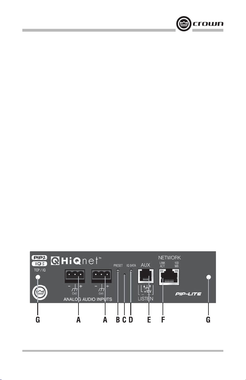
PIP-Lite
A. Balanced Audio Input Connectors
3-pin removable barrier-strip connectors, one per channel.
B. Preset Indicator
Signals the number of the current preset, if active, by fl ashing a series of fl ashes equal
to the current preset number.
C. Reset/Preset Switch
Used to change presets, restore set tings to factory default or restore all the presets to
the factory defaults. During operations of the switch, the Data indicator fl ashes as an
aid to the user.
D. Data Indicator
Flashes when the PIP-Lite receives a valid command that is addressed to the PIP-Lite.
E. AUX Connector
AUX input, AUX output, and Listen Bus/Foldback.
F. N e t work C o nnector
The network connector is a standard RJ-45 connector that allows the PIP-Lite to
connect to an Ethernet network. Connection is made using a standard Category 5
or better cable to a network switch port. For compliance with emission regulations,
the supplied ferrite core must be placed on the CAT5 cable, with the cable making
two passes through the core as shown in the fi gure below. The Link Activity LED
indicates data activity on the network line. The 100 MB LED indicates that the data
is at 100 Megabits.
G. Mounting Holes
Reference Manual
PIP-Lite Controls, Indicators and Connectors
(Note: Actual Produ ct Artwork May Vary Slightly)
page 5
 Loading...