

Page 1
P.I.P.-RPA
P.I.P.-RPAT
© 2002 by Crown Audio, Inc., P.O. Box 1000, Elkhart, IN 46515-1000 U.S.A.
Telephone: 574-294-8000. Fax: 574-294-8329. Trademark Notice: PIP is a
trademark and Crown and P.I.P. are registered trademarks of Crown
International. Other trademarks are the property of their respective owners.
125658-4
Printed on
recycled paper.
7/02
Page 2

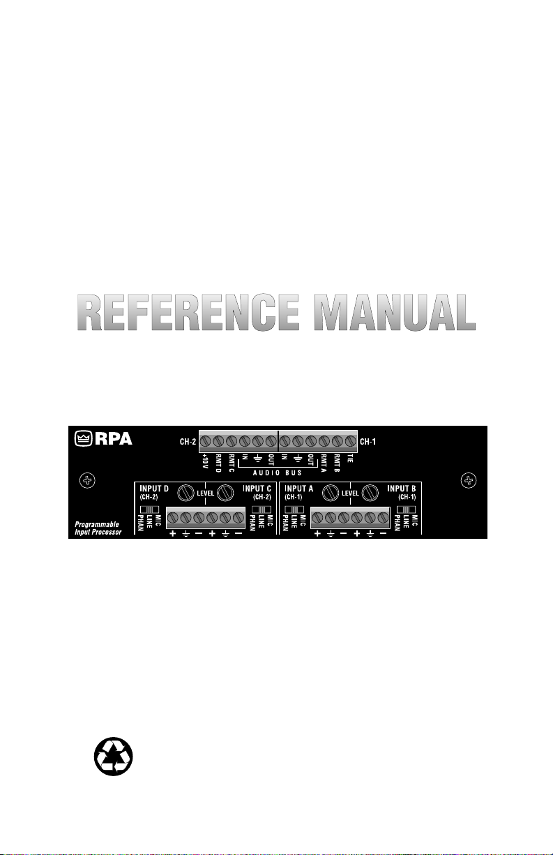
Fig. 1.1 P.I.P.-RPA
P.I.P.-RPA
Page 2
Reference Manual
Page 3

P.I.P.-RPA
1 Welcome
Thank you for purchasing the Crown
®
P.I.P.
-RPA accessory.
ules are designed to install quickly
into the rear panel of many Crown
amplifiers. PIP stands for “Programmable Input Processor.” Their versatile features expand the capabilities of
your amplifier and enable you to customize it for your particular needs.
The P.I.P.-RPA adds the features of a
remote-controlled 4-input 2-output
mixer to the input of your amplifier.
Each of the four main audio inputs is
balanced and can accept signal levels ranging from low-level microphones to line-level devices. Phantom power is available for microphones. The P.I.P.-RPAT also has1:1
isolation transformers for each input.
Unbalanced “Audio Bus” inputs and
outputs, similar to “Aux Send” and
“Aux Return” on a typical mixer, are
provided. The Audio Bus inputs allow an almost unlimited number of
sources to be connected at each
amplifier input. The Audio Bus outputs allow the mixed signal of Channel 1 and 2 to be fed to other amplifiers or components.
Mixing the input signals of the P.I.P.RPA is accomplished remotely using
a two-wire remote control to control
the VCA (voltage-controlled amplifier) of each input. The remote control
can be a fixed resistor for a fixed
attenuation or a 10 K potentiometer
(pot) for variable attenuation. A 10
PIP
™
mod-
VDC source is conveniently provided
on the PIP for the remote. If no attenuation is desired, the 10 V source must
be connected directly to the remote
control input. Up to 84 dB of attenuation is available with each VCA. If
desired, more than one input can be
controlled by the same remote control.
A “voice-over” feature is provided so
Inputs A and C can have priority over
Inputs B and D. When activated, the
voice-over circuitry causes the lowpriority inputs to “duck” by a preset
attenuated level. The input priority
(and signal routing) is programmed
with an 8-segment DIP switch on the
top circuit board of the PIP
ion “Tie” feature, controlled remotely,
enables you to tie one channel to the
other. Using it, the audio from one or
more inputs can be directed to both
outputs and their priorities linked.
.
A compan-
Feature Summary
❏ Remote-controlled mixing of 4
balanced mic/line inputs with up to
84 dB of attenuation.
❏ Adjustable input sensitivity.
❏ Phantom power available for mics.
❏ Audio Bus inputs and outputs.
❏ 10 V provided for remote-controls.
❏ Voice-over capability with adjust-
able sensitivity and duck level.
❏ Ch. 1 and 2 can be tied together.
❏ 1:1 isolation transformers (P.I.P.-
RPAT).
Reference Manual
Page 3
Page 4
P.I.P.-RPA
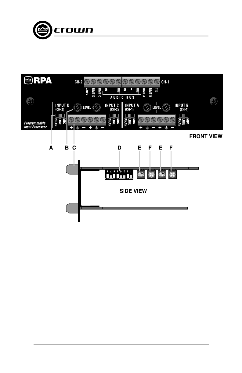
Fig. 2.1 Facilities
2 Facilities
A. Input Mode Switches
These gold-plated three-position
switches select the mode of each
main audio input: mic-level, line-level,
or mic-level with phantom power.
B. Input Level Controls
The level of each main audio input
can be adjusted with these level controls. They have a range of 36 dB.
Page 4
Using them, you can compensate for
a wide range of input signal levels.
C. Barrier Connectors
All connections are made using these
screw-down barrier-block connectors.
Important:
unless the wire ends are first tinned.
Strip no more than
of insulation from the wire ends.
Do not use stranded wire
1
/4 inch (6.4 mm)
Reference Manual
Page 5

P.I.P.-RPA
Main Audio Inputs
There are four balanced main audio
inputs. Inputs A and B are normally
fed to Ch. 1 of the amplifier. Inputs C
and D are normally fed to Ch. 2. Each
input remains off (attenuated 84 dB)
until a positive DC voltage greater
than 5 V is applied to the corresponding remote input (10 V results
in no attenuation).
Remote Inputs / 10 V Output
There is a remote control input for
each main audio input and a 10 VDC
supply output for feeding them (see
Section 3.6). Each main audio input is
normally off (attenuated 84 dB) until a
positive DC voltage greater than 5 V is
connected to the corresponding remote input. If the 10 V supply is
strapped directly to a remote input,
the main audio input will have no
attenuation.
Audio Bus Input / Output
There is also an unbalanced audio
bus input and output for each channel. Each bus input and output pair
shares a common ground connection. The bus outputs contain the
mixed audio signals from Inputs A–D
which feed the corresponding amplifier channel.
Note: The audio bus outputs are
inverted. The mating bus inputs correct this by again inverting the signal.
Tie Input
Finally there is a “Tie” input which is
a logic input and can be switched on
by feeding a positive DC voltage to it.
It enables the audio inputs and voiceover priorities of Ch. 1 to be “tied” to
Ch. 2 and vice versa.
D. Routing/Priority Switch
This 8-segment DIP (dual in-line
package) switch is comprised of eight
individual switches. Flipping them
down toward the bottom circuit board
turns them off. Flipping them up toward the top circuit board turns them
on. The DIP switch is used to program the routing and priority of each
main audio input. See Section 3.1.
E. Duck Level Controls
The “duck level” is the amount of
attenuation applied to a lower priority
input when a higher priority input is
activated. The first control (closest to
the front panel of the PIP) sets the
duck level triggered by Input A and
the third control sets the duck level
triggered by Input C. The attenuation
range is 0 to 70 dB.
F. Voice-Over Sensitivity
Controls
The “voice-over sensitivity” is the level
required from an input signal before
the “duck” circuit is activated, causing lower-priority inputs to duck to a
preset attenuation level. The second
control (closest to the front panel)
sets the sensitivity of Input A and the
fourth control sets the sensitivity of
Input C. The voice-over sensitivity
controls have a range of 26 dB.
Reference Manual
Page 5
Page 6
P.I.P.-RPA
3 Installation
This section provides general installation instructions. For additional information on using Crown PIP modules, visit the Crown website at
www.crownaudio.com.
The internal controls of the P.I.P.RPA must be set prior to installation.
Note: An accessory, a PIP extender
card (P.I.P.-EXT), is available if you
prefer to make the voice-over and
duck level adjustments while the PIP
is operating. This allows you to test
your settings and easily make
changes while you fine-tune the installation.
Fig. 3.1 P.I.P.-EXT Accessory
3.1 Setting the
InputRouting/Priority
Switch
The routing/priority switch serves two
purposes. First, it works together with
the Tie function to control audio signal routing. Second, it sets the priority of Inputs B, C and D (Input A
always has the highest priority. Input
C always has the second highest
priority.)
The routing/priority switch is the 8segment DIP switch shown in Figures 2.1 and 3.2. Notice that it is
mounted upside-down to the underside (component side) of the top
circuit board.
Normally the mix of Inputs A and B feeds
Channel 1 of the amplifier and the mix of
Inputs C and D feeds Channel 2. This
can be changed by the routing/priority
switch when the Tie function is turned on
(see Section 3.7).
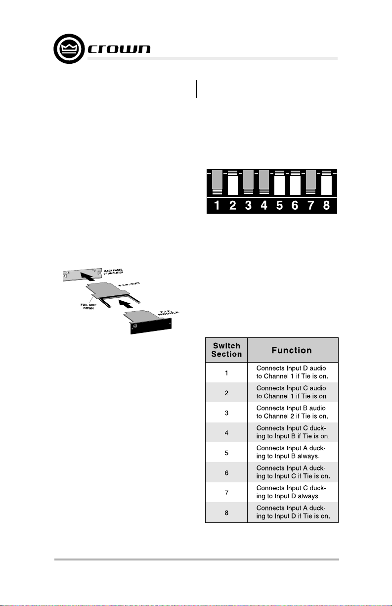
Fig. 3.2 Priority/Routing DIP Switch
(Inverted for Readability)
When the Tie function is on, the audio
from Input A is automatically fed to
both Channels 1 and 2. The audio
from the remaining inputs can also
be tied to both channels using the
routing/priority switch. The first three
switch sections control the routing of
Inputs B–D as shown in Figure 3.3.
Fig. 3.3 Routing/Priority DIP
Switch Functions
Page 6
Reference Manual
Page 7
P.I.P.-RPA
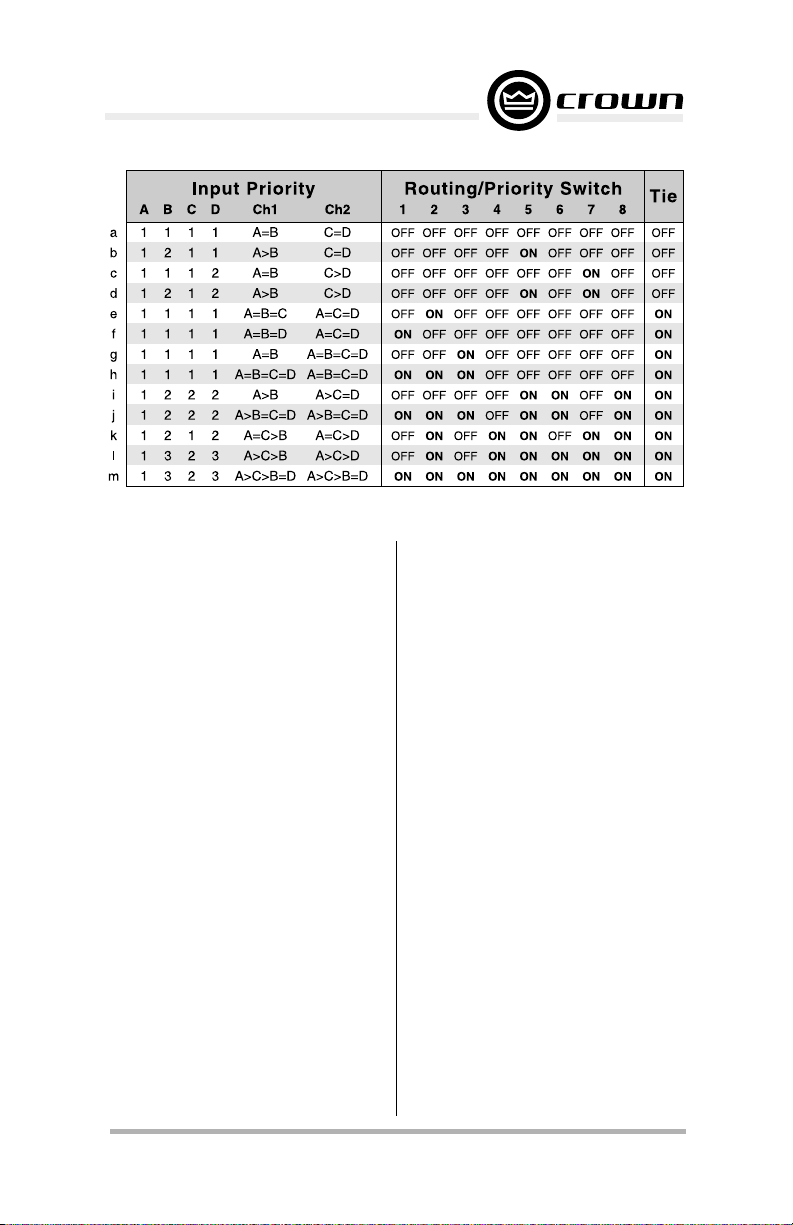
Fig. 3.4 Sample Routing/Priority DIP Switch Settings
The priority of each input determines
whether it will override or “duck” under another input. For example, you
can feed background music into Input B and a paging mic into Input A.
By setting the priority of Input B lower
than Input A, the background music
will be automatically attenuated when
someone uses the paging mic.
The table in Figure 3.4 shows some
common settings for the switch and
what they mean—it does not show
every possible combination. The
highest priority is 1 and the lowest
priority is 3. Notice that Input A is
always set to priority 1. Input C is
usually set to priority 1 unless the
channels are tied together. The reason for this is because only Inputs A
and C have voice-over sensing circuitry. Since the other inputs do not
have this sensing capability they must
have a lower priority.
As mentioned earlier, the routing/
priority switch works in conjuction
with the Tie function. The table in
Figure 3.3 shows that all the DIP
switch sections except 5 and 7 function only when the Tie function is on.
The Tie function is designed to be
remotely controlled and is fully described in Section 3.7. If you have no
desire to control it remotely and want
to leave it on, simply install a jumper
between the 10-V output and the Tie
input on the front panel of the PIP
3.2 Setting the Duck Level
If you gave all four main audio inputs
the same priority you can skip to
Section 3.4. When two or more inputs
have a different priority, the duck
level is the attenuation level the lowpriority inputs will duck when the
voice-over circuitry is activated.
The duck circuits have an attack time
of 15 milliseconds and a decay time
of 1.5 seconds. This means the duck
circuit needs only 15 milliseconds to
attenuate the low-priority input(s)
when the voice-over circuit triggers
it. However, when the voice-over circuit is no longer activated, the duck
circuit waits about 1.5 seconds be-
Reference Manual
Page 7
Page 8

P.I.P.-RPA
fore it removes the attenuation. The
result is a fast transition when the
duck circuit is activated and a slower,
smooth transition when it is deactivated.
The duck level controls have a wide
0–70 dB range as shown in Figure
3.6. (The setting numbers in the table
in Figure 3.6 refer to the tick marks on
the duck level pot in Figure 3.5.)
Fig. 3.5 Duck/Voice-Over Control
(Inverted for Readability)
Note:Note:
Note: Since Inputs A and C have
Note:Note:
independent ducking circuitry, they
Fig. 3.6 Duck Level Settings
may be used to provide two different
ducking levels for lower priority inputs. For example, assume the routing/priority switch has been set to the
“l” setting (as shown in Figure 3.4)
and the Tie function has been turned
on. This setting makes Input A priority
1, Input C priority 2, and Inputs B and
D priority 3. If the ducking level for A
is 70 dB, and the ducking level for C
is 46, Inputs B, C and D will all duck 70
dB when there is a signal over the
sensitivity threshold on A. Inputs B
and D will duck 46 dB when a signal
on Input C surpasses its threshold. In
this scenario, background music on B
and D would be pulled under by a
normal page on Input C, and Input A
could be reserved for emergency announcements.
3.3 Setting the Voice-Over
Sensitivity
If you gave all four main audio inputs
the same priority, skip to Section 3.4.
When two or more inputs have a
different priority, the voice-over sensitivity circuits set the points at which
Input A and C will activate their respective ducking circuits.
Only Inputs A and C have signalsensing capability so they will always have the highest priorities.
Each voice-over sensitivity circuit
senses the input signal level after the
input level control (the pot accessed
through the front panel of the PIP)
and before the remote-controlled attenuator. This is shown in the block
diagram in Figure 3.19. This means
that the remote attenuation setting
does
not affect the duck level.
Figures 2.1 and 3.5 show voice-over
sensitivity controls. They look identi-
Page 8
Reference Manual
Page 9

P.I.P.-RPA
cal to the duck level controls. Figure
3.7 shows how the control can increase the relative sensitivity.
When the control is set to position 1
(0 dB) it is so insensitive the voiceover circuit will almost never trigger.
When it is set to position 12, the
sensitivity is increased 26 dB.
Fig. 3.7 Voice-Over
Sensitivity Settings
Setting the voice-over sensitivity is
simply a matter of gradually turning
up the sensitivity control until it is set
too high, then backing it down a little
to an optimum setting. This will require you to install and remove the
P.I.P.-RPA several times while the
sensitivity setting is refined. If you
prefer not to repeatedly install and
remove the PIP from the amplifier
you can purchase our P.I.P.-EXT accessory, an extender card which will
allow you to connect the PIP outside
the amplifier so you can make adjustments to it during system operation.
The exact procedure for setting the
voice-over sensitivity will vary de-
pending upon your particular application. The steps we provide are for
a common scenario which shows the
principles involved. If you need more
information please contact our Technical Support Group at 800/342-6939,
or contact your local representative.
For the sake of simplicity our example will describe how to set just
one of the two voice-over sensitivity
controls. We will also assume that
you do not have a P.I.P.-EXT. The
procedure involves turning up the
voice-over sensitivity until it is triggered by the ambient noise level
then backing off a little so that only an
audio signal triggers it.
Procedure
Example: Input B will be fed a line-
level background music signal and
will be assigned a priority of 2 by the
routing/priority switch. Input A will be
fed a mic-level signal from a paging
mic which requires phantom power.
The paging mic will automatically override the background music whenever
it is used. The routing/priority switch
will be set to setting “b” to accomplish
this (refer to Figure 3.4).
1. Set the input mode switch (Figure
3.8) to the appropriate setting for
each input. Input A should be set to
“PHAN” for the phantom powered
microphone and Input B should be
set to “LINE” for the line-level feed.
2. Set the input level controls of
Inputs A and B for the required
system gain (Figure 3.8).
3. Refer to Section 3.5 and connect
the audio cables to the
appropriate inputs (A and B).
Audio signals will be needed next
to adjust the voice-over circuit of
Reference Manual
Page 9
Page 10

Fig. 3.8 Steps 1 & 2
Input A.
4. If you haven’t yet done so, adjust
the duck level per Section 3.2.
5. Turn the voice-over sensitivity
control of Input A to its middle
setting
(setting 6 in Figure 3.5).
6. Turn off the power amplifier and
unplug its power cord. Refer to
Section 3.4 and install the PIP
into the amplifier. Reconnect
power to the amplifier and turn it
on.
7. With the ambient noise level of
Input A at a maximum, check to
see if Input B has ducked.
8. Turn off the power amplifier,
unplug its power cord and remove
the PIP again.
9. Adjust the voice-over sensitivity control in the following manner: If Input B has NOT yet ducked
increase the voice-over sensitivity
control one mark. If it HAS ducked,
decrease the voice-over sensitivity control one mark.
10.Repeat steps 6 through 9 until the
setting has been found where the
voice-over sensitivity control just
begins to allow Input B to duck.
Back off the sensitivity control
1
/4 turn from this point. The voice
over circuit should now trigger on
a legitimate signal and not noise.
Notice in Figure 3.7 that turning the
P.I.P.-RPA
voice-over sensitivity control fully
counterclockwise (setting 0) will turn
the circuit off.
The voice-over sensitivity control has
26 dB of adjustable range. Since the
voice-over circuitry follows the input
mode switch and input level control,
the actual sensitivity level can vary
widely. To increase the relative sensitivity of the voice-over circuit, turn
up the input level control and turn
down the amplifier level or the remote controlled attenuator. Remember, the remote controlled attenuator
is located after the voice-over circuit
so it can be used to reduce the gain
added with the input level control. If
less relative voice-over sensitivity is
desired, do just the opposite: Turn
down the input level control and turn
up the amplifier level control or the
remote-controlled attenuator. (Refer
to Figure 3.7.)
3.4 Installation
Procedures
CAUTION: Before connecting this or
any PIP to your amplifier, it is important to turn its level controls
down, turn it off and
remove the AC powerremove the AC power
remove the AC power.
remove the AC powerremove the AC power
Don’t touch the circuitry while the
amp is plugged in. Even though the
amplifier is off, there could still be
enough energy remaining to cause
electric shock.
You may need a phillips screwdriver
to remove the existing PIP module or
panel from your amplifier.
1. Turn down the level controls (full
counterclockwise), turn off the
amplifier and unplug it from the AC
power source.
Page 10
Reference Manual
Page 11

P.I.P.-RPA
L
E
N
A
P
K
C
A
B
R
E
I
F
I
L
P
M
A
F
O
.
P
.
I
.
P
U
D
O
M
Fig. 3.9 Installation into a
Standard PIP Amplifier
FROM AMPLIFIER
P
I
P
A
R
E
T
P
A
D
A
2
B
A
18 PIN (B)
B
20 PIN (A)
Fig.3.10 PIP2 Input Adapter
Connection
L
E
N
A
P
K
C
A
B
2
IP
P
F
O
R
IE
IF
L
P
M
A
R
E
T
P
A
D
A
2
IP
P
.
.I.P
P
U
D
O
M
Fig. 3.11 Installation into a
PIP2 Amplifier
2. Remove the existing PIP module
or panel (two screws). For
PIP2
amplifiers, this may involve
disconnecting the PIP from a PIP2
input adapter (see Figures 3.10
and 3.11). If a PIP2 input adapter is
already present, do not remove
the ribbon cables from the
adapter. Otherwise you will have
to reconnect them in the next step.
3.
Standard PIP Amplifiers
: Align the
edges of the P.I.P.–RPA in the PIP
card rails and firmly push the unit
E
L
in until it is seated against the
mounting bracket (see Figure 3.9).
PIP2 Amplifiers:
(Requires a PIP2
input adaptor. Crown part number
Q43528-1.) Connect the PIP2 input
adapter to the two input cables of
the amplifier (see Figure 3.10).
Notice that the PIP2 input adapter
should be positioned with the PIP
edge connector on top and facing
away from the amplifier. The 20pin cable (A) is connected first
then the 18-pin cable (B) is
connected. Both ribbon cables
should extend below the PIP2
input adapter.
Next, insert the edge connector of
the P.I.P.–RPA into the PIP2 input
adapter (see Figure 3.11) and
insert the assembly into the PIP
opening in the back of the
amplifier.
E
L
4. Secure the P.I.P.–RPA with the two
screws and lock washers
provided. (The lock washers are
important because they bond the
PIP to the chassis ground of the
amplifier.)
5. Connect input and output wiring.
6. Plug in the amplifier and turn it on.
Adjust its level controls to a
desired setting.
Do not tamper with the circuitry. Circuit changes made by unauthorized
personnel, or unauthorized circuit
modifications are not allowed.
Remember: Crown is not liable for
any damage resulting from overdriving other components in your sound
system.
Reference Manual
Page 11
Page 12

P.I.P.-RPA
Figure 3.12 shows how to wire a
balanced and unbalanced source or
daisy-chain output to the barrier block
connectors.
Important: If the amplifier is used in
either Bridged-Mono or Parallel-Mono
mode, you
fier level control off (fully counterclockwise). The input and level control of Ch. 2 are not defeated in mono
mode so any signal applied to Ch. 2
will beat against the signal in Ch. 1.
Refer to the amplifier
Manual
Bridged-Mono or Parallel-Mono
modes of operation.
Fig. 3.12 Main Audio Input Wiring
must turn the Ch. 2 ampli-
Reference
for more information about
3.5 Wiring the Audio
Inputs
Because the gain of a Crown amplifier equipped with a P.I.P.-RPA can
be quite high (as much as 90 dB) it is
very important to exercise care when
routing the input and output cables.
We strongly recommended that balanced audio input wiring be used.
Important: Use shielded wire for mic
input cables and avoid routing them
near the output cables or noise and/
or feedback oscillation may occur. It
is wise to take similar precautions
with line-level input cables too.
To avoid hum, do not route the input
cables near power cables.
Figure 3.12 above shows how to connect the audio cables to the main
audio inputs for both balanced and
unbalanced sources. It is important
not to strip away too much insulation
from the wires before attaching them
because the screw terminals are so
close to the front panel. We recommend you strip away only
mm) of insulation. Also, if stranded
wire is used, first tin the ends before
inserting them in the connector.
Important: If the amplifier is used in
either Bridged-Mono or Parallel-Mono
mode, you
fier level control off (fully counterclockwise). The input and level control of Ch. 2 are not defeated in mono
mode, so any signal fed into Ch. 2 will
beat against the signal in Ch. 1. As a
result, you should not use Input C or
D unless the Tie function is on and
you are mixing them into Ch.1.Please
refer to your amplifier’s Reference
Manual for more information about
Bridged-Mono or Parallel-Mono
modes of operation.
must turn the Ch. 2 ampli-
1
/4 inch (6.4
Ground Isolation
If present, ground loop problems can
be reduced by unsoldering or cutting and removing the ground jumper
shown in Figures 3.13 and A.1.
The jumper, labelled Z1, is located
on the underneath side of the top
circuit board just in front of the priority DIP switch. When it is removed,
Page 12
Reference Manual
Page 13

P.I.P.-RPA
the signal ground is isolated from the
chassis ground by a 82-ohm resistor
and 0.1-microfarad capacitor as
shown below:
Fig. 3.13 Locating the
Ground Isolation Jumper
3.6 Wiring the Remote
Control Inputs
Each input has an attenuator which is
remote controlled and is located in
the circuit after the input mode, input
level control, and voice-over/ducking circuitry. See Figure 3.19.
switch to maximum attenuation. A
10-V source is provided on the PIP
module for your convenience, but an
external source can also be used.
A 10-Kohm, C-taper audio pot is suggested for remote lines (see Appendix A-1). Crown’s RPA-RMT is ideal.
Linear pots will work, but are less
precise at higher output levels. Connect the pot between the PIP’s
output and the remote input (Figure
3.16).
10-V
Fig. 3.14 Ground Isolation
The attenuator is a voltage-controlled
amplifier (VCA) which is operated by
a DC voltage range of 5 to 10 V. It has
zero attenuation when it receives 10
V. It has a maximum attenuation of
84 dB when it receives 5 V or less
(see Figure 3.15). If the VCA receives a voltage over 10 V, it will also
Reference Manual
Fig. 3.15 Remote Control
Resistance/Voltage
Page 13
Page 14

Note: The 10 V output can also be wired
directly to the remote
inputs to turn them
on with no attenuation.
Fig. 3.16 Remote Control & Tie Function Wiring
P.I.P.-RPA
If variable controls aren’t required, the
10-V output can be connected directly to the remote control input for
no attenuation, or a resistor can be
used for a fixed attenuation level. The
table in Figure 3.15 shows how much
attenuation is achieved with different
remote-control resistance values. The
corresponding voltage is also provided. The input can also be easily
switched on or off if a switch or relay
is added to the remote control input.
A resistance of greater than 10 K
ohms or a remote input voltage of
less than +5V is not recommended.
If a remote control wire is opened or
shorted to ground, the control will
default to maximum attenuation.
3.7 The Tie Input
The Tie function is provided to “tie” the
audio signal and input priorities of
Channel 1 and 2 together. This enables all four inputs to be mixed into
Page 14
one or both channels of the amplifier.
Whenever the Tie function is enabled,
the audio from Input A is automatically connected to Channel 2. The
routing/priority DIP switch also affects the Tie function. The tables in
Figure 3.3 and 3.4 show how the
audio from each input and their respective priorities are controlled by
the routing/priority switch when the
Tie function is on.
The Tie function is controlled by a
TTL logic level circuit and is designed to be controlled remotely. It is
turned on when 4.2 V or more is
detected at the Tie input connector
on the front panel of the PIP Simply
connect a switch between the 10-V
output and the Tie input as shown in
Figure 3.16 to control it. If desired,
the Tie func-tion can be permanently
enabled by placing a jumper across
the 10-V output and Tie input in place
of the switch.
Reference Manual
Page 15

P.I.P.-RPA
3.8 Using the Audio Bus
The audio bus inputs and outputs are
provided so additional signals can
be added to the mixed bus (input) of
each channel or the mixed (output)
signals can be fed to other components or amplifiers (see Section A.4
in the Appendix). As such they are
very similar to the “Aux Return” and
“Aux Send” connections on a typical
mixer.
One common use for the audio bus
inputs is to “stack” multiple P.I.P-RPAs.
For example, by interconnecting the
audio bus inputs and outputs of two
P.I.P.-RPAs (as shown in Figure 3.17)
you can create an 8x2 mixer.
Fig. 3.17 Stacking Two P.I.P.-RPAs
The audio bus inputs are actually
“current” inputs so a 10 K ohm
source resistor (1/4 watt) is required
for connection.
most unlimited number of sources to
be connected. The best place to
locate the 10-K resistor is at the input
connector since this results in the
lowest noise. This is shown in Figure
3.18. No resistor is required for connection to the audio bus outputs.
Since the audio bus inputs and outputs are unbalanced, two things
should be considered: First, the input
grounds are always “lifted” from the
This allows an al-
Fig. 3.18 Audio Bus Wiring
chassis ground. Second, in-line isolation transformers should be added for
long input or output wire runs.
Note: Only the mixed audio signal
from Inputs A, B, C, and D appear at
the audio bus outputs. Any signal fed
into the audio bus inputs will
appear at the audio bus outputs (to
avoid a feedback loop).
Important: The polarity of the audio bus outputs is inverted. The
mating audio bus inputs perform the
necessary polarity inversion so that
all inputs to the amplifier are the
same polarity. When using the audio
bus output to drive another component the signal should be connected
to the (–) in put and ground.
not
4 Specifications
General
Note:
All specifications referenced
to a 0.775-V input signal.
Signal to Noise:
dB from 20 Hz to 20 kHz. Mic: Nominally –115 dB equivalent input noise,
20 Hz to 20 kHz (Rs=300Ω).
Line: Nominally 80
Reference Manual
Page 15
Page 16

P.I.P.-RPA
Frequency Response:
30 Hz to 15 kHz without isolation
transformers. ±0.5 dB from 50 Hz to
15 kHz with isolation transformers.
Harmonic Distortion (THD): Less
than 0.1% THD from 20 Hz to 20 kHz.
Less than 0.5% THD from 30 Hz to 15
kHz at +10 dB.
Common Mode Rejection: Better
than 50 dB from 20 Hz to 10 kHz.
Better than 45 dB from 10 to 20 kHz.
P.I.P.-RPA(T) better than 40 dB from
10 to 20 kHz.
Crosstalk: Line: Better than –60 dB
from 20 Hz to 20 kHz. Mic: Better
than –42 dB.
Controls: One input mode switch
and one input level control for each
main audio input (A–D) located on
front panel of the PIP. One 8-segment priority DIP switch located on
the component side of the top circuit
board. One voice-over sensitivity and
duck level control each for Input A
and C, located on the component
side of the top circuit board.
Connectors: Buchanan-type screwdown barrier connectors.
Dimensions: 6
(16.2 x 4.8 x 9.8 cm).
±0.5 dB from
3
/8 x 17/8 x 37/8 in.
Main Audio Inputs
Four independent AC-coupled balanced audio inputs are provided,
A–D. They are switchable as mic,
line, or mic with phantom power
inputs. Each input channel also includes a remote-controlled attenuator. A routing/priority switch assigns
an override priority to each input.
Inputs A and C each have sensing
circuitry which can be used to acti-
vate an attenuation (duck) circuit to
override other inputs.
Nominal Input Impedance:
11.4 K ohms balanced. Mic: 1.4 K
ohm balanced.
Phantom Power:
with a 2 K ohm output impedance.
Recommended Source Impedance: Mic or Line: 600 ohms or less,
balanced or unbalanced.
Maximum Input Level:
dB. Mic: +16 dB.
Nominal Gain:
0–36 dB with user-accessible gain
pots. Mic: Adjustable from 20–56 dB.
18 VDC at 9 mA
Line: Adjustable from
Line:
Line: +36
Remote Control Inputs
One remote input for the attenuator
of each main audio input (A–D). Two
wire format requiring a 10 K ohm
potentiometer across the 10 V output
and the remote input terminals. Nominal input impedance of 10 K ohms. A
10 VDC source is used to control the
attenuator (VCA). +10 V at the remote input yields 0 dB attenuation
and +5 V or less yields a maximum
84 dB attenuation. A control voltage
of less than +5V is not recommended.
Tie Input
A logic input which “ties” the audio
and input priorities of the main audio
inputs (A–D) together. The audio routing and priority status is set by the
priority DIP switch on the top circuit
board. Input impedance is 430 K
ohms. Minimum voltage to force Tie
function on: 4.2 V. Maximum allowable voltage for Tie to be off: 2.4 V.
Page 16
Reference Manual
Page 17

P.I.P.-RPA
10 V Output
A 10 VDC ± 50 mV current-limited
output is provided for use with the
remote control inputs and the Tie input. It has a 75-ohm output impedance.
Audio Bus
Audio Bus Inputs:
dent unbalanced current summing
input for each output channel of the
One indepen-
PIP There is unity gain into either
input when a 10 K ohm source resistor is used.
Audio Bus Outputs:
dent unbalanced output for each output channel of the PIP, representing
the mix of the A–D main audio inputs.
Suggested for use with 10 K ohm or
greater input impedance. The output
impedance is 75 ohms. Capable of
driving a 600-ohm line to +18 dB.
One indepen-
Reference Manual
Page 17
Page 18

P.I.P.-RPA
Page 18
Fig. 3.19 Circuit Block Diagram
Reference Manual
Page 19

P.I.P.-RPA
Appendix
Important:
instructions on how to modify the
P.I.P.–RPA to accommodate special
needs. Only a competent technician
should attempt to make these modifications. Other than the ones described here, no other modifications
are approved by Crown. If you have
any questions or need further technical assistance, please contact the
Crown Technical Support Group at
800-342-6939, or contact your local
representative.
This Appendix includes
A.1 Custom Remote Control
This section describes (1) how to
avoid problems with audio taper pots,
and (2) how to get full-range control
with pot values other than 10 K ohm.
A pot with an audio or log taper is
called an “Autoper” pot. C-taper pots
are similar to A-type pots except the
tape is reversed. The P.I.P.-RPA is
designed to use C-taper pots for
remote level controls.
Crown’s RPA-RMT is the best remote
control because of its C-taper. Common A-taper sliders can be flipped to
create the C-taper, but A-taper rotary pots can’t be flipped. Linear
pots are not recommended.
Reference Manual
Fig. A.1 Scaling Resistors and Jumpers
Page 19
Page 20

P.I.P.-RPA
Pots other than 10 K ohm will work
best if you change the scaling resistors to match the pot value. For example, use a 20 K resistor for a 20 K
pot. Do not exceed 50 K. The scaling
resistor locations are shown in Figure A.1. Resistor R65 is used for
Input A, R74 for Input B, R79 for Input
C, and R89 for Input D.
Remove the
from the top and bottom circuit boards
to access the scaling resistors. With
the panel removed, separate the circuit boards by pulling them straight
apart. Take care not to bend the long
connector pins which connect the
two boards. For more help, contact
Crown’s Technical Support Group at
800-294-6939.
front panel (4 screws)
A.2 Master Remote Control
If desired, the attenuation of more
than one input can be controlled with
just one master remote control pot. In
fact, all of them can be controlled
from one pot. One input will be the
master and all others grouped with it
will be slaves. The procedure is
simple:
1. Select which input you want to use
as the master input. Connect the
remote control pot to it. (Input A is
the master in Figure A.2.)
2. Remove the appropriate scaling
resisters from all but the master
input. (Figure A.1.)
3. Jumper the master remote pot to
all the slave remote control inputs.
To control the level of Inputs A and C
with the pot for Input A, remove the
Input C scaling resistor (R79) and
add a jumper between the A and C
remote inputs as shown in Figure
A.2.
A.3 Limiting Remote
Attentuation
Depending upon the installation, it
may be desirable to limit the maximum remote attenuation. For example, you may want to decrease
the sensitivity of the remote control
pot so it must be rotated farther for a
given amount of attenuation. You may
also want to prevent someone from
turning a microphone down too low.
Figure A.3 shows a simple way to do
this by placing a resistor in parallel
with the 10 K remote control pot.
Fig. A.2 Master/Slave
Remote Control Wiring
Page 20
Fig. A.3 Adding an Attenuation Limit
Resistor Parallel to the Remote Pot
Reference Manual
Page 21

P.I.P.-RPA
The table in Figure A.4 shows the
resistor value to use for different maximum attenuation values.
Note:
The values in Figure A.4 are for
use with a 10 K remote control pot
only. If a different value pot is used,
the following equation will solve for
the correct resistor value:
“R
” is the value of the limit resistor in
L
kilohms. “VL” is the minimum desired
remote control voltage in volts. It can
be found by selecting the maximum
desired attenuation from either Figure A.4 or 3.15 and reading the voltage required for that attenuation. “RP”
is the value of the pot used for the
remote control in kilohms.
Remember:
value other than 10 K ohms is used,
the scaling resistor will also have to
be changed as described in Section
A.1.
If a remote control pot
A.4 Signal Processing
It is possible to use the audio bus
inputs and outputs as a processor
loop for a compressor, limiter or
equalizer. To do this, remove resistor
R97 for Channel 1 and R110 for Channel 2. They are located on the top
circuit board and are shown in Figures A.1 and 3.19. Section A.1 contains brief instructions for gaining
access to the component side of the
top circuit board.
After the components are removed,
use the audio bus output to drive the
input of the external processor (remember, these are unbalanced
lines). Connect the output of the external processor to the audio bus
input through the specified 10 K resistor (see Section 3.8). See Section
4 for the input and output capabilities
of the audio bus.
Fig. A.4 Remote Control Limit
Resistor Value/Max Attenuation
Reference Manual
Page 21
Page 22

 Loading...