

Page 1
P.I.P.
–
EDCb
b
EDC
Programmable
Input Processor (P.I.P.)
© 1997 by Crown International, Inc., P.O. Box 1000, Elkhart, IN 46515-1000
U.S.A. Telephone: 219-294-8000. Fax: 219-294-8329.
produced by the Professional Audio Division of Crown International, Inc.
Trademark Notice:
registered trademarks of Crown International, Inc. Other trademarks are the
property of their respective owners.
Crown
CH-2 CH-1
PUSH
INPUT
®
,
Macro-Tech
INPUT
®
,
Com-Tech
PUSH
GND
P.I.P.
modules are
®
®
,
IOC
and
P.I.P.
®
3
12
are
Printed on
recycled paper.
125511-1
11/97
Page 2

P.I.P.–EDCb
Page 2
Page 3
P.I.P.–EDCb
EDC
Programmable
Input Processor (P.I.P.)
b
CH-2 CH-1
PUSH
INPUT
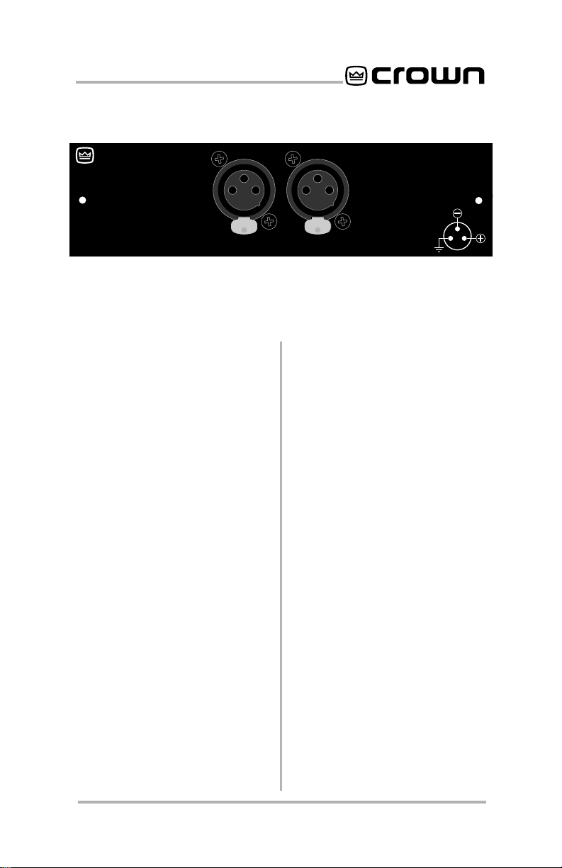
Fig. 1.1 P.I.P.-EDCb
1 Welcome
Thank you for purchasing the
Crown
modules are designed to
quickly install in the back of
many Crown amplifiers.
stands for “Programmable Input Processor.” Their versatile
features expand the capabilities of your amplifier and enable you to customize it for your
particular needs.
The
the-art error-driven compression, signal-driven input compression with adjustable threshold and a configurable subsonic (high-pass) filter to each
input of your amplifier. Three
conditions can cause a compressor to activate: (1) if the
compressor receives an “error” signal from the amplifier’s
input/output comparator (
circuitry, (2) if the input signal
exceeds its adjustable threshold, or (3) if an excessively large
P.I.P.-EDCb. P.I.P.
P.I.P.-EDCb
adds state-of-
P.I.P.
IOC
®
PUSH
INPUT
input signal level is sensed.
®
The compressor circuits activate ahead of all preamp circuitry resulting in low distortion.
Each channel’s compressor
can operate independently or
both channels can be tied together causing the compressors to track each other.
Balanced XLR connectors are
provided for quick connection.
Feature Summary
❏ Error-driven compression
for each channel.
❏ Variable threshold, signal-
driven compression for
each channel.
❏ User-selectable fast/slow
)
attack and release times.
❏ Each compressor can be
turned off.
❏ Variable subsonic (high-
pass) filter.
GND
3
12
Page 3
Page 4
P.I.P.–EDCb
ON
BCDCB
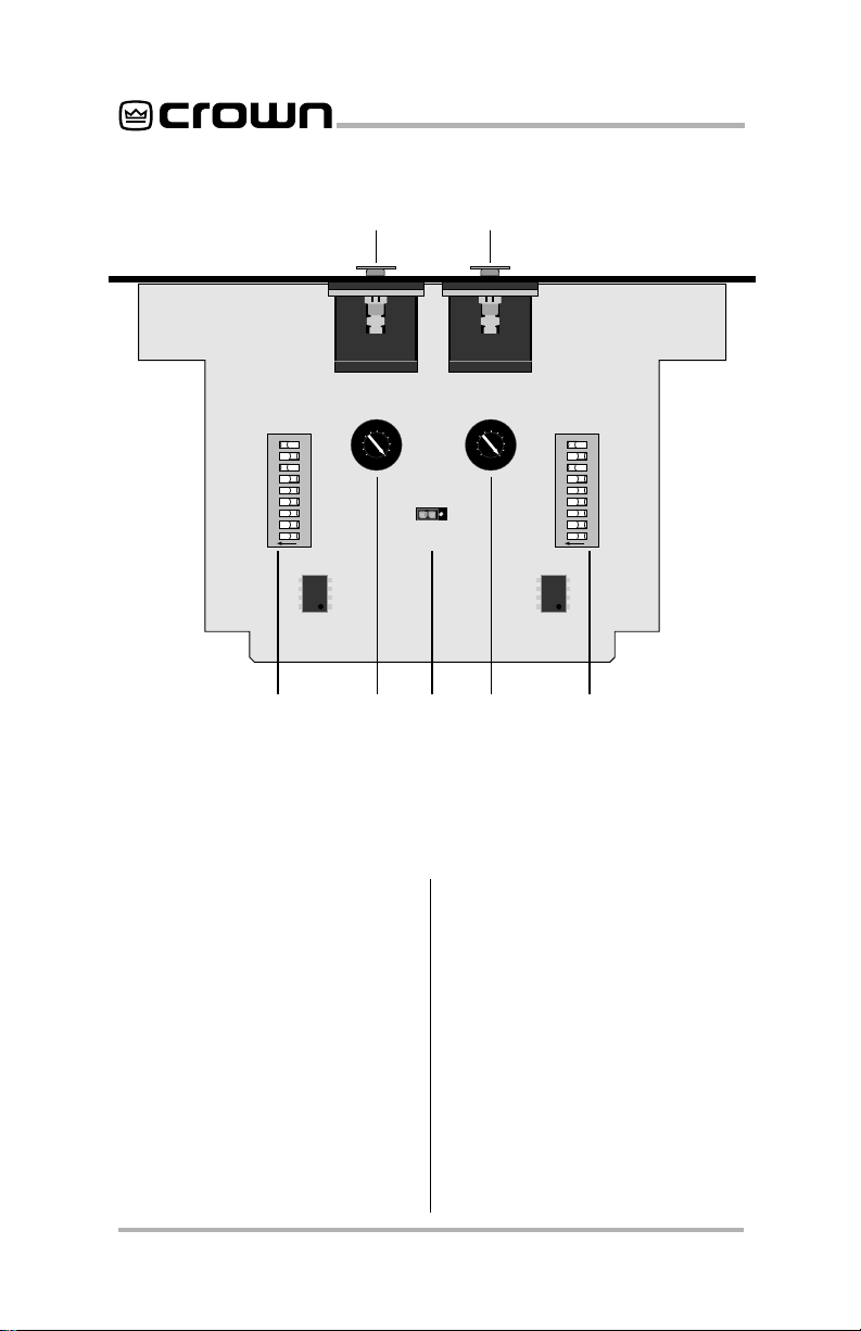
Fig. 2.1 P.I.P.-EDCb (Bottom View)
2 Facilities
S2
6789
12345
A
5
0
10
ON OFF
COMPRESSOR
TRACKING
A
5
S1
0
10
Z1
ON
6789
12345
A. Input Connectors
A balanced XLR connector is
provided for input to each channel. The pin assignments are
labeled on the face of the
Refer to your amplifier
Manual
for wiring details.
CAUTION: Input channel 2
should NOT be used in either
mono mode, and its level control should be turned off (fully
counterclockwise).
Page 4
P.I.P.
Owner’s
B. DIP Switches (S1, S2)
A nine-segment DIP switch is
provided for each channel.
Segments 1–6 select the subsonic corner frequency and
segments 7–9 configure the
compressor. S1 controls channel 1; S2 controls channel 2.
C. Compressor Threshold
Each channel’s compressor
threshold can be adjusted with
these controls. They set the
Page 5

P.I.P.–EDCb
maximum output voltage and
can be used to protect loudspeakers and listeners. When
turned to the maximum setting
(fully clockwise), the compressor responds only to the
channel’s
When set lower, the compres-
IOC
error signal.
sor responds to a maximum
audio level (see Figure 3.4).
D. Tracking Jumper (Z1)
Moving this jumper to the “ON”
position causes the compressors to track each other.
Page 5
Page 6

3 Installation
Before installing the
it should first be configured.
ule,
3.1
P.I.P.
Configuration
1. Set the corner frequency (–3 dB
frequency) for each subsonic
filter with DIP switches S1 and
S2 (see Figure 3.2). Notice that
the first six switch segments
control the corner frequency.
12345ON6789
Fig. 3.1 S1/S2 DIP Switch
2. Use DIP switches S1 and S2
to configure each compressor’s attack and release
times (fast or slow), or turn
each compressor off (see
P.I.P.
mod-
P.I.P.–EDCb
Compressor
Setting
Slow Attack / Slow Release
Slow Attack / Fast Release
Fast Attack / Slow Release
Fast Attack / Fast Release
Approximate Time
Attack Release
5 msec
900 msec
10 msec
220 msec
1.25 msec
900 msec
1.5 msec
220 msec
Fig. 3.3 Compressor Attack and
Release Times (Approximate)
Figure 3.2). Notice that the
last three DIP switch segments control attack and release times. The actual attack
time depends on the release
time. Figure 3.3 provides approximate times for each setting.
3. Adjust each channel’s com-
pressor threshold using the
compressor threshold pots
(see Figure 2.1, “C”). Each
Subsonic
Compressor
Page 6
Function
36 Hz Corner Frequency
32 Hz Corner Frequency
28 Hz Corner Frequency
Filter
24 Hz Corner Frequency
Slow Attack / Slow Release
Slow Attack / Fast Release
Fast Attack / Slow Release
Fast Attack / Fast Release
Compressor OFF
Fig. 3.2 S1/S2 DIP Switch Settings
DIP Switch (S1 or S2)
1
2
3
4
5
ON
ON
ON
ON
ON
ON
OFF
ON
OFF
ON
OFF
ON
OFF
ON
OFF
OFF
OFF
OFF
OFF
OFF
ON
OFF
ON
OFF
6
7
8
9
OFF
OFF
OFF
OFF
OFF
ON
ON
OFF
OFF
ON
OFF
ON
ON
Page 7

P.I.P.–EDCb
Mark
0
1
2
3
4
5
6
7
8
9
10
Macro-Tech 3600VZ
36x12
(Channel 1)
Max Sine
Wave RMS
Voltage
13.5
14
14.5
15
16
17
18
19
20
22
24
26
29
32
37
42
48
57
70
92
96
and
Watts into
8 Ohms
23
25
26
28
32
36
41
45
50
60
72
85
105
128
171
220
288
406
612
1058
1152
Max Sine
Wave RMS
Voltage
9.5
10
10.5
11
11.5
12
13
14
15
16
17
19
21
23
26
30
35
41
50
71
102
Fig. 3.4 Compressor Threshold Settings
All Others
Watts into
8 Ohms
11
12
14
15
17
18
21
25
28
32
36
45
55
66
85
113
153
210
313
630
1300
pot has a scale with ten marks
(or settings) which correspond
to the typical thresholds
shown in Figure 3.4.
P.I.P.’s
4. Move the
tracking
jumper (Z1) to the “ON” position to make the compressors
track each other. In the “OFF”
position, each compressor will
operate independently (refer
to Figure 2.1, “D”).
3.2 Installation Procedures
You may need a phillips screwdriver to remove the existing
P.I.P.
module or panel from your
amplifier.
CAUTION: Before connecting
this or any
P.I.P.
to your amplifier, it is important to turn its
level controls down, turn it off
Page 7
Page 8

P.I.P.–EDCb
and remove the AC power. Don’t
touch the circuitry. Even though
the amplifier is off, there could
still be enough energy remaining
to cause electric shock.
BACK PANEL
OF AMPLIFIER
P.I.P.
MODULE
Fig. 3.5 Installation into a
Standard P.I.P. Amplifier
FROM AMPLIFIER
Q43528-1
B
A
A
18 PIN (B)
B
20 PIN (A)
Fig. 3.6 PIP2 Input Adapter
Connection
BACK PANEL
OF PIP2
AMPLIFIER
PIP2 CONNECTOR
BOARD
P.I.P.
MODULE
Fig. 3.7 Installation into a
PIP2 Amplifier
1. Turn down the level controls
(full counterclockwise), turn off
the amplifier and unplug it from
the AC power source.
2. Remove the existing
P.I.P.
module or panel (two screws).
For
PIP2
amplifiers, this may
involve disconnecting the
P.I.P.
from a
PIP2
input adapter
(see Figures 3.6 and 3.7). If a
PIP2
input adapter is already
present, do not remove the
ribbon cables from the
adapter. Otherwise you will
have to reconnect them in the
next step.
Standard P.I.P. Amplifiers
3.
Align the edges of the
EDCb
in the
P.I.P.
P.I.P.–
card rails
and firmly push the unit in until
it is seated against the
mounting bracket (see Figure
3.5).
PIP2 Amplifiers:
PIP2
input adaptor. Crown part
(Requires a
number Q43528-1.) Connect
the
PIP2
input adapter to the
two input cables of the
amplifier (see Figure 3.6).
Notice that the
PIP2
input
adapter should be positioned
with the
P.I.P.
edge connector
on top and facing away from
the amplifier. The 20 pin cable
(A) is connected first, then the
18 pin cable (B) is connected.
Both ribbon cables should
extend below the
PIP2
input
adapter.
Next, insert the edge
connector of the
P.I.P.–EDCb
:
Page 8
Page 9

P.I.P.–EDCb
into the
Figure 3.7) and insert the
assembly into the
opening in the back of the
amplifier.
4. Secure the
the two screws and lock
washers provided. (The lock
washers are important
because they bond the
the chassis ground of the
amplifier.)
5. Connect input and output
wiring.
6. Plug in the amplifier and turn it
on. Adjust its level controls to a
desired setting.
Do not tamper with the circuitry.
Circuit changes made by unauthorized personnel, or unauthorized circuit modifications are not
allowed.
Remember: Crown is not liable
for any damage resulting from
overdriving other components in
your sound system.
PIP2
input adapter (see
P.I.P.–EDCb
P.I.P.
with
P.I.P.
to
CAUTION: IF PHONE JACKS
ARE PROVIDED ON THE AMPLIFIER BACK PANEL, DO
NOT USE THEM AS INPUTS
WITH THIS
The amplifier phone jacks are in
parallel with the
they can be used to “daisy chain”
the inputs of several amplifiers. If
you do this, remember that the
signal feeding the other amplifiers will be filtered and compressed too.
Important: If the amplifier is used
in either Bridged-Mono or Parallel-Mono mode, you
the Ch. 2 amplifier level control
off (fully counterclockwise). The
input and level control of Ch. 2
are not defeated in mono mode
so any signal applied to Ch. 2 will
beat against the signal in Ch. 1.
Refer to the amplifier
Manual
about Bridged-Mono or ParallelMono modes of operation.
P.I.P.
INSTALLED.
P.I.P.
outputs, so
must turn
Reference
for more information
Page 9
Page 10

Electronic image for this figure
were not included due to quality
considerations. Please refer to
the printed documentation.
P.I.P.–EDCb
Page 10
Only one channel shown.
Page 11

P.I.P.–EDCb
Electronic image for this figure
were not included due to quality
considerations. Please refer to
the printed documentation.
Notes:
1. All resistor values are in ohms,
1
/8 W, 1% unless otherwise specified.
2. All capacitor values are in micro-farads unless otherwise specified.
Page 11
Page 12

4 Specifications
Note: All specifications are referenced to a 0.775 volt input signal.
Signal to Noise: Greater than 95
dB from subsonic filter corner
frequency to 20 kHz.
Frequency Response: ±0.1 dB
from 70 Hz to 30 kHz with subsonic filter corner frequency set
to 36 Hz. +0, –3 dB from subsonic filter corner frequency to
30 kHz.
Harmonic Distortion (THD):
Less than 0.01% THD at 1 kHz.
Common Mode Rejection:
Greater than 65 dB at 1 kHz.
Crosstalk: Less than 0.5 mV at
20 kHz.
Connectors: 3-pin female XLR
for each input.
Input Impedance: Nominally 30
K ohms balanced. 15 K ohms
unbalanced.
Maximum Input Level: 35 VAC.
Maximum Output Level:
+18
dB with 600 ohm load.
Nominal Gain: Unity ±0.5 dB.
3
Dimensions: 6
/8 x 17/8 x 37/8 in.
(16.2 x 4.8 x 9.8 cm).
For Technical Support contact:
Crown Audio Division Technical Support Group
Phone: 800-342-6939 (North America, Puerto Rico and Virgin Islands) or 219-294-8200
Plant 2 SW, 1718 W. Mishawaka Rd., Elkhart, Indiana 46517 U.S.A.
Fax: 219-294-8301 Fax Back (North America only): 800-294-4094 or 219-293-9200
Fax Back (International): 219-294-8100
Internet: http://www.crownaudio.com
 Loading...