

Page 1
P.I.P.-CLP
© 2005 by Crown Audio®, Inc., 1718 W. Mishawaka Rd. 46517-9439 U.S.A. Telephone: 574-294-8000. Fax: 574-294-8329. PIP modules are produced by Crown
Audio, Inc. Trademark Notice: Studio Reference, PIP, PIP2 are trademarks and
Crown, Crown Audio, Amcron, Macro-Tech, Com-Tech, IOC and P.I.P. are registered trademarks of Crown International. Other trademarks are the property of their
respective owners.
Obtaining Other Language Versions:
To obtain information in another language about the use of this product, please
contact your local Crown Distributor. If you need assistance locating your local
distributor, please contact Crown at 574-294-8200.
Note: The information provided in this manual was deemed accurate as of the
publication date. However, updates to this information may have occurred. To
obtain the latest version of this manual, please visit the Crown website at www.
crownaudio.com.
Printed on
recycled paper.
101641-5
8/05
Page 2

P.I.P.-CLP
Page 2
Reference Manual
Page 3
P.I.P.-CLP
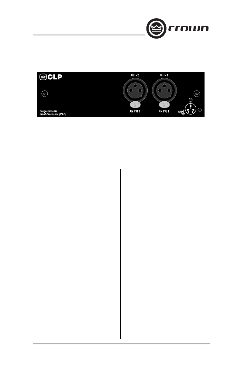
Fig. 1 The P.I.P.-CLP
1 Welcome
Thank you for purchasing the
Crown P.I.P.®-CLP accessory.
PIP™ modules are designed to
install easily into the back panel
of many Crown amplifiers. PIP
stands for “Programmable Input
Processor.” Their versatile features expand the capabilities of
your amplifi er and enable you to
customize it for your particular
needs.
The P.I.P.-CLP is designed to
detect and reduce overload in
the output stages of Crown Com-
Tech,® Macro-Tech® and Studio
Reference™ amplifi ers. As the am-
plifi er output reaches the clipping
threshold, an internal error signal
activates the P.I.P.-CLP which
reduces the input gain of the amplifi er at a fast yet audibly undetectable rate. This feature provides
an additional 13 dB of input signal
headroom, making it virtually impossible to overload the amplifi er.
By following the simple installa-
tion instructions in this manual,
you will expand your amplifi er to
include these capabilities.
Specifi cations
Connectors: Two female XLR inputs; pin 1 is ground, pin 2 is positive (+) and pin 3 is negative (–).
Signal-to-Noise: –85 dB (referenced to 0.775 volts) equivalent
input noise from 20 Hz to 20 kHz.
Frequency Response: Flat
±0.2 dB from 20 Hz to 20 kHz.
Input Impedance (Nominal):
20 k ohms balanced and 10 k
ohms unbalanced.
Limiter Action: Range of limiter action is restricted to 13 dB
(nominal). Threshold is set to
the point of amplifier overload.
Compression attack time is 0.35
milliseconds; decay time is 160
milliseconds.
Reference Manual
Page 3
Page 4
2 Installation
You may need a Phillips screwdriver to remove the existing PIP
module or panel from your amplifi er.
CAUTION: Before connecting
this or any PIP to your amplifi er, it is important to turn the
amplifi er's level controls down,
turn it off and remove the AC
power. Don’t touch the circuitry.
Even though the amplifier is
off, there could still be enough
energy remaining to cause electric shock.
1. Turn down the level controls
(full counterclockwise), turn
off the amplifi er and unplug it
from the AC power source.
2. Remove the existing PIP
module or panel (two screws).
For PIP2TM amplifi ers, this
may involve disconnecting the
PIP from a PIP2 input adapter
(see Figures 2.2 and 2.3). If a
PIP2 input adapter is already
present, do not remove
the ribbon cables from the
P.I.P.-CLP
adapter. Otherwise you will
have to reconnect them in the
next step.
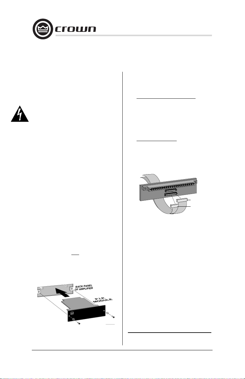
3. Standard PIP Amplifi ers: Align
the edges of the P.I.P.–CLP
in the PIP card rails and
fi rmly push the unit in until it is
seated against the mounting
bracket (see Figure 2.3).
PIP2 Amplifi ers*: (Requires
a PIP2 input adaptor, Crown
part number Q43528-1.) Connect the PIP2 input adapter
FROM AMPLIFIER
PIP2 ADAPTER
B
A
B
A
18 PIN (B)
20 PIN (A)
Fig. 2.2 PIP2 Input Adapter
Connection
to the two input cables of the
amplifi er (see Figure 2.2).
Notice that the PIP2 input
adapter should be positioned
with the PIP edge connector
on top and facing away from
the amplifi er. The 20-pin cable
(A) is connected fi rst, then the
18-pin cable (B) is connected.
Both ribbon cables should
extend below the PIP2 input
adapter.
Fig. 2.1 Installation into a
Standard PIP Amplifi er
Page 4
* Note: The P.I.P.– CLP is not compatible
with Crown CTs amplifi ers.
Reference Manual
Page 5

P.I.P.-CLP
Next, insert the edge con-
nector of the P.I.P.–CLP into
the PIP2 input adapter (see
Figure 2.3) and insert the assembly into the PIP opening in
the back of the amplifi er.
4. Tighten the two PIP mounting
thumbscrews.
5. Reconnect input wiring.
6. Plug in the amplifi er and turn
it on. Adjust its level controls
to a desired setting.
Do not tamper with the circuitry.
Circuit changes made by unauthorized personnel, or unauthorized circuit modifi cations, are not
allowed.
Fig. 2.3 Installation into a
PIP2 Amplifi er
Remember: Crown is not liable for
any damage resulting from overdriving other components in your
sound system.
Crown Audio
Technical Support / Factory Service
1718 W. Mishawaka Rd., Elkhart,
Indiana 46517 U.S.A.
Telephone: 574-294-8200
800-342-6939
(North America,
Puerto Rico, and
Virgin Islands only)
Facsimile: 574-294-8301
(Technical Support)
574-294-8124
(Factory Service)
Internet:
http://www.crownaudio.com
CAUTION: If your amplifier is
equipped with 1/4-inch phone jacks
on the back panel, do not connect
input signals to them while the
P.I.P.-CLP is installed. Input signals connected to the phone jacks
will be altered by the output circuitry of the P.I.P.-CLP and result
in a distorted signal.
Reference Manual
Page 5
Page 6

3 Optional Modifi cations
Some amplifi ers are perceived to
be louder than others while they
actually deliver equal or less power. Such an amplifi er is typically
set up to clip the input signal, or it
uses built-in compressors that reduce dynamic range and increase
average signal levels. This is fi ne if
it’s what you want. But if you don’t
want it and you can’t get rid of it,
it’s a problem. This is why Crown
amplifi ers are designed to deliver
maximum power without distortion
or hidden compressors to make
them sound louder.
But what if you prefer the sound
and apparent loudness of a compressed audio signal? In this
P.I.P.-CLP
case, the P.I.P.-CLP can be modifi ed to simulate the same effect.
Normally, the P.I.P.-CLP protects
loudspeakers from damage that
can result from a clipped signal.
For maximum protection, the
PIP’s default configuration provides super-fast attack and decay
times with an infi nite compression
ratio.
Modifi cations to the PIP can slow
the attack and decay times to allow some clipping, which many
listeners perceive as a louder
sound. (This short-term clipping
does not damage loudspeakers.)
B
Fig. 3 Resistor and Capacitor Locations for Modifi cations A and B
Page 6
Reference Manual
Page 7

P.I.P.-CLP
There are two possible modifi cations; the fi rst increases the attack
time while the second doubles
both attack and decay times.
Modifi cation A will increase the
attack time from the original 0.35
milliseconds to 5 milliseconds. It
does not affect the original decay
time which is 160 milliseconds.
1. Replace the two 10 k ohm
resistors marked R117 and
R217 with 121 k ohm resistors.
Modification B will further increase the attack time beyond that
produced by modifi cation A, and
will also increase the decay time.
If you choose to make modifi cation B, you must also make modifi cation A. Together, modifi cations
A and B produce an attack time of
10 milliseconds and a decay time
of 320 milliseconds.
1. Perform modifi cation A.
2. Replace the two 0.1 µf capacitors C103 and C203 with 0.22
µf capacitors.
Reference Manual
Page 7
Page 8

P.I.P.-CLP
Page 8
Reference Manual
Page 9

P.I.P.-CLP
Reference Manual
J 0225-3
Rev. G
Page 9
Page 10

P.I.P.-CLP
Page 10
Reference Manual
Page 11

P.I.P.-CLP
Reference Manual
Page 11
Page 12

P.I.P.-CLP
For Technical Support contact:
Crown Audio Technical Support Group
Phone: 800-342-6939 (North America, Puerto Rico and Virgin Islands) or 574-294-8200
Page 12
1718 W. Mishawaka Rd., Elkhart, Indiana 46517 U.S.A.
Fax: 574-294-8301 Internet: http://www.crownaudio.com
Reference Manual
 Loading...