

Page 1
P.I.P.–BP1X & P.I.P.
–BP1C
OUT IN IN
PUSH
Programmable
Input Processor (P.I.P.)
©2000 by Crown International, Inc., P.O. Box 1000, Elkhart, IN 465151000 U.S.A. Telephone: 219-294-8000. Fax: 219-294-8329. Trademark
Notice:
trademarks of Crown International, Inc. Other trademarks are the
property of their respective owners.
PIP™ is a trademark, and Crown
CH-2 CH-1
PUSH
®
and
OUT
®
IOC
are registered
GND
12
3
Printed on
recycled paper.
127924-1A
10/00
Page 2

P.I.P.–BP1X & P.I.P.–BP1C
Page 2
Reference Manual
Page 3

P.I.P .–BP1X & P.I.P.–BP1C
OUT IN IN
PUSH
Programmable
Input Processor (P.I.P.)
CH-2 CH-1
Fig. 1.1 P.I.P.–BP1X Shown
1 Welcome
Congratulations on your purchase of
Crown’s
PIP™
quickly install in the back of many
Crown amplifiers.
grammable Input Processor.” Each
PIP
pabilities of your amplifier , enabling you
to customize it for your particular
needs.
The
versatile stereo Band-Pass processors that plug into any
Crown amplifier . The
XLR connectors and the
uses a removable barrier block. Each
channel of the PIP is completely independent from the other and combines
the functions of a low-pass filter , a highpass filter , vented-speaker box equalization, horn equalization and
compression.
DIP switches and convenient jumper
blocks make it easy to configure any of
its powerful operating features.
P.I.P.–BP1X or P.I.P.–BP1C
modules are designed to
PIP
stands for “Pro-
has features that expand the ca-
P.I.P.–BP1X and P.I.P.–BP1C
PIP
P.I.P.–BP1X
are
-capable
uses
P.I.P.–BP1C
OUT
PUSH
Features
❏ Variable 24-dB/octave (4th order)
.
Butterworth low-pass filter.
❏ Variable 24-dB/octave (4th order)
Butterworth high-pass filter.
❏ Variable 12-dB/octave (2nd order)
low-frequency filter with Q=2 for
vented box equalization.
❏ Variable 6-dB/octave high-fre-
quency shelving network with variable 12-dB/octave high-frequency
low-pass filter for constant-directivity horn equalization.
❏ Variable threshold, feedback/error-
driven compressor/limiter with infinite compression ratio.
❏ Configurable compressor control
path.
❏ Configurable “daisy chain” outputs.
❏ Balanced 3-pin XLR connectors or
quick-disconnect removable barrier block connectors (depending
on model) for input and daisy chain
outputs.
GND
3
12
Reference Manual
Page 3
Page 4
P.I.P .–BP1X & P.I.P.–BP1C
Programmable
Input Processor (P .I.P.)
BYPASS
NORM
OUT IN IN
PUSH
CH-2 CH-1
S200
S204
OFF
OFF
S205
12345
678910
S209
12345
678
12345
678
ON
S206
OFF
OFF
S207
12345
678910
12345
678
12345
678
ON
S208
S202
OFF
OFF
12345
12345
678
678
OFF
OFF
12345
12345
678
678
S203
S201
CH1 CH2 CH1 CH2
OUT
PUSH
AI
BABI
3
GND
12
BYPASS
NORM
S108
S106
OFF
OFF
S107
12345
678910
12345
678
12345
678
ON
S104
OFF
OFF
S105
12345
678910
S109
12345
678
12345
678
ON
S102 S100
OFF
OFF
12345
678
OFF
OFF
12345
678
S101
S103
12345
678
12345
678
Page 4
C G
DF E H H C E
G FD
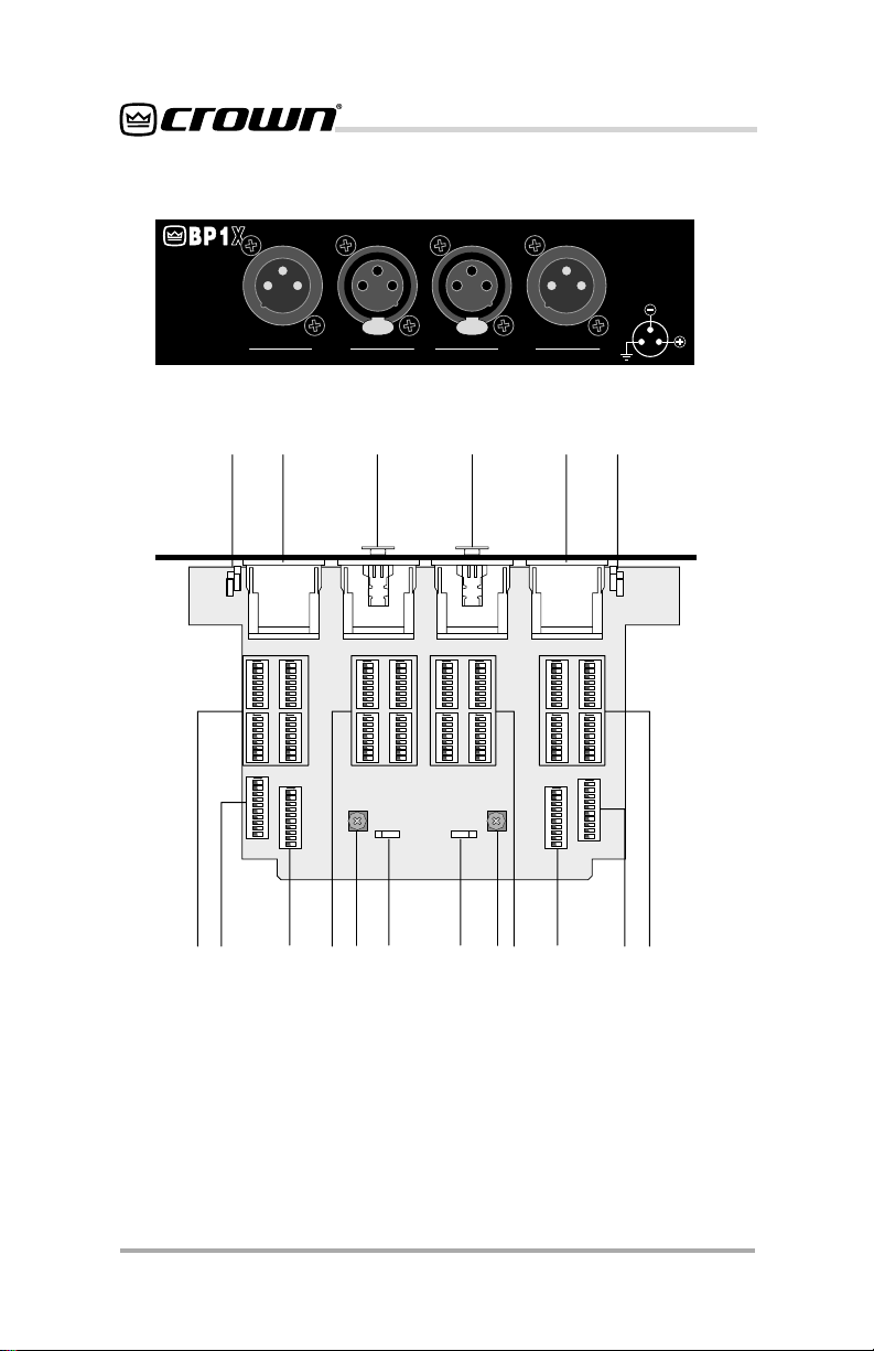
Fig. 2.1 P .I.P.-BP1X
Front & Bottom Views
Reference Manual
Page 5

P.I.P .–BP1X & P.I.P.–BP1C
2 Controls,Connectors
& Setup
A/B. Connectors
Balanced 3-pin XLR or quick-disconnect removable barrier block connectors are provided for the inputs and
outputs. The
with XLR Jacks: a female XLR for the
input connector and a male XLR for
the daisy chain output. These connectors are wired for pin 2 = Hot. The
P.I.P.-BP1C
connect removable barrier block connectors; mating connectors are
supplied to allow the user to quickly
disconnect an input or output and
move it to the other channel. These
connectors are wired pin1=Hot. (See
Section 3 for input and output wiring
examples.)
C. Low-Pass Filter DIP Switches
The input signal is processed first by a
4th-order (24-dB/octave) low-pass
filter network with a Butterworth response characteristic. Four eight-segment DIP switches (S100,S101,S102
and S103 for channel 1),(S200,S201,
S202 and S203 for channel 2) select
the low-pass filter frequency at which
the output is –3-dB down from the input. (See Figure 2.2 for a complete
table of frequencies and settings and
Figure 2.3 for sample frequency-response graphs.) Note that all four DIP
switches must use the same settings
for the response to be correct. These
DIP switches are factory-set to 20 kHz.
D. High-Pass Filter DIP
Switches
The signal is processed next by a 4thorder (24-dB/octave) high-pass filter
network with a Butterworth response
characteristic. Four eight-segment DIP
switches(S104,S105,S106 and S107
P.I.P.-BP1X
is supplied with quick-dis-
is supplied
for Channel 1), (S204,S205,S206 and
S207 for Channel 2) select the high
pass filter frequency at which the output is –3-dB down from the input. (See
Figure 2.2 for a complete table of frequencies and settings and Figure 2.4
for sample frequency-response
graphs.) Note that all four DIP switches
must use the same settings for the response to be correct. These DIP
switches are factory-set to 23 Hz.
E. Low-Frequency Equalization
DIP Switches
Following the high-pass filter is a 6thorder loudspeaker equalization feature. A ten-segment DIP switch (S108
for Channel 1); (S208 for Channel 2)
sets the +6 dB boost frequency of the
vented-box equalization filter. Note:
(Switch 7 is not active and can be set
to either the“ON”or“OFF’) position. This
feature is used for loudspeakers that
have been designed as a 6th-order
system and require 2nd-order equalization to achieve optimum performance. The filter uses the Sallen-Key
non-inverting second-order high-pass
topology. The loudspeaker manufacturer determines the frequency to
which this filter should be set. Low-Frequency Equalizaion is factory-set to
Flat (Figure 2.5 shows a complete listing of equalization points and the corresponding switch positions; Figure
2.6 shows typical response curves for
the filter).
F. Constant-Directivity Horn
Equalization DIP Switches
This ten-segment DIP Switch (S109 for
Channel 1) ); (S209 for Channel 2) sets
both the +3-dB shelving frequency
and the –3-dB low-pass roll-off frequency of the constant-directivity horn
equalization filter. Constant-directivity
horns have an inherent roll-off in their
Reference Manual
Page 5
Page 6

P.I.P .–BP1X & P.I.P.–BP1C
response that must be corrected electronically by this filter. The actual response is determined by the
combination of a stage of first-order
boost (controlled by switches 8, 9, and
10) and a stage of second-order highfrequency roll off (controlled by
switches 1-6),
Note: switch 7 is not active and can be
set at either the“ON” or“OFF”position.
The loudspeaker manufacturer determines the frequencies to which these
switches should be set. Constant-Directivity Horn Equalizaion is factoryset to Flat. Refer to Figure 2.7a for
–3-dB low pass roll-off frequency settings and corresponding switch positions. Refer to Figure 2.7a for +3-dB
shelving frequency settings and corresponding switch positions. Figure
2.8 shows sample response curves.
G. Compressor Threshold
Potentiometer
The compressor occurs in the signal
path after the filters and equalizers. A
variable-threshold signal-driven compressor is provided and by default is
ON and is error driven. With errordriven compression, the compressor
will activate if the amplifier clips, regardless of the output signal. Errordriven compression is useful when the
possibility of over-driving the amplifier
by several dB is present and the resulting distortion is unacceptable.
Reducing the output voltage at which
the compressor will activate is useful
for applications where driver and/or
system protection is desired. Compression will then limit the output voltage to a predetermined level, even as
the input to the amplifier is increased.
Attack time is 10 msec and release
time is 360 msec. The compressor
has an infinite compression ratio,
meaning that when the threshold is
Page 6
reached, an increase in input level will
not result in a change in output level.
The range of compression is 16 dB. If
the input is driven more than 16 dB
over the threshold, the portion of the
signal over 16 dB will be passed linearly. At that point, the next limit to
output will be amplifier clipping. (See
Figure 2.9 for a table of potentiometer
settings and the corresponding voltage and power outputs from the amplifier.)
H. Compressor Control
This two-position jumper block controls the feedback path that will drive
the compressors. The compressor in
a certain channel can be controlled by
the error amplifier of that channel, the
error amplifier of the other channel, or
neither (compressor turned off). When
the compressor is turned off, no amplifier condition, whether it is high output
voltage or clipping, will cause the compressor to activate. To tur n the compressor off, place the jumper on only
one pin of the jumper block.
I. Daisy Output Jumpers
These two-position jumpers are used
to select between sending the processed signal (NORM) and the unprocessed signal (BYPASS) to the
daisy chain outputs. Sending the processed signal to the daisy chain outputs will allow two or more amplifiers to
run off of the same processed signal,
so only one
be used (the signal needs only to be
processed once for all of the amplifiers
that need the signal). Sending the unprocessed signal to the daisy chain
outputs will enable the use of other
P.I.P.–BP1
switch settings or the use of other
modules to perform different functions
on the same input signal. Both jumpers
of each channel must be in the same
position for correct operation.
P.I.P.–BP1
modules with different DIP
would have to
P.I.P.
Reference Manual
Page 7
P.I.P .–BP1X & P.I.P.–BP1C
J. Input Ground Lift Jumper
The unit is shipped from the factory
with pin 1 of each input XLR connected
to signal ground through independent
0-ohm resistors. If hum problems are
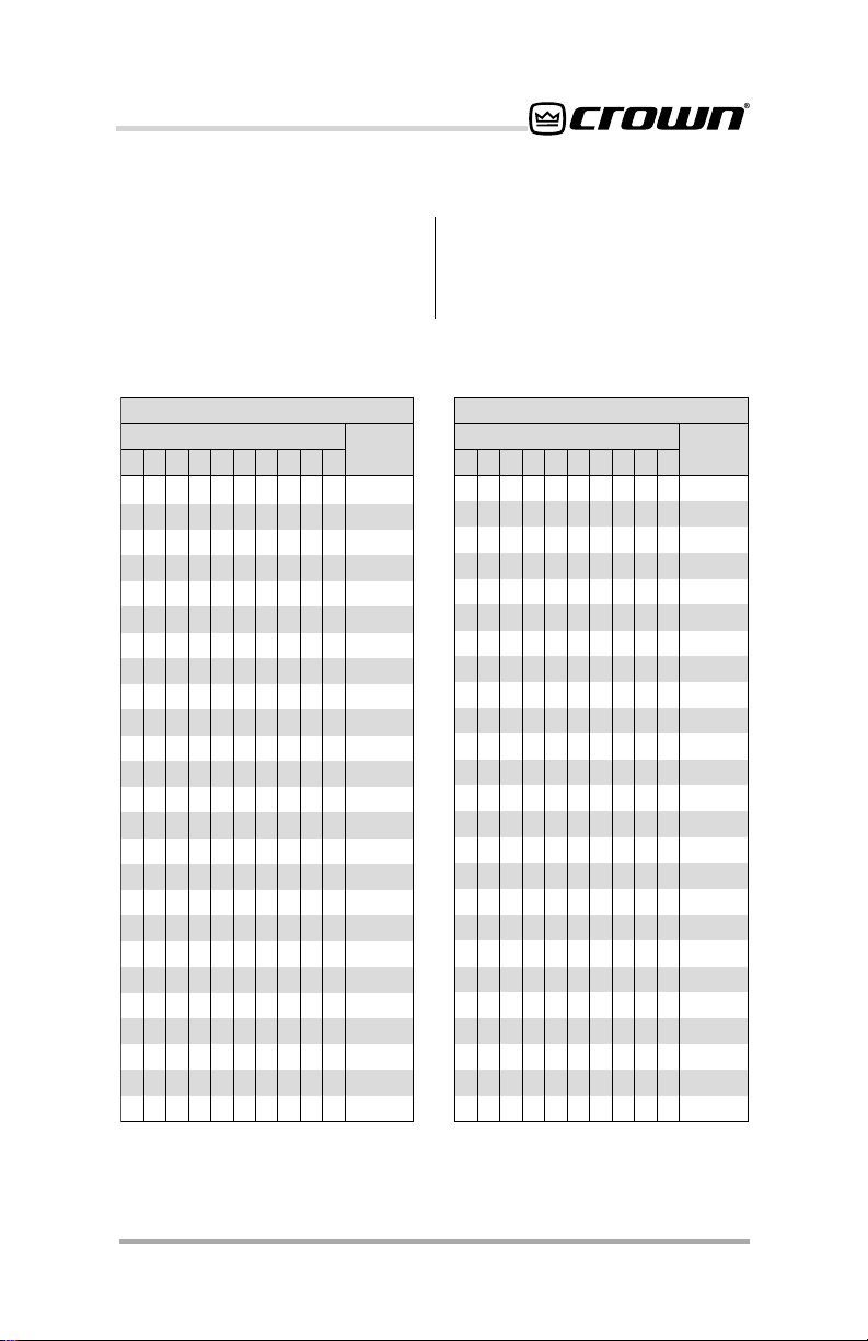
Low Pass Frequencies
SEICNEUQERFFFOTUC
sgnitteShctiwS
1 2 3 4 5 6 7 8 9 01
NONONONONONONONO
FFO NO NO NO NO NO NO NO
NOFFONONONONONONO
FFO FFO NO NO NO NO NO NO
NONOFFONONONONONO
FFO NO FFO NO NO NO NO NO
NOFFOFFONONONONONO
FFO FFO FFO NO NO NO NO NO
NONONOFFONONONONO
FFO NO NO FFO NO NO NO NO
NOFFONOFFONONONONO
FFO FFO NO FFO NO NO NO NO
NONOFFOFFONONONONO
FFO NO FFO FFO NO NO NO NO
NOFFOFFOFFONONONONO
FFO FFO FFO FFO NO NO NO NO
NONONONOFFONONONO
FFO NO NO NO FFO NO NO NO
NOFFONONOFFONONONO
FFO FFO NO NO FFO NO NO NO
NONOFFONOFFONONONO
FFO NO FFO NO FFO NO NO NO
NOFFOFFONOFFONONONO
FFO FFO FFO NO FFO NO NO NO
NONONOFFOFFONONONO
------
--- ---
------
--- ---
------
--- ---
------
--- ---
------
--- ---
------
--- ---
------
--- ---
------
--- ---
------
--- ---
------
--- ---
------
--- ---
------
--- ---
------
)zH(
00002
00851
00321
00601
0008
8227
2146
7095
0004
3873
7453
6833
7603
7492
2082
1072
0081
5771
1271
3861
0061
7651
5251
4941
2331
experienced, the appropriate resistor
may be removed. This will then connect pin 1 of the XLR from that channel
to signal ground through an 82-ohm
resistor in parallel with a 0.1µF capacitor.
ssaPwoL
ycneuqerF
1 2 3 4 5 6 7 8 9 01
FFONONOFFOFFONONONO
NO FFO NO FFO FFO NO NO NO
FFOFFONOFFOFFONONONO
NO NO FFO FFO FFO NO NO NO
FFONOFFOFFOFFONONONO
NO FFO FFO FFO FFO NO NO NO
FFOFFOFFOFFOFFONONONO
NO NO NO NO NO FFO NO NO
FFONONONONOFFONONO
NO FFO NO NO NO FFO NO NO
FFOFFONONONOFFONONO
NO NO FFO NO NO FFO NO NO
FFONOFFONONOFFONONO
NO FFO FFO NO NO FFO NO NO
FFOFFOFFONONOFFONONO
NO NO NO FFO NO FFO NO NO
FFONONOFFONOFFONONO
NO FFO NO FFO NO FFO NO NO
FFOFFONOFFONOFFONONO
NO NO FFO FFO NO FFO NO NO
FFONOFFOFFONOFFONONO
NO FFO FFO FFO NO FFO NO NO
FFOFFOFFOFFONOFFONONO
NO NO NO NO FFO FFO NO NO
FFONONONOFFOFFONONO
sgnitteShctiwS
------
--- ---
------
--- ---
------
--- ---
------
--- ---
------
--- ---
------
--- ---
------
--- ---
------
--- ---
------
--- ---
------
--- ---
------
--- ---
------
--- ---
------
SEICNEUQERFFFOTUC
ssaPwoL
ycneuqerF
)zH(
8031
9721
7521
1121
1911
7611
9411
277
467
057
747
037
327
417
707
866
366
556
946
736
136
426
916
755
355
Figure 2.2a Low Pass Cutoff Frequencies
Note: Switches 9 and 10 are not active.
“---” denotes switch may be set to either the
ON or OFF position.
Reference Manual
Page 7
Page 8
P.I.P .–BP1X & P.I.P.–BP1C
Low Pass Frequencies
sgnitteShctiwS
1 2 3 4 5 6 7 8 9 01
NOFFONONOFFOFFONONO
FFO FFO NO NO FFO FFO NO NO
NONOFFONOFFOFFONONO
FFO NO FFO NO FFO FFO NO NO
NOFFOFFONOFFOFFONONO
FFO FFO FFO NO FFO FFO NO NO
NONONONOFFOFFONONO
FFO NO NO FFO FFO FFO NO NO
NOFFONOFFOFFOFFONONO
FFO FFO NO FFO FFO FFO NO NO
NONOFFOFFOFFOFFONONO
FFO NO FFO FFO FFO FFO NO NO
NOFFOFFOFFOFFOFFONONO
FFO FFO FFO FFO FFO FFO NO NO
NONONONONONOFFONO
FFO NO NO NO NO NO FFO NO
NOFFONONONONOFFONO
FFO FFO NO NO NO NO FFO NO
NONOFFONONONOFFONO
FFO NO FFO NO NO NO FFO NO
NOFFOFFONONONOFFONO
FFO FFO FFO NO NO NO FFO NO
NONONOFFONONOFFONO
FFO NO NO FFO NO NO FFO NO
NOFFONOFFONONOFFONO
------
--- ---
------
--- ---
------
--- ---
------
--- ---
------
--- ---
------
--- ---
------
--- ---
------
--- ---
------
--- ---
------
--- ---
------
--- ---
------
--- ---
------
SEICNEUQERFFFOTUC
ssaPwoL
ycneuqerF
)zH(
845
445
535
135
625
225
105
894
394
094
384
084
674
374
623
423
223
123
813
713
513
413
603
403
303
1 2 3 4 5 6 7 8 9 01
FFOFFONOFFONONOFFONO
NO NO FFO FFO NO NO FFO NO
FFONOFFOFFONONOFFONO
NO FFO FFO FFO NO NO FFO NO
FFOFFOFFOFFONONOFFONO
NO NO NO NO FFO NO FFO NO
FFONONONOFFONOFFONO
NO FFO NO NO FFO NO FFO NO
FFOFFONONOFFONOFFONO
NO NO FFO NO FFO NO FFO NO
FFONOFFONOFFONOFFONO
NO FFO FFO NO FFO NO FFO NO
FFOFFOFFONOFFONOFFONO
NO NO NO FFO FFO NO FFO NO
FFONONOFFOFFONOFFONO
NO FFO NO FFO FFO NO FFO NO
FFOFFONOFFOFFONOFFONO
NO NO FFO FFO FFO NO FFO NO
FFONOFFOFFOFFONOFFONO
NO FFO FFO FFO FFO NO FFO NO
FFOFFOFFOFFOFFONOFFONO
NO NO NO NO NO FFO FFO NO
FFONONONONOFFOFFONO
NO FFO NO NO NO FFO FFO NO
FFOFFONONONOFFOFFONO
sgnitteShctiwS
------
--- ---
------
--- ---
------
--- ---
------
--- ---
------
--- ---
------
--- ---
------
--- ---
------
--- ---
------
--- ---
------
--- ---
------
--- ---
------
--- ---
------
SEICNEUQERFFFOTUC
ssaPwoL
ycneuqerF
)zH(
203
003
892
692
592
082
972
872
772
472
372
272
172
562
462
362
262
062
952
852
752
232
132
032
922
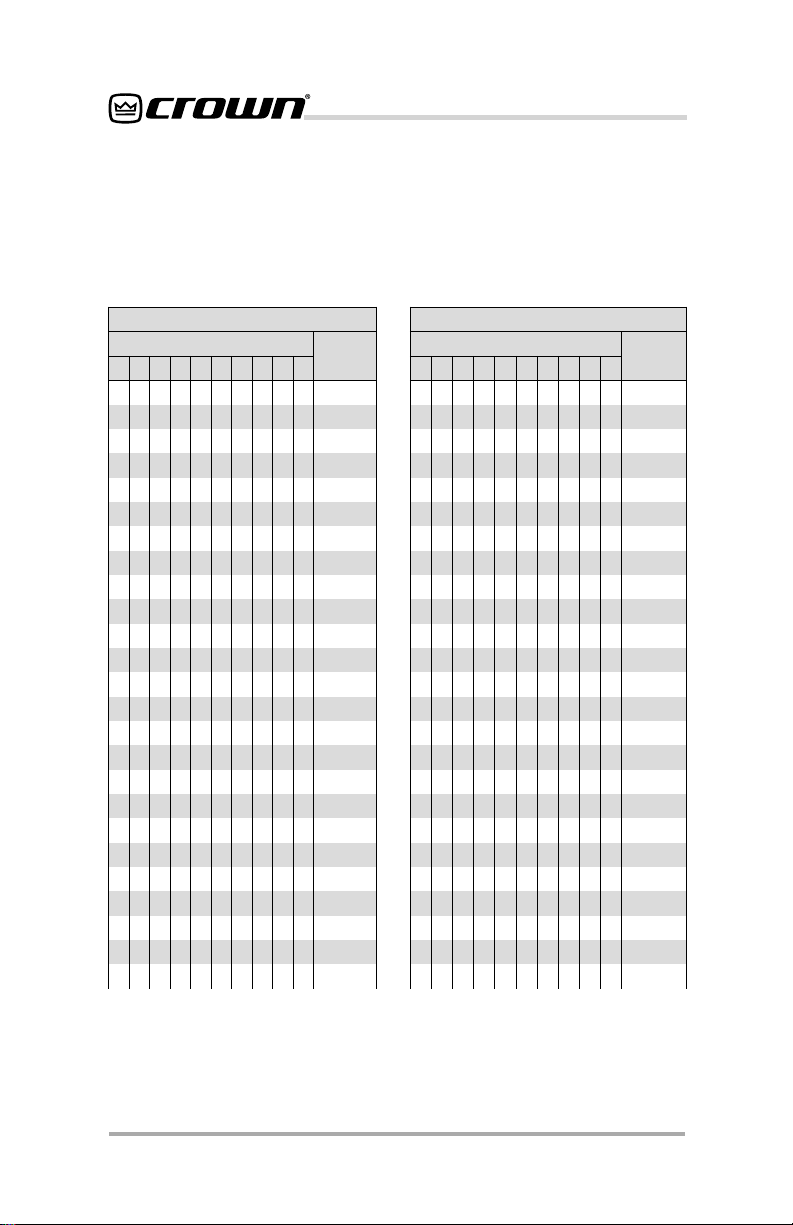
Figure 2.2b Low Pass Cutoff Frequencies
Note: Switches 9 and 10 are not active.
“---” denotes switch may be set to either the
ON or OFF position.
Page 8
Reference Manual
Page 9

P.I.P .–BP1X & P.I.P.–BP1C
Low Pass Frequencies
sgnitteShctiwS
1 2 3 4 5 6 7 8 9 01
NONOFFONONOFFOFFONO
FFO NO FFO NO NO FFO FFO NO
NOFFOFFONONOFFOFFONO
NO NO NO FFO NO FFO FFO NO
NOFFONOFFONOFFOFFONO
FFO FFO NO FFO NO FFO FFO NO
NONOFFOFFONOFFOFFONO
FFO NO FFO FFO NO FFO FFO NO
NOFFOFFOFFONOFFOFFONO
NO NO NO NO FFO FFO FFO NO
FFONONONOFFOFFOFFONO
NO FFO NO NO FFO FFO FFO NO
NONOFFONOFFOFFOFFONO
NO FFO FFO NO FFO FFO FFO NO
NONONOFFOFFOFFOFFONO
NO FFO NO FFO FFO FFO FFO NO
NONOFFOFFOFFOFFOFFONO
NO FFO FFO FFO FFO FFO FFO NO
NONONONONONONOFFO
NO NO FFO NO NO NO NO FFO
FFOFFOFFONONONONOFFO
NO NO NO FO NO NO NO FFO
FFOFFONOFFONONONOFFO
NO FFO FFO FFO NO NO NO FFO
NONONONOFFONONOFFO
NO NO FFO NO FFO NO NO FFO — —
------
--- ---
------
--- ---
------
--- ---
------
--- ---
------
--- ---
------
--- ---
------
--- ---
------
--- ---
------
--- ---
------
--- ---
------
--- ---
------
--- ---
------
SEICNEUQERFFFOTUC
ssaPwoL
ycneuqerF
)zH(
822
722
622
122
022
912
812
712
612
802
702
602
402
302
991
891
691
591
231
131
031
921
821
721
421
321
1 2 3 4 5 6 7 8 9 01
FFOFFOFFONOFFONONOFFO
NO NO NO FFO FFO NO NO FFO
NONOFFOFFOFFONONOFFO
FFO FFO FFO FFO FFO NO NO FFO
NONONONONOFFONOFFO
NO FFO NO NO NO FFO NO FFO
NOFFOFFONONOFFONOFFO
NO NO NO FFO NO FFO NO FFO
NONOFFOFFONOFFONOFFO
NO NO NO NO FFO FFO NO FFO
FFONONONOFFOFFONOFFO
NO FFO FFO NO FFO FFO NO FFO
NONONOFFOFFOFFONOFFO
NO NO FFO FFO FFO FFO NO FFO
NONONONONONOFFOFFO
FFO NO NO NO NO NO FFO FFO
NONONOFFONONOFFOFFO
FFO FFO NO FFO NO NO FFO FFO
NONONONOFFONOFFOFFO
NO FFO FFO NO FFO NO FFO FFO
NOFFONOFFOFFONOFFOFFO
NO NO NO NO NO FFO FFO FFO
NOFFONONONOFFOFFOFFO
NO NO NO FFO NO FFO FFO FFO
NOFFOFFOFFONOFFOFFOFFO
FFO FFO FFO FFO FFO FFO FFO FFO
sgnitteShctiwS
------
--- ---
------
--- ---
------
--- ---
------
--- ---
------
--- ---
------
--- ---
------
--- ---
------
--- ---
------
--- ---
------
--- ---
------
--- ---
------
--- ---
------
--- ---
SEICNEUQERFFFOTUC
ssaPwoL
ycneuqerF
)zH(
221
121
021
911
411
311
211
111
011
801
701
601
501
401
59
49
39
29
09
98
88
58
48
38
28
08
Figure 2.2c Low Pass Cutoff Frequencies
Note: Switches 9 and 10 are not active.
“---” denotes switch may be set to either the
ON or OFF position.
Reference Manual
Page 9
Page 10

P.I.P .–BP1X & P.I.P.–BP1C
High Pass Frequencies
sgnitteShctiwS
1 2 3 4 5 6 7 8 9 01
FFOFFOFFOFFOFFOFFOFFOFFO
FFO FFO FFO FFO NO FFO FFO FFO
NOFFOFFOFFONOFFOFFOFFO
NO FFO NO FFO FFO NO FFO FFO
NOFFOFFONOFFONOFFOFFO
NO NO NO FFO NO NO FFO FFO
NONOFFOFFOFFOFFONOFFO
NO NO FFO FFO NO FFO NO FFO
NOFFOFFONONOFFONOFFO
FFO FFO FFO FFO FFO NO NO FFO
NONONOFFOFFONONOFFO
NO FFO FFO FFO NO NO NO FFO
FFOFFONOFFONONONOFFO
NO NO NO NO NO NO NO FFO
NOFFOFFOFFOFFOFFOFFONO
NO NO NO FFO FFO FFO FFO NO
NOFFOFFONOFFOFFOFFONO
NO FFO NO NO FFO FFO FFO NO
NOFFOFFOFFONOFFOFFONO
NO NO NO FFO NO FFO FFO NO
NOFFOFFONONOFFOFFONO
FFO NO FFO FFO FFO NO FFO NO
NONOFFOFFOFFONOFFONO
FFO NO NO FFO FFO NO FFO NO
FFOFFOFFONOFFONOFFONO
------
--- ---
------
--- ---
------
--- ---
------
--- ---
------
--- ---
------
--- ---
------
--- ---
------
--- ---
------
--- ---
------
--- ---
------
--- ---
------
--- ---
------
Figure 2.2d High Pass Cutoff Frequencies
SEICNEUQERFFFOTUC
ssaPhgiH
ycneuqerF
)zH(
32
42
52
62
72
82
23
33
43
63
73
83
93
04
85
95
06
16
46
56
66
67
77
87
97
1 2 3 4 5 6 7 8 9 01
NOFFOFFONOFFONOFFONO
FFO FFO NO NO FFO NO FFO NO
NONONONOFFONOFFONO
FFO FFO FFO FFO NO NO FFO NO
NOFFOFFOFFONONOFFONO
FFO FFO NO FFO NO NO FFO NO
FFONONOFFONONOFFONO
FFO FFO FFO NO NO NO FFO NO
FFONOFFONONONOFFONO
FFO FFO NO NO NO NO FFO NO
NONONONONONOFFONO
FFO FFO FFO FFO FFO FFO NO NO
NOFFOFFOFFOFFOFFONONO
FFO NO FFO FFO FFO FFO NO NO
NONOFFOFFOFFOFFONONO
FFO FFO NO FFO FFO FFO NO NO
NOFFONOFFOFFOFFONONO
FFO NO NO FFO FFO FFO NO NO
NONONOFFOFFOFFONONO
FFO FFO FFO NO FFO FFO NO NO
NOFFOFFONOFFOFFONONO
FFO NO FFO NO FFO FFO NO NO
NONOFFONOFFOFFONONO
FFO FFO NO NO FFO FFO NO NO
NOFFONONOFFOFFONONO
sgnitteShctiwS
------
--- ---
------
--- ---
------
--- ---
------
--- ---
------
--- ---
------
--- ---
------
--- ---
------
--- ---
------
--- ---
------
--- ---
------
--- ---
------
--- ---
------
SEICNEUQERFFFOTUC
ssaPhgiH
ycneuqerF
)zH(
08
18
28
68
78
88
98
19
29
39
49
841
941
051
151
351
451
551
651
261
361
561
661
861
961
Note: Switches 9 and 10 are not active.
“---” denotes switch may be set to either the
ON or OFF position.
Page 10
Reference Manual
Page 11

P.I.P .–BP1X & P.I.P.–BP1C
High Pass Frequencies
sgnitteShctiwS
1 2 3 4 5 6 7 8 9 01
FFONONONOFFOFFONONO
NO NO NO NO FFO FFO NO NO
FFOFFOFFOFFONOFFONONO
NO FFO FFO FFO NO FFO NO NO
FFONOFFOFFONOFFONONO
NO NO FFO FFO NO FFO NO NO
FFOFFONOFFONOFFONONO
NO FFO NO FFO NO FFO NO NO
FFONONOFFONOFFONONO
NO NO NO FFO NO FFO NO NO
FFOFFOFFONONOFFONONO
NO FFO FFO NO NO FFO NO NO
FFONOFFONONOFFONONO
NO NO FFO NO NO FFO NO NO
FFOFFONONONOFFONONO
NO FFO NO NO NO FFO NO NO
FFONONONONOFFONONO
NO NO NO NO NO FFO NO NO
FFOFFOFFOFFOFFONONONO
NO FFO FFO FFO FFO NO NO NO
FFONOFFOFFOFFONONONO
NO NO FFO FFO FFO NO NO NO
FFOFFONOFFOFFONONONO
NO FFO NO FFO FFO NO NO NO
FFONONOFFOFFONONONO
------
--- ---
------
--- ---
------
--- ---
------
--- ---
------
--- ---
------
--- ---
------
--- ---
------
--- ---
------
--- ---
------
--- ---
------
--- ---
------
--- ---
------
SEICNEUQERFFFOTUC
ssaPhgiH
ycneuqerF
)zH(
071
171
491
591
791
002
202
302
502
702
912
122
322
522
922
132
432
632
583
093
893
304
914
524
434
1 2 3 4 5 6 7 8 9 01
NONONOFFOFFONONONO
FFO FFO FFO NO FFO NO NO NO
NOFFOFFONOFFONONONO
FFO NO FFO NO FFO NO NO NO
NONOFFONOFFONONONO
FFO FFO NO NO FFO NO NO NO
NOFFONONOFFONONONO
FFO NO NO NO FFO NO NO NO
NONONONOFFONONONO
FFO FFO FFO FFO NO NO NO NO
NOFFOFFOFFONONONONO
FFO NO FFO FFO NO NO NO NO
NONOFFOFFONONONONO
FFO FFO NO FFO NO NO NO NO
NOFFONOFFONONONONO
FFO NO NO FFO NO NO NO NO
NONONOFFONONONONO
FFO FFO FFO NO NO NO NO NO
NOFFOFFONONONONONO
FFO NO FFO NO NO NO NO NO
NONOFFONONONONONO
FFO FFO NO NO NO NO NO NO
NOFFONONONONONONO
FFO NO NO NO NO NO NO NO
NONONONONONONONO
sgnitteShctiwS
------
--- ---
------
--- ---
------
--- ---
------
--- ---
------
--- ---
------
--- ---
------
--- ---
------
--- ---
------
--- ---
------
--- ---
------
--- ---
------
--- ---
------
SEICNEUQERFFFOTUC
ssaPhgiH
ycneuqerF
)zH(
044
005
905
225
135
855
965
685
526
799
1301
8801
8211
8521
1131
5041
0051
8542
3762
1903
0043
0005
0006
0078
0021
Figure 2.2e High Pass Cutoff Frequencies
Note: Switches 9 and 10 are not active.
“---” denotes switch may be set to either the
ON or OFF position.
Reference Manual
Page 11
Page 12

-10
P.I.P .–BP1X & P.I.P.–BP1C
5
0
-5
FLAT
15.8K
dBu
dBu
-15
-20
-25
-15
-30
-35
-40
20 100 1000 10000 20000
FREQUENCY (Hz)
4K1.8K75030010080
Fig. 2.3 Low-Pass Frequency Responses
5
0
-5
FLAT
-10
40
-15
-20
-25
-15
12.3K
10.6K
8K
Page 12
-30
65
83
-35
-40
150
220
20 100 1000 10000 20000
625
FREQUENCY (Hz)
1.5K
3.4K
5K
8.7K
6K
12K
Fig. 2.4 High-Pass Frequency Responses
Reference Manual
Page 13

P.I.P .–BP1X & P.I.P.–BP1C
)
Fig. 2.5 Low Frequency EQ Settings
Note: Switch 7 not active.
“---” denotes switch may be set to either
the ON or OFF position.
---
---
---
---
---
---
---
---
---
---
---
---
---
---
---
+6
0
dB
–6
FLAT
Fig. 2.6 Low-Frequency EQ Response Curves
Reference Manual
FREQUENCY (Hz
100 1 K210
Page 13
Page 14

P.I.P.–BP1X & P.I.P.–BP1C
OITAZILAUQENROHYTIVITCERID-TNATSNOC
sgnitteSycneuqerFffO-lloRBd3–
902Sdna901S)6-1sehctiwS(
sgnitteShctiwS
1 2 3 4 5 6 7
FFOFFOFFOFFOFFOFFO---
NO FFO FFO NO FFO FFO ---
FFONOFFONONOFFO---
NO NO FFO NO NO FFO ---
FFOFFONOFFOFFONO---
NO FFO NO NO FFO NO ---
FFONONOFFONONO---
NO NO NO NO NO NO ---
Fig. 2.7a –3dB Roll-Off Frequency
Settings for CD Horn EQ
sgnitteShctiwS
7 8 9 01
---NONONO
--- FFO NO NO
---NOFFONO
--- FFO FFO NO
---NONOFFO
--- FFO NO FFO
---NOFFOFFO
--- FFO FFO FFO
21
51
61
81
22
52
62
82
sgnitteSycneuqerFgnivlehSBd3+
902Sdna901S)01-8sehctiwS(
gnivlehSBd3+
ycneuqerF
)zHk(
8.1
2.2
4.2
2.3
0.4
8.6
01
TALF
N
ffO-lloRBd3–
ycneuqerF
)zHk(
OITAZILAUQENROHYTIVITCERID-TNATSNOC
N
Fig. 2.7b –3dB Shelving Frequency
Settings for CD Horn EQ
Note: Switch 7 not active.
“---” denotes switch may be set to either
the ON or OFF position.
Page 14
Reference Manual
Page 15

P.I. P.–BP1X & P.I.P.–BP1C
)
)
)
)
)
+18
+12
+6
dB
0
–6
–12
–18
+18
+12
+6
dB
0
–6
–12
–18
HORN EQ = 1.8 kHz
FREQUENCY (Hz
HORN EQ = 2.4 kHz
FREQUENCY (Hz
10 K 20 K200 1 K
10 K 20 K200 1 K
+18
+12
+6
dB
0
–6
–12
–18
+18
+12
+6
dB
0
–6
–12
–18
HORN EQ = 2.2 kHz
FREQUENCY (Hz
HORN EQ = 3.2 kHz
FREQUENCY (Hz
10 K 20 K200 1 K
10 K 20 K200 1 K
+18
+12
+6
dB
0
–6
–12
–18
Fig. 2.8a High-Frequency EQ Response Curves (800 Hz High-Pass)
Reference Manual
HORN EQ = 4 kHz
FREQUENCY (Hz
+18
+12
+6
dB
0
–6
–12
–18
10 K 20 K200 1 K
HORN EQ = 6.8 kHz
10 K 20 K200 1 K
Page 15
Page 16

P.I. P.–BP1X & P.I.P.–BP1C
)
)
+18
+12
+6
dB
0
–6
–12
–18
HORN EQ = 10 kHz
FREQUENCY (Hz
10 K 20 K200 1 K
+18
+12
+6
dB
0
–6
–12
–18
Fig. 2.8b High-Frequency EQ Response Curves (800 Hz High-Pass)
OUTPUT VOLTAGE POT
PERCENTAGE OF ROTATION
Percent
Rotation
5
10
15
20
25
30
35
40
45
50
55
60
65
70
75
80
85
90
95
100
THRESHOLD CONVERSION
RMS
Volts
100
109
119
130
141
14
18
24
29
35
40
47
53
60
67
75
83
91
4
9
Watts
@ 8 Ohms
2
10
23
43
69
105
149
204
271
352
448
561
695
851
1033
1246
1493
1780
2114
2501
Watts
@ 4 Ohms
5
20
46
85
139
209
298
408
542
703
895
1122
1389
1702
2067
2492
2986
3561
4227
5002
Watts
@ 2 Ohms
9
39
92
170
278
419
596
817
1085
1407
1790
2244
2778
3404
4134
4984
5973
7121
8455
10003
HORN EQ = FLAT
FREQUENCY (Hz
100%
90
80
70
60
50
10 K 20 K200 1 K
0%
10
20
30
40
Page 16
Fig. 2.9 Threshold Conversion Table
(Peak Power in Watts to RMS Volts)
Reference Manual
Page 17

P.I. P.–BP1X & P.I.P.–BP1C
3 Installation
T o avoid damaging the
off the amplifier’s power before making
any changes (the
sory should not be used to adjust settings with the power on).
Input/Output Wiring
Both models of the
balanced inputs and daisy-chain outputs. XLR connectors are supplied
with the
such that pin 1 is ground, pin 2 is noninverting (“hot”), and pin 3 is inverting.
(Figures 3.1 and 3.2 illustrate this.)
P.I.P.–BP1X
GND
1
–
3
2
+
Fig. 3.1 Balanced Input Wiring
1
3
2
Fig. 3.2 Unbalanced Input Wiring
P.I.P.–EXT
P.I.P.–BP1,
SHIELD
+
P.I.P.–BP1
, turn
acces-
have
and are wired
FROM
SOURCEINPUT
FROM
SOURCEINPUT
+– +–
Balanced
source
Fig. 3.3 Audio Wiring
Some Crown amplifiers come supplied
with permanent 1/4-inch input jacks.
These should
while the
they may be used as unbalanced
daisy chain outputs with loads greater
than 5 k ohms. If used in this manner ,
the signal available at each jack will be
the channel output signal from the
This signal is the same signal that is
sent to the amplifier to which the
connected. This provides another way
to have several amplifiers track the
signal that one
(Another is to use the daisy chain outputs of the
Unbalanced
source
not be used for input
P.I.P. –BP1,
is installed but
P.I.P. –BP1
PIP.
)
PIP.
PIP
produces.
is
The
P.I.P.–BP1C,
comes supplied with
removable barrier block connectors.
These connectors are wired with pin 1
non-inverting (“hot”), pin 2 ground and
pin 3 inverting. (See Figure 3.3.) Mating barrier block connectors are supplied with the unit that are used to
attach to the interconnecting cables.
The barrier block connectors can then
be connected and disconnected easily.
Reference Manual
BACK PANEL
OF AMPLIFIER
P.I.P.
MODULE
Fig. 3.4 Installation into a
Standard P.I.P. Amplifier
Page 17
Page 18

Installation
Y ou may need a Phillips screwdriver to
remove the existing
panel from your amplifier .
CAUTION: Before connecting this or
any
PIP
to your amplifier , it is important
to turn the amplifier’s level controls
down, turn it off and remove the AC
power . Don’t touch the cir cuitry . Even
though the amplifier is off, there could
still be enough energy remaining to
cause electric shock.
1. Turn down the level controls (full
counterclockwise), turn off the amplifier and unplug it from the AC
power source.
2. Remove the existing
panel (two screws). For
plifiers, this may involve disconnecting the
adapter (see Figures 3.5 and 3.6).
If a
PIP2
input adapter is already
present do not remove the ribbon
cables from the adapter. Otherwise
you will have to reconnect them in
the next step.
FROM AMPLIFIER
Fig. 3.5 PIP2 Input Adapter
Connection
3.
Standard PIP Amplifiers
edges of the
card rails and firmly push the unit in
until it is seated against the mounting bracket (see Figure 3.4).
PIP2 Amplifiers:
input adaptor, included.) Connect
the
PIP2
input adapter to the two
PIP
PIP
from a
B
A
A
P.I.P.–BP1
(Requires a
module or
PIP
module or
PIP2
PIP2
Q43528-1
18 PIN (B)
B
20 PIN (A)
: Align the
in the
am-
input
P.I.P.
PIP2
P.I. P.–BP1X & P.I.P.–BP1C
L
E
N
A
P
K
C
A
B
2
IP
P
F
O
R
IE
IF
L
P
M
A
IP
P
Fig. 3.6 Installation into a
PIP2 Amplifier
input cables of the amplifier (see
Figure 3.5). Notice that the
put adapter should be positioned
with the
PIP
edge connector on top
and facing away from the amplifier.
The 20-pin cable (A) is connected
first, then the 18-pin cable (B) is
connected. Both ribbon cables
should extend below the
adapter.
Next, insert the edge connector of
the
P.I.P.–BP1
into the
adapter (see Figure 3.6) and insert
the assembly into the
in the back of the amplifier.
4. Tighten the two
PIP
screws.
5. Connect input and output wiring as
described in the preceding section
(Input/Output Wiring).
6. Plug in the amplifier and turn it on.
Adjust its level controls to a desired
setting. (In Dual mode, the level controls can now be used to balance the
low and high frequencies.)
Do not tamper with the circuitry . Circuit
changes made by unauthorized personnel, or unauthorized circuit modifications are not allowed.
Remember: Crown is not liable for any
damage resulting from overdriving
other components in your sound system.
O
T
C
E
N
N
O
C
2
D
R
A
O
B
PIP2
PIP2
input
PIP2
input
PIP
opening
mounting
R
P
O
M
in-
.
.I.P
E
L
U
D
Page 18
Reference Manual
Page 19

P.I. P.–BP1X & P.I.P.–BP1C
4 Specifications
Signal to Noise Ratio: Greater than
85 dB (equivalent input noise) from 20
Hz to 20 kHz.
Common Mode Rejection: Greater
than 90 dB at 60 Hz; greater than 60
dB at 20 kHz.
Crosstalk: Greater than 46 dB below
the signal level at 20 kHz.
Harmonic Distortion: Less than
0.05% THD at 1 kHz with any setting
and no compression. Less than 0.5%
at 1 kHz with 6 dB of compression.
Input Impedance: Nominally 36 k
ohms balanced and 18 k ohms unbalanced.
Maximum Input Level: +18 dB at
mid-band. Other bands will vary with
equalizer amplitude boost.
Nominal Gain: Unity ±0.5 dB.
Low-Pass Filter: Butterworth, 24-dB/
octave (4th order) with Sallen-Key topology. Corner Frequency: Variable
from 80 Hz to 20 kHz via DIP switches.
Factory set to 20 kHz.
High-Pass Filter: Butterworth, 24-dB/
octave (4th order) with Sallen-Key topology. Corner Frequency: Variable
from 23 Hz to 12 kHz via DIP switches.
Factory set to 23 Hz.
Compressor: Driven by the audio and
®
the
IOC
error signal. Threshold: continuously adjustable from 0 volts to 85
VRMS or “off” such that compressor is
driven by amplifier clipping. Dynamic
Range: greater than16 dB. Attack: 10
msec. Decay: 360 msec. Compression Ratio: ∞:1.
Connectors
Input: Balanced female 3-pin XLR
on
P.I.P.-BP1X
block disconnect with mating connectors on
Output: Balanced male 3-pin XLR
on
P.I.P.-BP1X
block disconnect with mating connectors on
Maximum Output Level: +18 dB (into
a 600-ohm load).
Power Requirements: The
requires the ±24 volts that is typically
supplied by amplifiers with
bility .
Dimensions: 6
x 4.8 x 9.8 cm).
Weight: 10 ounces (284 grams).
.Removable barrier
P.I.P.-BP1C
P.I.P.-BP1C
.
.Removable barrier
.
P.I.P.-BP1
PIP
3
⁄8 x 1 7⁄8 x 3 7⁄8 in. (16.2
capa-
Note: All specifications are referenced
to a 0.775-V input signal.
Reference Manual
Page 19
Page 20

P.I. P.–BP1X & P.I.P.–BP1C
6 Service
This unit has very sophisticated circuitry which should only be serviced
by a fully trained technician.
6.1 Worldwide Service
Service may be obtained from an authorized service center . (Contact your
local Crown/Amcron representative or
our office for a list of authorized service
centers.) To obtain service, simply
present the bill of sale as proof of pur chase along with the defective unit to
an authorized service center . They will
handle the necessary paperwork and
repair.
Remember to transport your unit in the
original factory pack.
6.2 North American Service
Service may be obtained in one of two
ways: from an authorized service center or from the factory . Y ou may choose
either . It is important that you have your
copy of the bill of sale as your proof of
purchase.
6.2.1 Service at a North
American Service Center
Simply present your bill of sale along
with the defective unit to an authorized
service center to obtain service. They
will handle the necessary paperwork
and repair . Remember to transport the
unit in the original factory pack. A list of
authorized service centers in your area
can be obtained from our Technical
Support Group.
Always use the
original factory pack
to transport the unit.
6.2.2 Factory Service
To obtain factory service, fill out the
service information pageservice information page
service information page found in the
service information pageservice information page
back of this manual and send it along
with your proof of purchase and the
defective unit to the Crown factory.
For warranty service, we will pay for
ground shipping both ways in the
United States. Contact Crown Factory
Service or T echnical Support to obtain
prepaid shipping labels prior to sending the unit. Or , if you prefer, you may
prepay the cost of shipping, and
Crown will reimburse you. Send copies of the shipping receipts to Crown to
receive reimbursement.
Y our repaired unit will be r eturned via
UPS ground. Please contact us if other
arrangements are required.
Page 20
Reference Manual
Page 21

P.I. P.–BP1X & P.I.P.–BP1C
Factory Service Shipping
Instructions:
1. When sending a Crown product to
the factory for service, be sure to fill
out the service information form that
follows and enclose it inside your
unit’s shipping pack. Do not send
the service information form separately.
2. To ensure the safe transportation of
your unit to the factory, ship it in an
original factory packing container.
If you don’t have one, call or write
Crown’s Parts Department. With the
exception of polyurethane or
wooden crates, any other packing
material will not be sufficient to withstand the stress of shipping.
not use loose, small size packingnot use loose, small size packing
not use loose, small size packing
not use loose, small size packingnot use loose, small size packing
materials.materials.
materials.
materials.materials.
3. Do not ship the unit in any kind of
cabinet (wood or metal). Ignoring
this warning may result in extensive
damage to the unit and the cabinet.
Accessories are not needed—do
not send the instruction manual,
cables and other hardware.
If you have any questions, please call
or write the Crown Technical Support
Group.
DoDo
Do
DoDo
Crown Audio Customer Service
Technical Support / Factory Service
Plant 2 SW, 1718 W. Mishawaka Rd.,
Elkhart, Indiana 46517 U.S.A.
T elephone:
Facsimile:
Fax Back:
Internet:
219-294-8200
800-342-6939
(North America,
Puerto Rico, and
Virgin Islands only)
219-294-8301
(Technical Support)
219-294-8124
(Factory Service)
219-293-9200 or
800-294-4094
(North America only)
219-294-8100
(International)
www.crownaudio.com
Reference Manual
Page 21
Page 22

3
R
EA
Y
THREE YEAR
The Crown Audio Division of Crown International, Inc., 1718 West Mishawaka Road,
Elkhart, Indiana 46517-4095 U.S.A. warrants to you, the ORIGINAL PURCHASER and
ANY SUBSEQUENT OWNER of each NEW Crown product, for a period of three (3) years
from the date of purchase by the original purchaser (the “warranty period”) that the
new Crown product is free of defects in materials and workmanship. We further warrant
the new Crown product regardless of the reason for failure, except as excluded in this
Warranty.
This Crown Warranty is in effect only for failure of a new Crown product which occurred
within the Warranty Period. It does not cover any product which has been damaged
because of any intentional misuse, accident, negligence, or loss which is covered under
any of your insurance contracts. This Crown Warranty also does not extend to the new
Crown product if the serial number has been defaced, altered, or removed.
We will remedy any defect, regardless of the reason for failure (except as excluded),
by repair, r eplacement, or refund. We may not elect refund unless you agree, or unless
we are unable to provide replacement, and repair is not practical or cannot be timely
made. If a refund is elected, then you must make the defective or malfunctioning product
available to us free and clear of all liens or other encumbrances. The refund will be equal
to the actual purchase price, not including interest, insurance, closing costs, and other
finance charges less a reasonable depreciation on the product from the date of original
purchase. Warranty work can only be performed at our authorized service centers or
at the factory. W e will remedy the defect and ship the pr oduct from the service center
or our factory within a reasonable time after receipt of the defective product at our
authorized service center or our factory. All expenses in r emedying the defect, including
surface shipping costs in the United States, will be borne by us. (You must bear the
expense of shipping the product between any foreign country and the port of entry in
the United States and all taxes, duties, and other customs fees for such foreign
shipments.)
You must notify us of your need for warranty service not later than ninety (90) days
after expiration of the warranty period. All components must be shipped in a factory
pack, which, if needed, may be obtained from us free of charge. Corrective action will
be taken within a reasonable time of the date of receipt of the defective product by
us or our authorized service center. If the r epairs made by us or our authorized service
center are not satisfactory, notify us or our authorized service center immediately.
YOU ARE NOT ENTITLED TO RECOVER FROM US ANY INCIDENTAL DAMAGES
RESUL TING FROM ANY DEFECT IN THE NEW CROWN PRODUCT. THIS INCLUDES ANY
DAMAGE TO ANOTHER PRODUCT OR PRODUCTS RESULTING FROM SUCH A DEFECT .
SOME STSOME ST
SOME ST
SOME STSOME ST
INCIDENTINCIDENT
INCIDENT
INCIDENTINCIDENT
FULL WARRANTY
EXCLUSION MAEXCLUSION MA
EXCLUSION MA
EXCLUSION MAEXCLUSION MA
No person has the authority to enlarge, amend, or modify this Crown Warranty. This
Crown Warranty is not extended by the length of time which you are deprived of the
use of the new Crown product. Repairs and replacement parts provided under the terms
of this Crown Warranty shall carry only the unexpired portion of this Crown Warranty.
We reserve the right to change the design of any product from time to time without notice
and with no obligation to make corresponding changes in products previously
manufactured.
THIS CROWN WARRANTY GIVES YOU SPECIFIC LEGAL RIGHTS, YOU MA Y ALSO HAVE
OTHER RIGHTS WHICH VAR Y FROM STA TE TO ST ATE. No action to enfor ce this Crown
Warranty shall be commenced later than ninety (90) days after expiration of the warranty
period.
9/90
ITEMS EXCLUDED FROM THIS CROWN W ARRANTY
DISCLAIMER OF CONSEQUENTIAL & INCIDENT AL DAMAGES
AA
TES DO NOT ALLOW THE EXCLUSION OR LIMITTES DO NOT ALLOW THE EXCLUSION OR LIMIT
A
TES DO NOT ALLOW THE EXCLUSION OR LIMIT
AA
TES DO NOT ALLOW THE EXCLUSION OR LIMITTES DO NOT ALLOW THE EXCLUSION OR LIMIT
AL OR CONSEQUENTIAL DAMAGES, SO THE ABOVE LIMITAL OR CONSEQUENTIAL DAMAGES, SO THE ABOVE LIMIT
AL OR CONSEQUENTIAL DAMAGES, SO THE ABOVE LIMIT
AL OR CONSEQUENTIAL DAMAGES, SO THE ABOVE LIMITAL OR CONSEQUENTIAL DAMAGES, SO THE ABOVE LIMIT
Y NOT APPLY NOT APPL
Y NOT APPL
Y NOT APPLY NOT APPL
THIS STA TEMENT OF W ARRANTY SUPERSEDES ANY OTHERS
CONTAINED IN THIS MANUAL FOR CRO WN PRODUCTS.
Page 22
NORTH AMERICA
SUMMARY OF WARRANTY
WHAT THE WARRANTOR WILL DO
HOW TO OBTAIN WARRANTY SERVICE
Y TO YOU.Y TO YOU.
Y TO YOU.
Y TO YOU.Y TO YOU.
WARRANTY AL TERATIONS
DESIGN CHANGES
LEGAL REMEDIES OF PURCHASER
Telephone: 219-294-8200. Facsimile: 219-294-8301
P.I. P.–BP1X & P.I.P.–BP1C
Reference Manual
AA
TIONS OFTIONS OF
A
TIONS OF
AA
TIONS OFTIONS OF
AA
TION ORTION OR
A
TION OR
AA
TION ORTION OR
Page 23

P.I. P.–BP1X & P.I.P.–BP1C
The Crown Audio Division of Crown International, Inc., 1718 West Mishawaka Road,
Elkhart, Indiana 46517-4095 U.S.A. warrants to you, the ORIGINAL PURCHASER and
ANY SUBSEQUENT OWNER of each NEW Crown
from the date of purchase by the original purchaser (the “warranty period”) that the
new Crown product is free of defects in materials and workmanship, and we further
warrant the new Crown product regardless of the reason for failure, except as excluded
in this Crown Warranty.
1
Note: If your unit bears the name “Amcron,” please substitute it for the name “Crown”
in this warranty.
This Crown Warranty is in effect only for failure of a new Crown product which occurred
within the Warranty Period. It does not cover any product which has been damaged
because of any intentional misuse, accident, negligence, or loss which is covered under
any of your insurance contracts. This Crown Warranty also does not extend to the new
Crown product if the serial number has been defaced, altered, or removed.
We will remedy any defect, regardless of the reason for failure (except as excluded),
by repair , replacement, or refund. We may not elect r efund unless you agree, or unless
we are unable to provide replacement, and repair is not practical or cannot be timely
made. If a refund is elected, then you must make the defective or malfunctioning product
available to us free and clear of all liens or other encumbrances. The refund will be equal
to the actual purchase price, not including interest, insurance, closing costs, and other
finance charges less a reasonable depreciation on the product from the date of original
purchase. Warranty work can only be performed at our authorized service centers. We
will remedy the defect and ship the product from the service center within a reasonable
time after receipt of the defective product at our authorized service center.
You must notify us of your need for warranty service not later than ninety (90) days
after expiration of the warranty period. All components must be shipped in a factory
pack. Corrective action will be taken within a reasonable time of the date of receipt
of the defective product by our authorized service center. If the repairs made by our
authorized service center are not satisfactory, notify our authorized service center
immediately .
YOU ARE NOT ENTITLED TO RECOVER FROM US ANY INCIDENTAL DAMAGES
RESUL TING FROM ANY DEFECT IN THE NEW CROWN PRODUCT. THIS INCLUDES ANY
DAMAGE TO ANOTHER PRODUCT OR PRODUCTS RESUL TING FROM SUCH A DEFECT.
No person has the authority to enlarge, amend, or modify this Crown Warranty. This
Crown Warranty is not extended by the length of time which you are deprived of the
use of the new Crown product. Repairs and replacement parts provided under the terms
of this Crown Warranty shall carry only the unexpired portion of this Crown Warranty.
We reserve the right to change the design of any product from time to time without notice
and with no obligation to make corresponding changes in products previously
manufactured.
No action to enforce this Crown Warranty shall be commenced later than ninety (90)
days after expiration of the warranty period.
ITEMS EXCLUDED FROM THIS CROWN W ARRANTY
DISCLAIMER OF CONSEQUENTIAL & INCIDENT AL DAMAGES
THIS STA TEMENT OF W ARRANTY SUPERSEDES ANY OTHERS
CONTAINED IN THIS MANUAL FOR CRO WN PRODUCTS.
WORLDWIDE
SUMMARY OF WARRANTY
1
product, for a period of three (3) years
WHAT THE WARRANTOR WILL DO
HOW TO OBTAIN WARRANTY SERVlCE
WARRANTY AL TERATIONS
DESIGN CHANGES
LEGAL REMEDIES OF PURCHASER
9/90
3
YEAR
FULL WARRANTY
THREE YEAR
Telephone: 219-294-8200. Facsimile: 219-294-8301
Reference Manual
Page 23
Page 24

P.I. P.–BP1X & P.I.P.–BP1C
Page 24
Reference Manual
Page 25

P.I. P.–BP1X & P.I.P.–BP1C
Crown Factory Service Information
Plant 2 SW, 1718 W. Mishawaka Rd., Elkhart, IN U.S.A. 46517
Phone: 1-800-342-6939 or 1-219-294-8200 Fax: 1-219-294-8124
Owner’s Name: _________________________________________________________
Shipping Address: ______________________________________________________
Phone Number:_______________________ Fax Number: ___________________
Model: _______________________________ Serial Number: _________________
Purchase Date: _________________________________________________________
Shipping Address: Crown Factory Service,
NATURE OF PROBLEM
(Be sure to describe the conditions that existed when the
problem occurred and what attempts were made to correct it.)
_______________________________________________________________________
_______________________________________________________________________
_______________________________________________________________________
_______________________________________________________________________
_______________________________________________________________________
Other equipment in your system: ________________________________________
_______________________________________________________________________
_______________________________________________________________________
_______________________________________________________________________
_______________________________________________________________________
If warranty has expired, payment will be:
❏❏
❏ Cash/Check
❏❏
❏❏
❏ VISA
❏❏
❏❏
❏ MasterCard
❏❏
❏❏
❏ C.O.D.
❏❏
Card Number:___________________________
Exp. Date: __________ Signature:____________________________
ENCLOSE THIS PORTION WITH THE UNIT.
DO NOT MAIL SEPARATELY.
Reference Manual
Page 25
Page 26

For Technical Support contact:
Crown Audio Division Technical Support Group
Plant 2 SW, 1718 W. Mishawaka Rd., Elkhart, Indiana 46517 U.S.A.
Phone: 800-342-6939 (North America, Puerto Rico and Virgin Islands) or 219-294-8200
Fax: 219-294-8301 Fax Back: 800-294-4094 (North America only) or 219-293-9200
Internet: www.crownaudio.com
 Loading...