

Page 1
P. I . P.
BEQ
–
BEQ
+– +–
OUT IN
CH-2
Programmable
Input Processor (P.I.P.)
© 1997 by Crown International, Inc., P.O. Box 1000, Elkhart, IN 46515-1000
U.S.A. Telephone: 219-294-8000. Fax: 219-294-8329.
produced by the Professional Audio Division of Crown International, Inc.
Trademark Notice:
International, Inc. Other trademarks are the property of their respective
owners.
Printed on
recycled paper.
Crown
®
and
®
P.I.P.
are registered trademarks of Crown
+– +–
IN OUT
CH-1
P.I.P.
modules are
K80780-8
10/97
Page 2

P.I.P.–BEQ
Page 2
Page 3

P.I.P.–BEQ
BEQ
+– +–
OUT IN
CH-2
Programmable
Input Processor (P.I.P.)
Fig. 1.1 P.I.P.–BEQ with Barrier Block Connectors
1 Welcome
Thank you for purchasing the
Crown
P.I.P.
install quickly into the rear panel of
many Crown amplifiers.
stands for ‘Programmable Input
Processor.’ Their versatile features
expand the capabilities of your
amplifier and enable you to customize it for your particular needs.
The
tures of Bose® Controllers to the input of your amplifier. Each channel
includes a custom equalization
network for the Bose loudspeakers. Separate response curves allow the models 8, 25, 32, 802 and
P.I.P.–BEQ
®
modules are designed to
P.I.P.–BEQ
accessory.
adds many fea-
P.I.P.
+– +–
IN OUT
CH-1
502A to be operated as full-range
or bi-amped systems. The equalization can be turned off if desired.
Balanced inputs and ‘daisy chain’
outputs use removable barrier
block (shown in Figure 1.1) or XLR
connectors for quick solderless
connection.
Feature Summary
❏ Defeatable Bose loudspeaker
equalization for each channel.
❏ Full-range or bi-amplified equal-
ization curves provided.
❏ Separate ground lift jumper for
both input and ‘daisy chain’ output.
Page 3
Page 4
P.I.P.–BEQ
CA
IHA
FUL SUB
BY EQ
S200
9 10
12345678
ON
BY EQ
R240
D
E
802
B
NORM
9 10
S201
12345678
ON
G
F
S100
9 10
12345678
ON
FUL SUB
BY EQ
NORM
802
BY EQ
S101
9 10
12345678
ON
R140
F
E
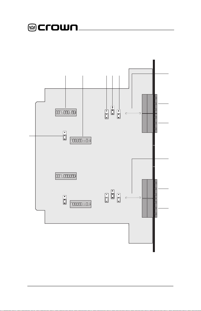
Fig. 2.1 Facilities
Page 4
Page 5

P.I.P.–BEQ
2 Facilities
A. DIP Switches
These DIP switches select the EQ
setting for the various Bose loudspeaker models with which the
P.I.P.-BEQ
can be used.
Mating solderless plugs are included for barrier block connectors.
The plugs are labelled for correct
wiring.
B. Model 802 Jumper
This jumper is used with the DIP
switches to select the model 802 response.
C. Daisy Chain Jumper
A jumper block is provided to control the signal that feeds the daisy
chain outputs. When the jumpers
are moved to EQ position, the
daisy chain outputs receive the
equalized signal. If the jumpers
are moved toward the Bypass position, the daisy chained outputs
receive the unaltered input signal.
D. Daisy Chain Ground
Lift Jumper
Remove this jumper to isolate the
daisy chain output ground from
the chassis ground. Isolation is
through an 82-ohm resistor and 0.1microfarad capacitor.
E. Output Connector
Balanced 3-pin barrier block or
XLR connectors are used for daisy
chain output to other equipment.
F. Input Connector
Balanced 3-pin barrier block or
XLR connectors are used for input
to each channel. Mating solderless plugs are also provided for
barrier block connectors. The
plugs are labelled for correct wiring.
G. Input Ground Lift
Jumper
Remove this jumper to isolate the
input ground from the chassis
ground. Isolation is provided with
an 82-ohm resistor and 0.1-microfarad capacitor.
H. Equalization Jumper
The Equalization Jumper enables
or disables the loudspeaker
equalization network for each
channel. These jumpers do NOT
affect the daisy chain ouputs.
I. Model 502B Jumper
This jumper is moved to the “SUB”
position to select the 502B
(subwoofer) response curve.
Page 5
Page 6

P.I.P.–BEQ
Switch Bank S100
Switch Number
Model 12345678910
25 & 32 Full Range ON Off Off ON ON ON Off Off ON ON
25 & 32 Bi-Amplified ON Off Off Off ON ON Off Off ON ON
8 Full Range ON Off Off ON ON ON Off ON ON Off
8 Bi-Amplified ON Off Off Off ON ON Off ON ON Off
402 Full Range Off Off Off ON ON ON ON ON ON Off
402 Bi-Amplified Off Off Off Off Off Off ON ON ON Off
502A Full Range ON Off Off ON ON ON Off Off Off Off
502A Bi-Amplified ON Off Off Off ON ON Off Off Off Off
802 Full Range Off Off ON Off ON Off ON Off ON ON
802 Bi-Amplified Off Off Off Off Off ON ON Off ON ON
502B X XXXXXXXXX
X = switch position is unimportant
Switch Bank S101
Switch Number
Model 12345678910
25 & 32 Full Range ON Off Off Off X Off Off Off ON Off
25 & 32 Bi-Amplified ON Off ON Off X Off Off Off Off Off
8 Full Range ON Off Off Off X Off Off Off ON ON
8 Bi-Amplified ON Off ON Off X Off Off ON Off ON
402 Full Range ON ON ON ON X ON Off ON Off Off
402 Bi-Amplified ON ON ON Off X ON Off Off Off Off
502A Full Range Off Off Off Off X Off Off Off ON Off
502A Bi-Amplified Off Off Off Off X Off Off Off ON Off
802 Full Range ON ON Off Off X ON ON Off ON Off
802 Bi-Amplified ON ON ON Off X ON ON Off Off Off
502B X X X XXXXXXX
X = switch position is unimportant
Page 6
Table 1—S100 and S101 Switch Positions vs Model
Page 7

P.I.P.–BEQ
Model Z100 Z103
32 Full Range FUL N
32 Bi-Amplified FUL N
8 Full Range FUL N
8 Bi-Amplified FUL N
402 Full Range FUL N
402 Bi-Amplified FUL N
502A Full Range FUL N
502A Bi-Amplified FUL N
802 Full Range FUL 802
802 Bi-Amplified FUL 802
502B SUB X
X = switch position is unimportant
Table 2—802 Response Jumper Positions vs Model
Page 7
Page 8

3 Installation
The internal jumpers and switches
of the P.I.P.-BEQ must be set prior
to installation. See the previous
section for a description of each
jumper.
20
15
10
5
dB
0
-5
-10
-15
-20
10 100 1000 10000
Fig. 3.1 Equalization Response for Model 25, 32, Full Range
The graphs in Figures 3.1 through
3.11 show the typical frequency
response for all valid switch combinations.
Frequency (Hz)
P.I.P.–BEQ
100000
20
15
10
5
dB
0
-5
-10
-15
-20
10 100 1000 10000
Frequency (Hz)
Fig. 3.2 Equalization Response for Model 25, 32, Bi-Amplified
Page 8
100000
Page 9

P.I.P.–BEQ
20
15
10
5
dB
0
-5
-10
-15
-20
10 100 1000 10000
Frequency (Hz)
Fig. 3.3 Equalization Response for Model 502A, Full Range
20
15
10
5
dB
0
-5
-10
-15
-20
10 100 1000 10000
Frequency (Hz)
100000
100000
Fig. 3.4 Equalization Response for Model 502A, Bi-Amplified
20
15
10
5
dB
0
-5
-10
-15
-20
10 100 1000 10000
100000
Frequency (Hz)
Fig. 3.5 Equalization Response for Model 802, Full Range
Page 9
Page 10

P.I.P.–BEQ
20
15
10
5
dB
0
-5
-10
-15
-20
10 100 1000 10000
Frequency (Hz)
100000
Fig. 3.6 Equalization Response for Model 802, Bi-Amplified
20
15
10
5
dB
0
-5
-10
-15
-20
10 100 1000 10000
Frequency (Hz)
100000
Fig. 3.7 Equalization Response for Model 402, Full Range
20
15
10
5
dB
0
-5
-10
-15
-20
10 100 1000 10000
Frequency (Hz)
Fig. 3.8 Equalization Response for Model 402, Bi-Amplified
Page 10
100000
Page 11

P.I.P.–BEQ
20
15
10
5
dB
0
-5
-10
-15
-20
10 100 1000 10000
Frequency (Hz)
Fig. 3.9 Equalization Response for Model 8, Full Range
20
15
10
5
dB
0
-5
-10
-15
-20
10 100 1000 10000
Frequency (Hz)
100000
100000
Fig. 3.10 Equalization Response for Model 8, Bi-Amplified
20
15
10
5
dB
0
-5
-10
-15
-20
10 100 1000 10000
100000
Frequency (Hz)
Fig. 3.11 Equalization Response for Model 502B
Page 11
Page 12

3.1 Biamping
Those who are not familiar with Bose
products may need to understand
that Bose handles the biamping of its
loudspeaker products in a different
manner than the traditional industry
practice. Standard industry practice
is to split the audio bandwidth into two
discrete sections divided by 2ndorder (12-dB/octave) or steeper filters
(see Figure 3.12).
20
15
10
5
dB
0
-5
-10
-15
-20
10 100 1000 10000
Fig. 3.12 Traditional Industry Practice for Biamping
20
15
10
5
dB
0
-5
-10
-15
-20
10 100 1000 10000
Frequency (Hz)
Fig. 3.13 Typical Bose Full-
Range Response
20
15
10
5
dB
0
-5
-10
-15
-20
10 100 1000 10000
Frequency (Hz)
Fig. 3.15 Bose 502B
Subwoofer Response
Frequency (Hz)
100000
100000
P.I.P.–BEQ
The way Bose uses the biamp designation does not limit the bandwidth
passing to the upper (high pass) section; however, it does lower the level
of bass equalization employed (see
Figures 3.13 and 3.14). The additional
bass energy required is then derived
from the 502B subwoofer( see Figures 3.25 and 3.16).
100000
20
15
10
5
dB
0
-5
-10
-15
-20
10 100 1000 10000
Frequency (Hz)
100000
Fig. 3.14 Typical Bose
Biamplified Response
20
15
10
5
dB
0
-5
-10
-15
-20
10 100 1000 10000
Frequency (Hz)
100000
Fig. 3.16 Typical Bose
Response Using 502B for Bass
Supplement
Page 12
Page 13

P.I.P.–BEQ
3.2 Installation Procedures
You may need a phillips screwdriver
to remove the existing
or panel from your amplifier.
CAUTION: Before connecting this
or any
P.I.P.
to your amplifier, it is
important to turn its level controls
down, turn it off and remove the AC
power. Don’t touch the circuitry.
Even though the amplifier is off,
there could still be enough energy
remaining to cause electric shock.
1. Turn down the level controls (full
counterclockwise), turn off the
amplifier and unplug it from the
AC power source.
2. Remove the existing
ule or panel (two screws). For
PIP2
amplifiers, this may involve
disconnecting the
PIP2
input adapter (see Figures
3.18 and 3.19). If a
adapter is already present, do not
remove the ribbon cables from
the adapter. Otherwise you will
have to reconnect them in the
next step.
Standard P.I.P. Amplifiers
3.
the edges of the
P.I.P.
card rails and firmly push
P.I.P.
P.I.P.
P.I.P.
PIP2
P.I.P.–BEQ
BACK PANEL
OF AMPLIFIER
module
mod-
from a
input
: Align
in the
P.I.P.
MODULE
the unit in until it is seated against
the mounting bracket (see Figure
3.17).
PIP2 Amplifiers:
(Requires a
PIP2
input adaptor. Crown part number Q43528-1.) Connect the
PIP2
input adapter to the two input
cables of the amplifier (see Figure
3.18). Notice that the
PIP2
input
adapter should be positioned
with the
P.I.P.
edge connector on
top and facing away from the amplifier. The 20 pin cable (A) is connected first then the 18 pin cable
(B) is connected. Both ribbon
cables should extend below the
PIP2
input adapter.
FROM AMPLIFIER
Q43528-1
B
A
A
18 PIN (B)
B
20 PIN (A)
Fig. 3.18 PIP2 Input Adapter
Connection
Next, insert the edge connector of
the
P.I.P.–BEQ
adapter (see Figure 3.19) and in-
into the
BACK PANEL
OF PIP2
AMPLIFIER
PIP2 CONNECTOR
BOARD
PIP2
MODULE
input
P.I.P.
Fig. 3.17 Installation into a
Standard P.I.P. Amplifier
Fig. 3.19 Installation into a
PIP2 Amplifier
Page 13
Page 14

P.I.P.–BEQ
sert the assembly into the
opening in the back of the amplifier.
4. Tighten the two
thumbscrews.
5. Connect input and output wiring.
6. Plug in the amplifier and turn it on.
Adjust its level controls to a desired setting. (In Dual mode, the
level controls can now be used to
balance the low and high frequencies.)
P.I.P.
P.I.P.
mounting
Do not tamper with the circuitry.
Circuit changes made by unauthorized personnel, or unauthorized
circuit modifications are not allowed.
Remember: Crown is not liable for
any damage resulting from over-
BALANCED
SOURCE
driving other components in your
sound system.
Figure 3.20 shows how to wire a
balanced and unbalanced source
or daisy-chain output to the barrier
block connectors.
Important: If the amplifier is used
in either Bridged-Mono or ParallelMono mode, you must turn the Ch.
2 amplifier level control off (fully
counterclockwise). The input and
level control of Ch. 2 are not defeated in mono mode so any signal
applied to Ch. 2 will beat against
the signal in Ch. 1.
Refer to the amplifier
Manual
for more information about
Reference
Bridged-Mono or Parallel-Mono
modes of operation.
UNBALANCED
SOURCE
Page 14
– + – +
Fig. 3.20 Audio Wiring
Page 15

P.I.P.–BEQ
4 Specifications
Note: All specifications are referenced to a 0.775-V input signal.
Signal to Noise: Greater than 90
dB from 20 Hz to 20 kHz in Bypass
mode. Greater than 85 dB in EQ
mode.
Frequency Response:
from 20 Hz to 20 kHz in Bypass
mode. ±2 dB from the response
curves in Figure 3.1 through 3.6 in
EQ mode.
Harmonic Distortion (THD): Less
than 0.05% THD from 20 Hz to 20
kHz in Bypass mode with a 0 dBu
input signal. Less than 0.1% THD
from 20 Hz to 20 kHz in EQ mode
at 0 dBu.
Common Mode Rejection: Better
than 60 dB up to 1 kHz.
Crosstalk: Less than –60 dB from
20 Hz to 20 kHz.
±0.1 dB
Connectors: Solderless barrier
block or XLR connectors (depending on model) for both input and
daisy chain output.
Input Impedance:
Nominally 50
kohms balanced; 25 kohms unbalanced.
Maximum Input Level:
Output Impedance:
+20 dB.
(daisy chain
output) Nominally 75 ohms balanced.
Maximum Output Level:
(daisy
chain output) +20 dB into a 600ohm load.
Nominal Gain:
Dimensions:
–6 dBV at 1 kHz
3
6
⁄8 x 17⁄8 x 37⁄8 in.
(16.2 x 4.8 x 9.8 cm).
Notes:
1. All resistor values are in ohms, ¼ W, 5% unless otherwise specified.
2. All capacitor values are in microfarads unless otherwise specified.
3. P1 pins 6, 8, 9, 10, 12-22 are not used.
Page 15
Page 16

P.I.P.–BEQ
For Technical Support contact:
Crown Audio Division Technical Support Group
Plant 2 SW, 1718 W. Mishawaka Rd., Elkhart, Indiana 46517 U.S.A.
Phone: 800-342-6939 (North America, Puerto Rico and Virgin Islands) or 219-294-8200
Fax: 219-294-8301 Fax Back (North America only): 800-294-4094 or 219-293-9200
Fax Back (International): 219-294-8100
Internet: http://www.crownintl.com
Page 16
 Loading...