

Crown PIPATNJ Owners manual

+ +
∞∞
©
2002 by Crown Audio, Inc., P.O. Box 1000, Elkhart, IN 46515-1000 U.S.A.
Telephone: 574-294-8000. Fax: 574-294-8329. Trademark Notice: PIP is a
trademark and Crown , Com-Tech, Macro-Tech and P.I.P. are registered
trademarks of Crown International. Other trademarks are the property of
their respective owners.
127848-3
3/02
+ +
∞∞
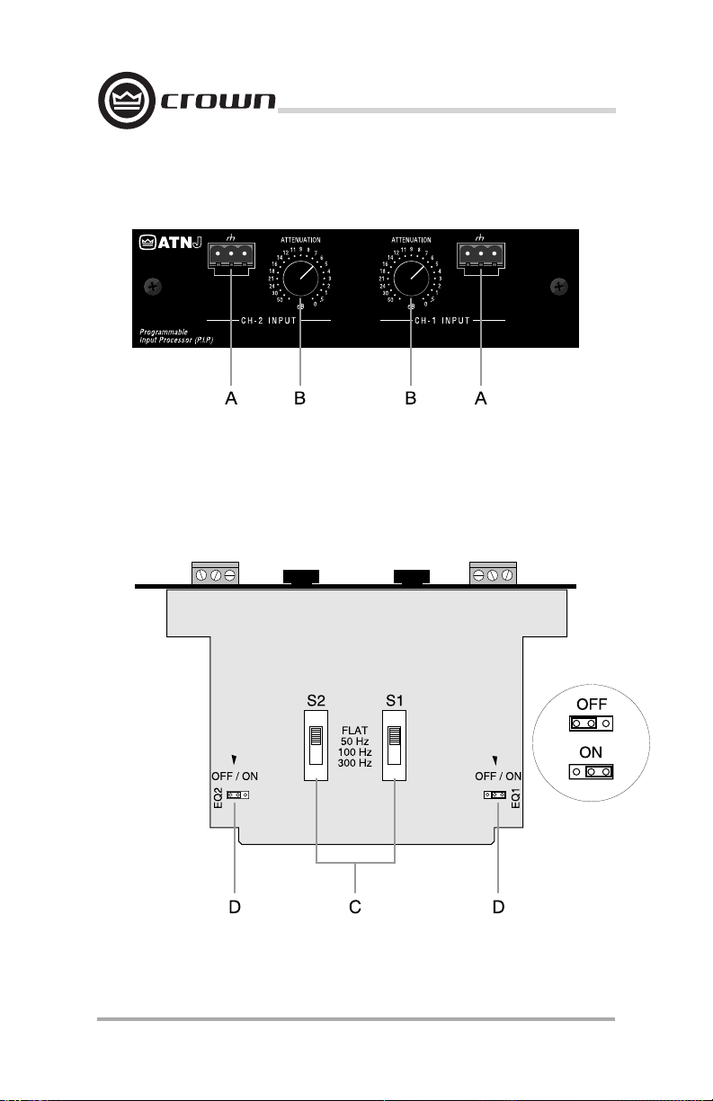
Fig. 1.1 Front View
P.I.P.–ATNJ
Page 2
Fig. 1.2 Bottom View
Reference Manual

P.I.P.–ATNJ
1 Welcome
Thank you for purchasing the Crown
®
P.I.P.
–ATNJ accessory.
grammable Input Processor) modules are designed to quickly install in
the rear panel of Crown
Macro-Tech
®
or Studio Reference series amplifiers. Their versatile features
expand the capabilities of your amplifier and enable you to customize it for
your particular needs.
You should find these items when you
unpack:
P.I.P.–ATNJ Module
Two 8-32 Phillips Machine Screws
Two Lock Washers
Two Quick-Disconnect Barrier
Blocks
This Reference Manual
Features
❏ Balanced inputs with 1:1 isolation
transformers to minimize input noise.
❏ RFI filter for attenuation of unwanted
ultrasonic frequencies. The RFI filter
is a 12 dB/octave, Bessel-tuned lowpass filter with a 3 dB roll-off point at
33 kHz.
❏ Switchable subsonic/bass filter with
the following settings: flat, 50, 100,
or 300 Hz roll-off.
❏ Switchable constant-directivity horn
equalization network.
❏ Calibrated 21 position attenuators
give accurate level control of the input signal.
❏ Removable barrier block connectors
provide greater wiring flexibility and
easy installation.
™
PIP
(Pro-
Com-Tech
Facilities
A. Balanced Input
These removable barrier-block connectors (Figure 1.1) make it quick and
easy to attach an input cable with just
®
three screws. Once the cable is at-
,
tached, the connector can be quickly
unplugged and, if desired, moved to
a different amplifier.
B. Input Attenuators
Each channel has a calibrated attenuator (Figure 1.1) for accurate
level adjustment. They have 21
detented positions which “click” into
place for ease of use.
C. Subsonic/Bass Switch
A 4-position slide switch for each
channel (Figure 1.2) controls the subsonic/bass filter. This filter is an 18 dB/
octave Butterworth high-pass filter
which can be selected to attenuate
frequencies below 50 Hz, 100 Hz or
300 Hz. It can also be switched off
(FLAT). The switch positions are labelled on the circuit board between
the two switches.
D. Horn Equalization Jumper
A jumper is provided for each channel (Figure 1.2) to enable/disable the
constant-directivity horn equalization.
The jumper for channel 1 (EQ1) is
shown in the ON position while the
channel 2 jumper (EQ2) is shown in
the OFF position. This equalization
circuit is a 6 dB/octave shelving network with a 3 dB rise at 3.2 kHz and
a peak boost of 12.5 dB at 24 kHz.
Reference Manual
Page 3
 Loading...