

Crown PH-4B User Manual
PH-4B
POWER
PHANTOM
IN
MIC 1
OUT
IN
MIC 2
OUT
IN
MIC 3
OUT
IN
MIC 4
OUT
AUDIO
OUT
MIC MICMICMIC
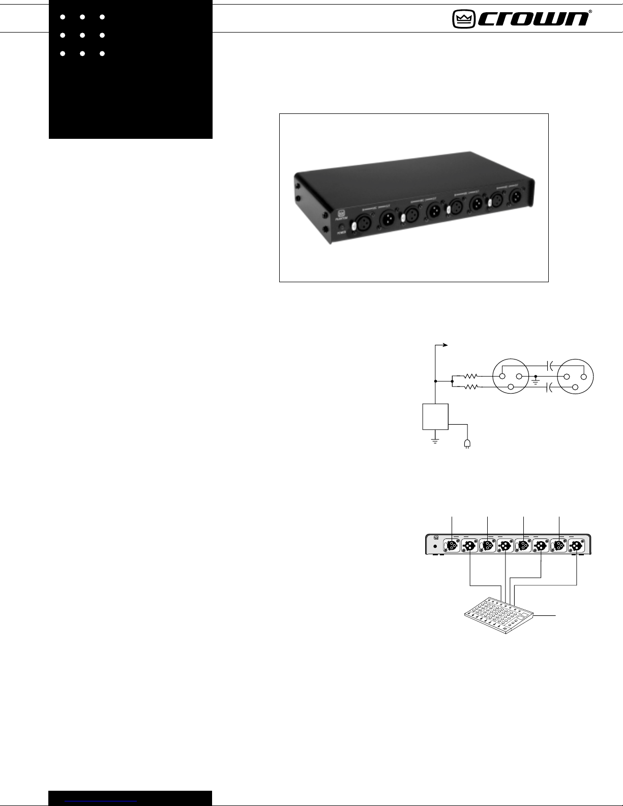
he Crown PH-4B is a 48-volt phantom power supply for condenser and
electret-condenser microphones. It
T
has four channels for powering up to four
microphones.
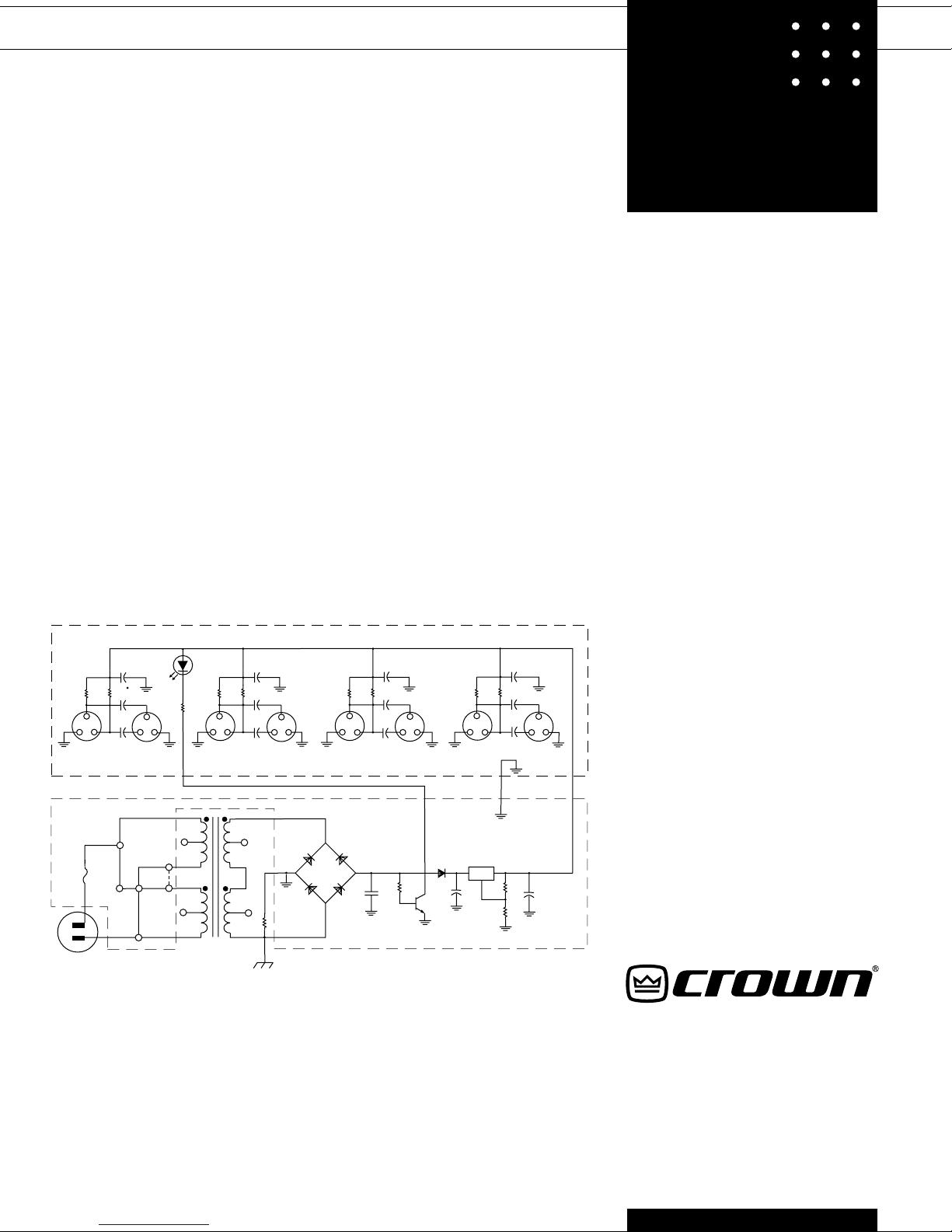
As shown in Fig. 1, it supplies 48V DC on
mic-connector pins 2 and 3 with respect to
pin 1 (complies with DIN standard 45 596).
The phantom supply is highly filtered to
minimize hum.
The PH-4B itself is powered by 120V AC. It
is also available powered by 220V and 240V
as the PH-4BE4.
Operation
1. Plug the AC cord into a wall outlet. The
LED pilot light will show that the line voltage
is applied.
2. Please refer to Fig. 2. You will connect the
PH-4B between your mic and your system
mic input.
3. Plug the cable from your microphoneinto
one of the mic inputs on the PH-4B.
4. Obtain another mic cable and plug it into
the adjacent output on the PH-4B.
5. Plug the other end of that cable into the
mic input on your mixer or recorder.
The total current drain of all channels of the
PH-4B should not exceed 100 mA. To determine how much current your microphones
draw, check their data sheets and look for
the current-drain specification.
CAUTION: Inside the mic-cable male XLR
connector (the one that plugs into a PH-4B
input), do NOT tie pin 1 to the shell ground
lug. If pin 1 is tied to the shell and you connect an output of the PH-4B into an unbalanced mic input, this connection might
cause hum.
FOUR CHANNEL
AC POWERED 48V
PHANTOM POWER SUPPL Y
Specifications
Type: Four-channel, AC powered.
Supply voltage: +48V DC on pins 2 and 3 with
respect to pin 1 of microphone input connector.
Total output current: 100 mA continuous.
Line voltage (PH-4B): 120 VAC.
Line voltage (PH-4BE4): 220 - 240 VAC.
Connectors: 3-pin pro audio (XLR-type) input
and output connectors.
Construction: Steel for strength and magnetic
shielding.
Dimensions: 7 1/16" L x 12" W x 1 3/4" H
(17.93cm x 30.48cm x 4.45cm).
Finish: Black.
Weight: 4 lb. 12 oz. (2.15 kg).
Accessory: RMPB kit.
Fig. 1
48 VDC
SUPPLY
Fig. 2
TO OTHER
CHANNELS
6.8k
6.8k
MIC IN
3-PIN
FEMALE
2
3
MIC OUT
3-PIN
MALE
33µF
50V
+
1
+
33µF
50V
1
2
3
Hum might also occur if the PH-4B is rackmounted and connected to an unbalanced
mic input. If this happens, electrically isolate
the PH-4B from the rack (say, by using nylon bolts and washers).
How to Prevent Switching Clicks
In rare instances, you may need to use the
PH-4B with a mic-level switcher. This may
result in switching clicks as each PH-4B output connector is fed by two large coupling
capacitors. These capacitors block the DC
voltage from the phantom power.
Since these capacitors are charged by phantom voltage, some DC appears at the PH-4B
outputs. This DC goes away when the PH-4B
is plugged into a mixer microphone input
because the mixer input impedance drains
off the charge.
However, if you feed the PH-4B outputs to a
mic-level switcher, you will hear clicks or
pops when the outputs are switched, due to
the capacitor charge.
To prevent these clicks: In the switcher, sol-
der a 47K, 1/8 watt resistor between input
pins 1 and 2, and another 47K resistor between input pins 1 and 3. Do this for each
PH-4B output connector. Those bleeder resistors will drain off the capacitor charge.
Architects’ and Engineers’ Specifications
The unit shall be the Crown PH-4B phantom
power supply or equivalent. It shall supply
48V DC on pins 2 and 3 with respect to pin 1
of the mic input connector, according to DIN
standard 45 596. It shall provide four channels for powering up to four condenser or
electret condenser microphones. The PH-4B
shall be powered by 120V AC. The PH-4BE4
shall be powered by 220V or 240V AC. The
Crown PH-4B is specified.
Warranty
The PH-4B has a three-year warranty.
PH-4B
Service
If the PH-4B does not function properly,
verify that you measure approximately 48V
DC on pins 2 and 3 with respect to pin 1 in
each mic input connector (the female connector in each channel). Also repair or replace any defective cables. If the PH-4B
requires service, return it in the original
packaging to: Crown Service Department,
Plant 2 SW, 1718 West Mishawaka Road,
Elkhart, IN 46517. For further assistance or
technical support call (800) 342-6939.
J9
6.81K
1%
1
120VAC
+
_
10%
INPUT MODULE
+
330
50V
+
33
50V
+
33
50V
2
JUMPER
120V
POWER
3
J2
JUMPER
240V
JUMPER
120V
AMBER
1
680
6.81K
1%
3
2
J1
1/8 A
WHT
WHT
4.7K
1W
ORG
BRN
BLK
BRN
680
LED1
6.81K
BLK
+
330
6.81K
50V
1%
1%
+
33
50V
3
1
2
J3
RED
RED/YEL
YEL
RED
RED/YEL
YEL
T1
3
2
1
+
J4
33
50V
D4
D5
2.7
.5W
680
+
330
6.81K
6.81K
50V
1%
1%
+
33
50V
3
12
+
J5
33
50V
POWER SUPPLY MODULE
D3
.047
D2
3
2
1
J6
D1
27 OK
Q1
6.81K
1%
1
IU1O
+
220
160V
680
+
330
6.81K
50V
1%
+
33
50V
3
2
J7
BLK
2.87K
1% 1W
3
2
1
+
J8
33
50V
RED
+
75
1%
4.7
63V
PH-4B Schematic
Crown International, Inc.
P.O. Box 1000
Elkhart, IN 46515-1000
TEL: 219-294-8000
©
Specifications subject to change without prior notice.
Crown
tional, Inc.
FAX: 219-294-8FAX
2000 Crown International, Inc.
®
is a registered trademark of Crown Interna-
02/00 125519-2
 Loading...