

Page 1

Page 2

Page 3

Table of Contents
I. Product Description 2
II. Specifi cations 4
III. Before Installing 5
IV. Locating The Boiler 5
V. Mounting The Boiler 7
VI. Air For Ventilation 10
VII. Venting 12
A. Vent System Design 12
B. Removing An Existing Boiler From Common Chimney 19
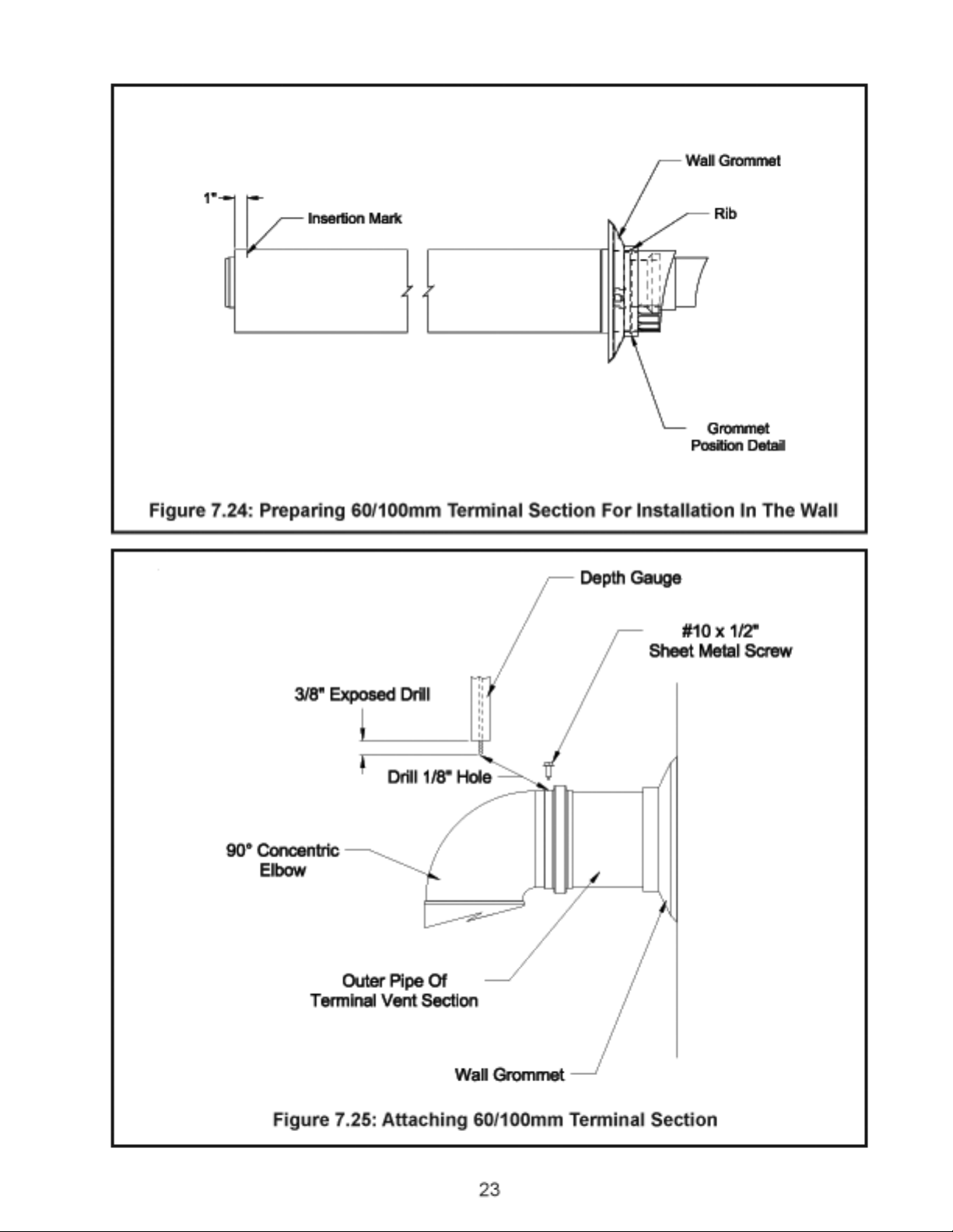
C. Assembly of Crown 60/100 Concentric Venting 20
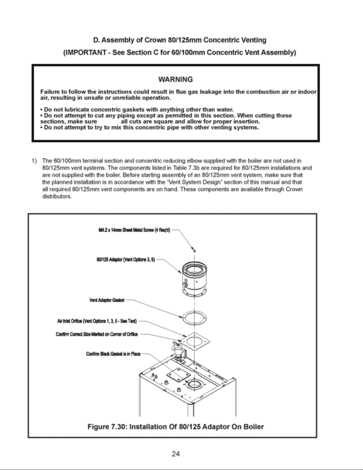
D. Assembly of Crown 80/125 Concentric Venting 24
E. Condensate Trap and Drain Line 33
VIII. Gas Piping 34
IX. System Piping 36
X. Domestic Water Piping 43
XI. Wiring 46
XII. Start-up and Checkout 51
XIII. Operation 58
XIV. Service and Maintenance 62
XV. Troubleshooting 66
XVI. Parts 69
Appendix A Special Requirements For Side-Wall 84
Vented Appliances In The Commonwealth
of Massachusetts
1
Page 4
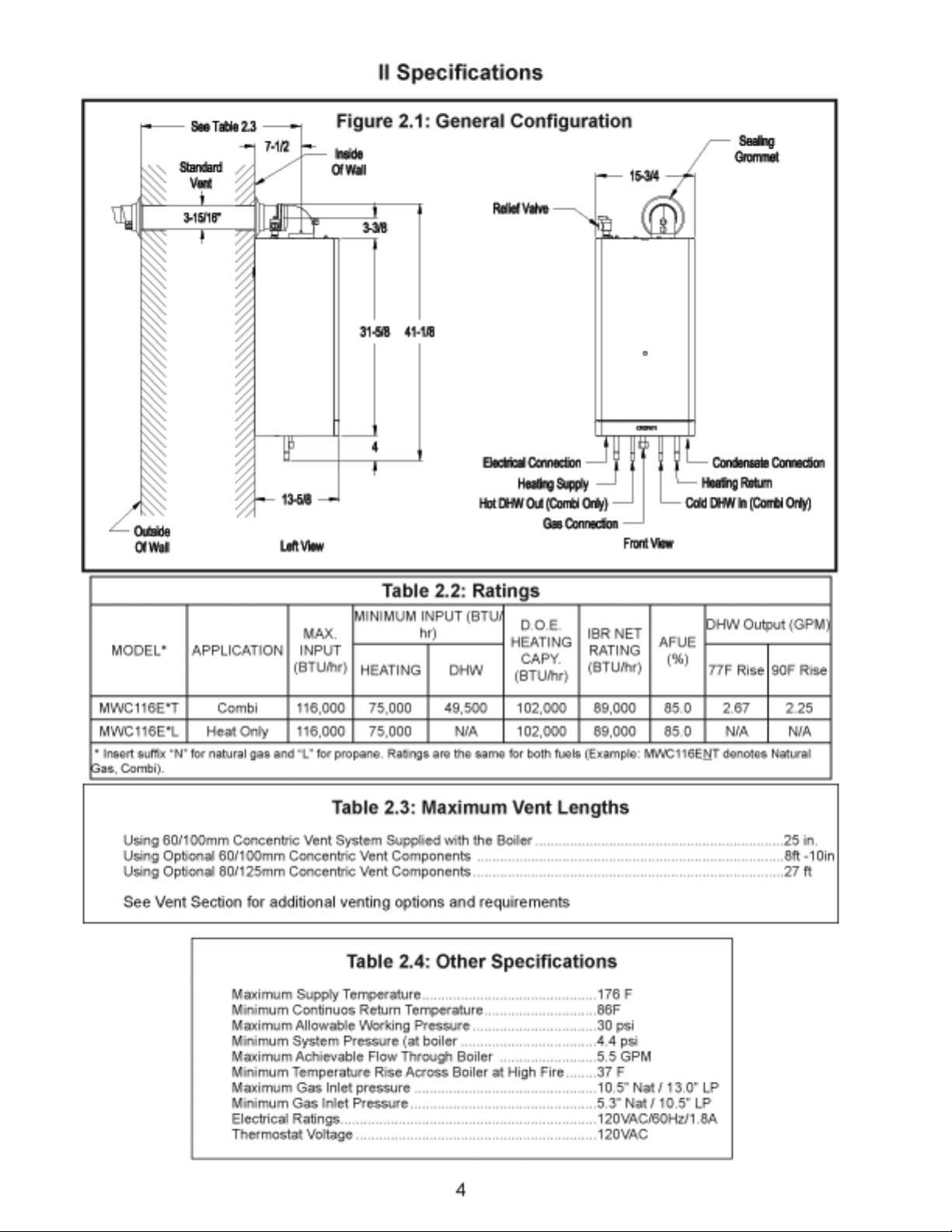
I Product Description
The MWC Series are gas fi red condensing boilers designed for use in forced hot water heating systems
requiring supply water temperatures of 176F or less and return water temperatures greater than 86F. The
primary heat exchanger is a copper water tube design. Additional heat is extracted from the fl ue gas in a
stainless steel secondary heat exchanger located down stream of the inducer. These boilers include a built in
circulator, expansion tank, and automatic air vent. In addition, “combi” models include a plate exchanger for
domestic hot water (DHW) generation. All MWC Series boilers are designed for installation on a wall and may
be vented vertically or horizontally with combustion air supplied from outdoors.
Key Component
1 Primary Heat Exchanger
2 Secondary Heat Exchanger
3 Inducer
4 Burner
5 Electrodes and Flame Rod
6 Circulator
7 Automatic Air Vent
8 Condensate Trap
9 Control Box
10 Differential Boiler Water Pressure Switch
11 Ignition module/Gas Valve
12 Air Pressure Switch
13 Flue Gas Temperature Limit
14 Supply Temperature Limit
* Expansion Tank
* Plate Heat Exchanger (Combi Only)
* 3-Way Diverting Valve (Combi Only)
* Supply Temperature Sensor
* DHW Temperature Sensor (Combi Only)
* DHW Flow Switch (Combi Only)
* Not visible
2
Page 5
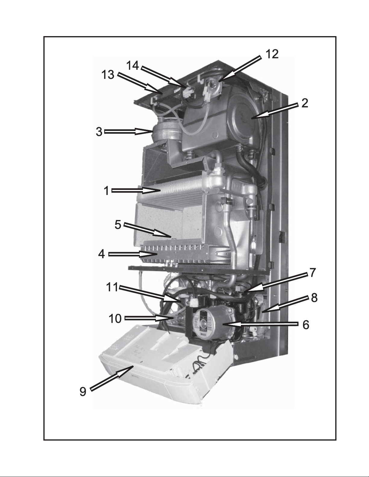
Figure 1.1: MWC Boiler Principle Components
3
Page 6
Page 7

III Before Installing
Safe, reliable operation of this boiler depends upon installation by a professional heating contractor in 1)
strict accordance with this manual and the authority having jurisdiction.
In the absence of an authority having jurisdiction, installation must be in accordance with this manual •
and the National Fuel Gas Code, ANSI Z223.1.
Natural Gas and Propane Installation Code.
Where required by the authority having jurisdiction, this installation must conform to the • Standard for
Controls and Safety Devices for Automatically Fired Boilers (ANSI/ASME CSD-1).
Read Section VII to verify that the maximum combustion air and exhaust pipe lengths will not be 2)
exceeded in the planned installation. Also verify that the vent terminal can be located in accordance with
Section VII.
Make sure that the boiler is correctly sized:3)
For heating systems employing convection radiation (baseboard or radiators), use an industry a)
accepted sizing method such as the I=B=R Heat Loss Calculation Guide (Pub. #H21 or #H22)
published by the Hydronics Institute in Berkeley Heights, NJ.
In sizing the boiler take into consideration the following boiler water fl ow/temperature limitations:b)
Maximum regulated supply temperature is 176F•
Maximum fl ow through the boiler is approximately 5.5GPM. •
Minimum boiler temperature rise is approximately 37F at high fi re. •
For new radiant heating systems, refer to the radiant tubing manufacturer’s boiler sizing guidelines. c)
For combi boilers make sure that the domestic hot water fl ow rate shown in Table 2.2, will be d)
adequate to meet the peak demand for domestic hot water.
/NFPA 54 and/or CAN/CSA B 149.1
Make sure that the boiler received is confi gured for the correct gas (natural or LP).5)
Make sure that the boiler is confi gured for use at the altitude at which it is to be installed. 6)
NOTICE
This product must be installed by a licensed plumber or gas fi tter when installed within the
Commonwealth of Massachusetts. See Appendix A for additional important information about
installing this product within the Commonwealth of Massachusetts.
IV Locating the Boiler
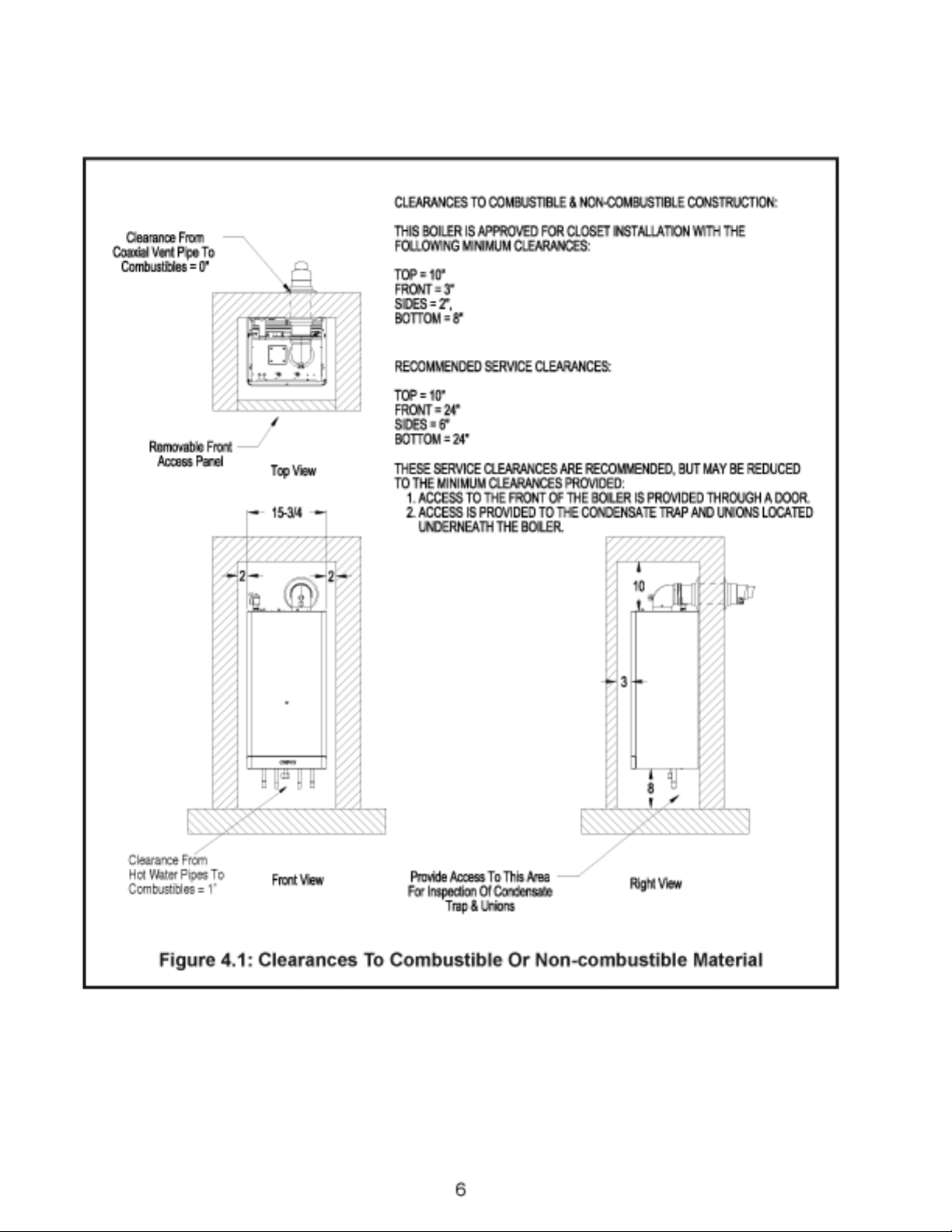
Observe the minimum clearances shown in Figure 4.1. These clearances apply to both combustible and 1)
non-combustible materials.
Note the recommended service clearances in Figure 4.1. These service clearances are recommended, 2)
but may reduced to the combustible clearances provided:
Access to the front of the boiler is provided through a door•
Access is provided to the condensate trap located underneath the boiler.•
The relief valve must be installed in the factory specifi ed location.3)
The boiler should be located so as to minimize the length of the vent system.4)
The boiler must not be installed on carpeting.5)
The combustion air piping must terminate where outdoor air is available for combustion and away from 6)
areas that will contaminate combustion air. Avoid areas near chemical products containing chlorine,
chloride based salts, chloro/fl uorocarbons, paint removers, cleaning solvents and detergents.
5
Page 8
Page 9

V Mounting The Boiler
CAUTION
This boiler weighs approximately 110 pounds:
Two people are required to safely lift this boiler onto the wall mounting hook.•
Make sure that wall mounting hook is anchored to a structure capable of supporting the •
weight of the boiler and attached piping when fi lled with water.
Jurisdictions in areas subject to earthquakes may have special requirements for supporting
this boiler. These local requirements take precedence over the requirements shown below.
Mounting Steps:
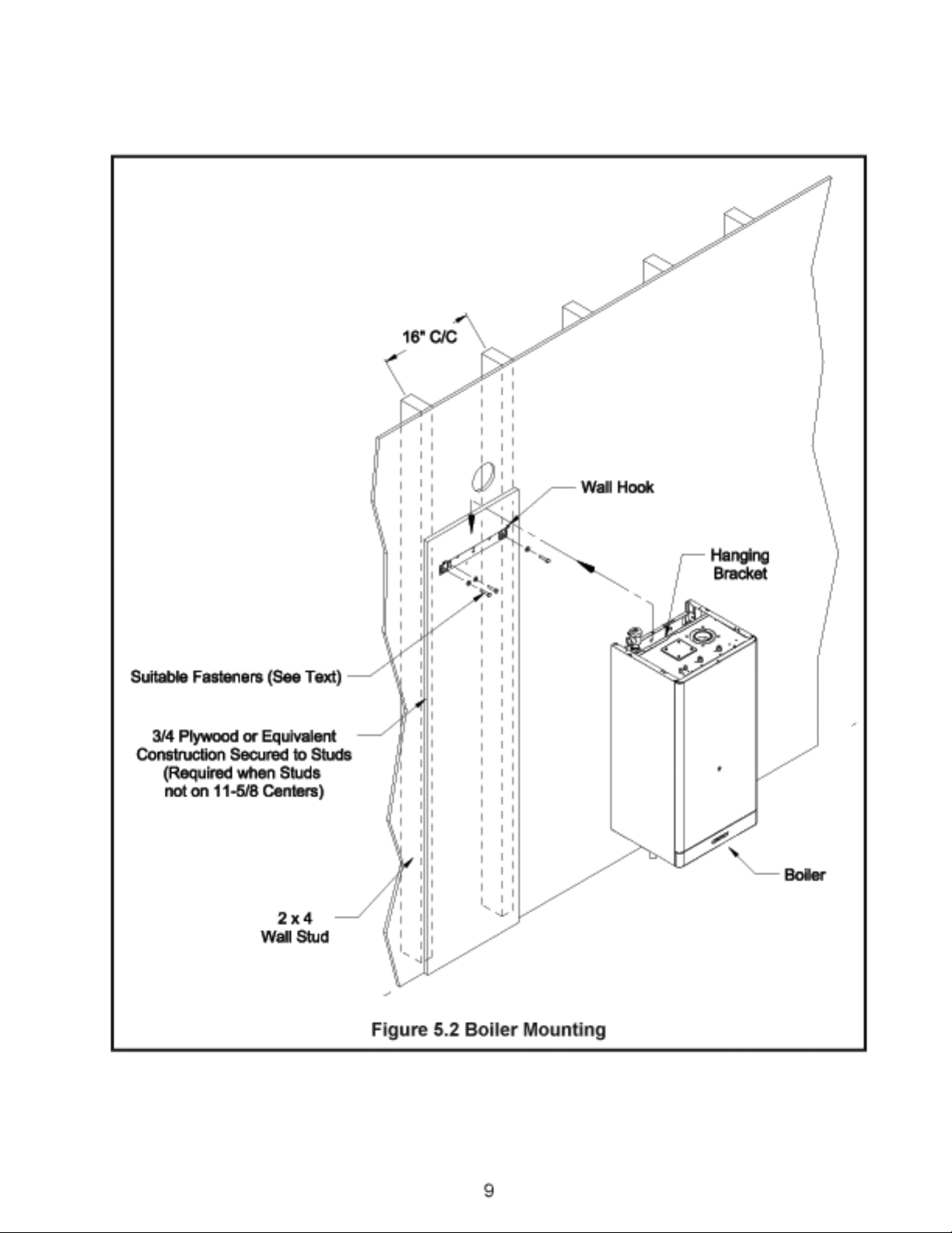
If the boiler is installed on a framed wall, minimum acceptable framing are 2 x 4 studs. The boiler 1)
mounting holes are on 11-5/8” centers. Usually the wall studs will be on 16” centers. In such cases, both
boiler bracket mounting holes must be anchored to ¾” Plywood, horizontal 2 x 4s anchored to the studs,
or some other framing system capable of supporting the boiler. Attachment of either bracket hole to
wallboard alone is unacceptable.
When mounting this boiler directly onto studs covered with 1/2” wall board, 5/16 x 2” lag screws are 2)
recommended. When the boiler is attached to other types of construction, such as masonry, use fasteners
capable of supporting the weight of the boiler and attached piping in accordance with good construction
practice and applicable local codes.
Make sure that the surface to which the boiler is mounted is plumb.3)
Before mounting the boiler, make sure that wall selected does not have any framing or other construction 4)
that will interfere with the vent pipe penetration.
Tape the paper template to the wall in the chosen location. Be sure to level the template.5)
Pre-drill two holes in the center of the “oval” slots on the mounting bracket sized for the hardware being 6)
used.
Mount the bracket to the wall. Be sure to level the bracket by adjusting the screw in the vertical slot.7)
Pre-drill the remaining hole in the mounting bracket and secure the fi nal screw .8)
Cut the opening in the wall for the vent system. The recommended hole diameter for the standard 9)
60/100mm venting is 4-3/8”.
Hang the boiler on the wall bracket as shown in Figure 5.2.10)
Verify that the front and sides of the boiler are plumb.11)
See Section VII (“Venting) for instructions on attaching the vent system to the boiler. 12)
A hot water boiler installed above radiation level or as the Authority having jurisdiction,
13)
must be provided with a low water cutoff device either as a part of the boiler or at the time of installation.
7
Page 10
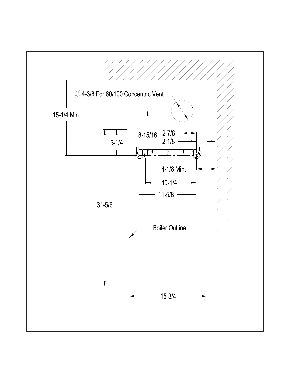
Figure 5.1 Wall Mounting Hole Locations
8
Page 11
Page 12

VI Air for Ventilation
WARNING
Outdoor combustion air must be piped to the air intake. Never pipe combustion air from areas containing
contaminates such as areas where swimming pool chemicals are stored. Contaminated combustion
air will damage the boiler and may cause property damage, personal injury or loss of life.
Air for combustion and ventilation, of the National Flue Gas Code, ANSI Z223.1/NFPA 54 CAN/CSA B 149.1
Natural Gas and Propane Installation Code, or applicable provisions of the local building codes.
Air for combustion must always be obtained directly from outdoors, however suffi cient air for ventilation must
still be provided in the boiler room. Air for ventilation is required to keep various boiler components from
overheating and is always obtained from indoors. To ensure an adequate ventilation air supply, perform the
following steps:
Step 1: Determine whether the boiler is to be installed in a confi ned space - A confi ned space is defi ned by
the
as having a volume less than 50 cubic feet per 1000 BTU/hr input of all appliances
installed in that space. To determine whether the boiler room is a confi ned space:
Total the input of all appliances in the boiler room in thousands of BTU/hr. Round the result to the next A.
highest 1000 BTU/hr.
,ANSI Z223.1.
/NFPA 54 and/or CAN/CSA B 149.1National Fuel Gas Code
Natural Gas and Propane Installation Code.
Find the volume of the room in cubic feet. The volume of the room in cubic feet is:B.
Length (ft) x width (ft) x ceiling height (ft)
In calculating the volume of the boiler room, consider the volume of adjoining spaces only if no doors
are installed between them. If doors are installed between the boiler room and an adjoining space, do
not consider the volume of the adjoining space, even if the door is normally left open.
Divide the volume of the boiler room by the input in thousands of BTU/hr. If the result is less than 50, the C.
boiler room is a confi ned space.
Example:
A MWC116 and a water heater are to be installed in a room measuring 6ft – 3 in x 7ft with an 8 ft ceiling. The
water heater has an input of 30000 BTU/hr:
Total input in thousands of BTU/hr = (116000 BTU/hr + 30000 BTU/hr) / 1000 = 146 MBTU/hr
Volume of room = 6.25 ft x 7 ft x 8 ft = 350 ft
350/146 = 2.40. Since 2.33 is less than 50, the boiler room is a confi ned space.
Step 2a: If the boiler is to be placed in a confi ned space, provide two openings into the boiler room, one near
the fl oor and one near the ceiling. The top edge of the upper opening must be within 12” of the ceiling and the
bottom edge of the lower opening must be within 12” of the fl oor (Fig 6.1). The minimum opening dimension is
3 inches.
3
If the MWC boiler is the only gas-burning appliance in the boiler room, these openings must each •
have a minimum free area of 54 square inches.
If other gas-burning appliances are in the boiler room, size the openings in accordance with the •
appliance manufacturer’s instructions or the National Fuel Gas Code
/NFPA 54 and/or CAN/CSA B 149.1.
54 square inches even if opening requirements for other appliances are less.
Minimum opening free area is
ANSI Z223.1.
10
Page 13
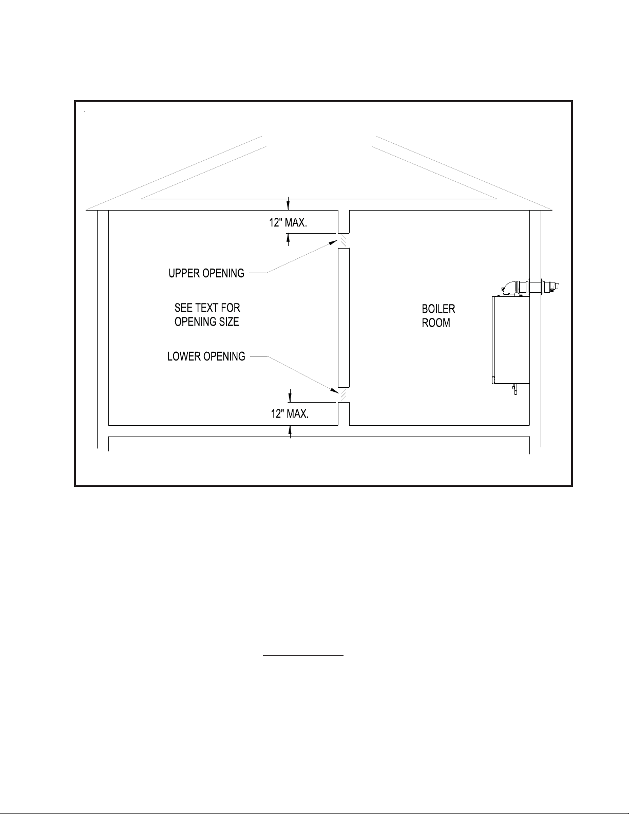
Figure 6.1: Boiler Installed In A Confi ned Space, Ventilation Air From Inside
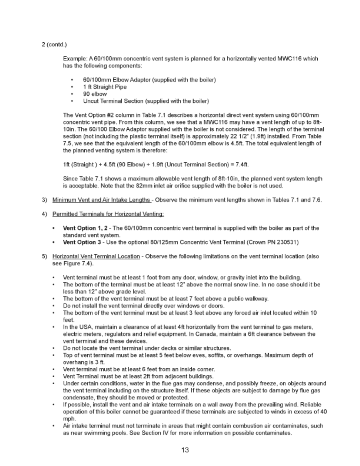
Step 2a (contd.)
If the total volume of both the boiler room and the room to which the openings connect is less than •
50 cubic feet per 1000 BTU/hr of total appliance input, install a pair of identical openings into a third
room. Connect additional rooms with openings until the total volume of all rooms is at least 50 cubic
feet per 1000 BTU/hr of input.
The “free area” of an opening takes into account the blocking effect of mesh, grills, and louvers. •
Where screens are used, they must be no fi ner than ¼” (4 x 4) mesh.
Step 2b: If the boiler is to be placed in an unconfi ned space the natural infi ltration into the boiler room will
provide adequate air for ventilation without additional openings into boiler room.
11
Page 14
Page 15
Page 16
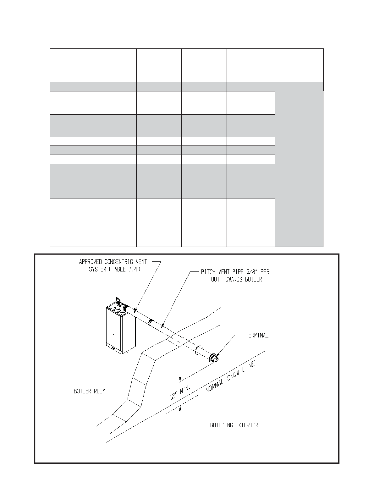
Table 7.1: Summary Of Horizontal Venting Options
VENT OPTION # 1 2 3 4
CLASSIFICATION USED IN THIS
MANUAL
ILLUSTRATED IN FIGURE 7.2 7.2 7.2
HORIZONTAL
CONCENTRIC
HORIZONTAL
CONCENTRIC
HORIZONTAL
CONCENTRIC
RESERVED
FOR FUTURE
USE
VENT PIPE PENETRATION
THROUGH STRUCTURE
VENT PIPE SIZE
INLET AIR ORIFICE SIZE
MAX. VENT LENGTH
MIN. VENT LENGTH
VENT TERMINAL
VENT MATERIAL
WALL WALL WALL
60/100 mm
CONCENTRIC
82mm
25in
6in
CROWN
#230520
(INCLUDED
WITH BOILER)
CROWN
60/100mm
VENT
COMPO-
NENTS
SHOWN IN
TABLE 7.3a
60/100 mm
CONCENTRIC
Not Used 82mm
8ft - 10in 27ft - 10in
26in 6in
CROWN
#230520
(INCLUDED
WITH BOILER)
CROWN
60/100mm
VENT
COMPO-
NENTS
SHOWN IN
TABLE 7.3a
80/125 mm
CONCENTRIC
CROWN
#230531
CROWN
80/125mm VENT
COMPONENTS
SHOWN IN
TABLE 7.3b
Figure 7.2: Horizontal Concentric Venting (Vent Options 1-3)
14
Page 17
Page 18
Page 19
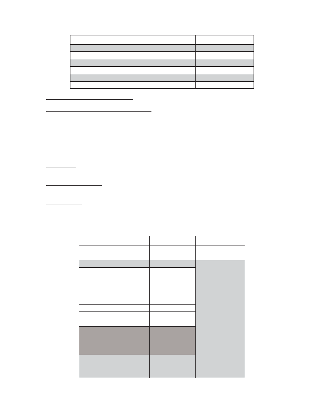
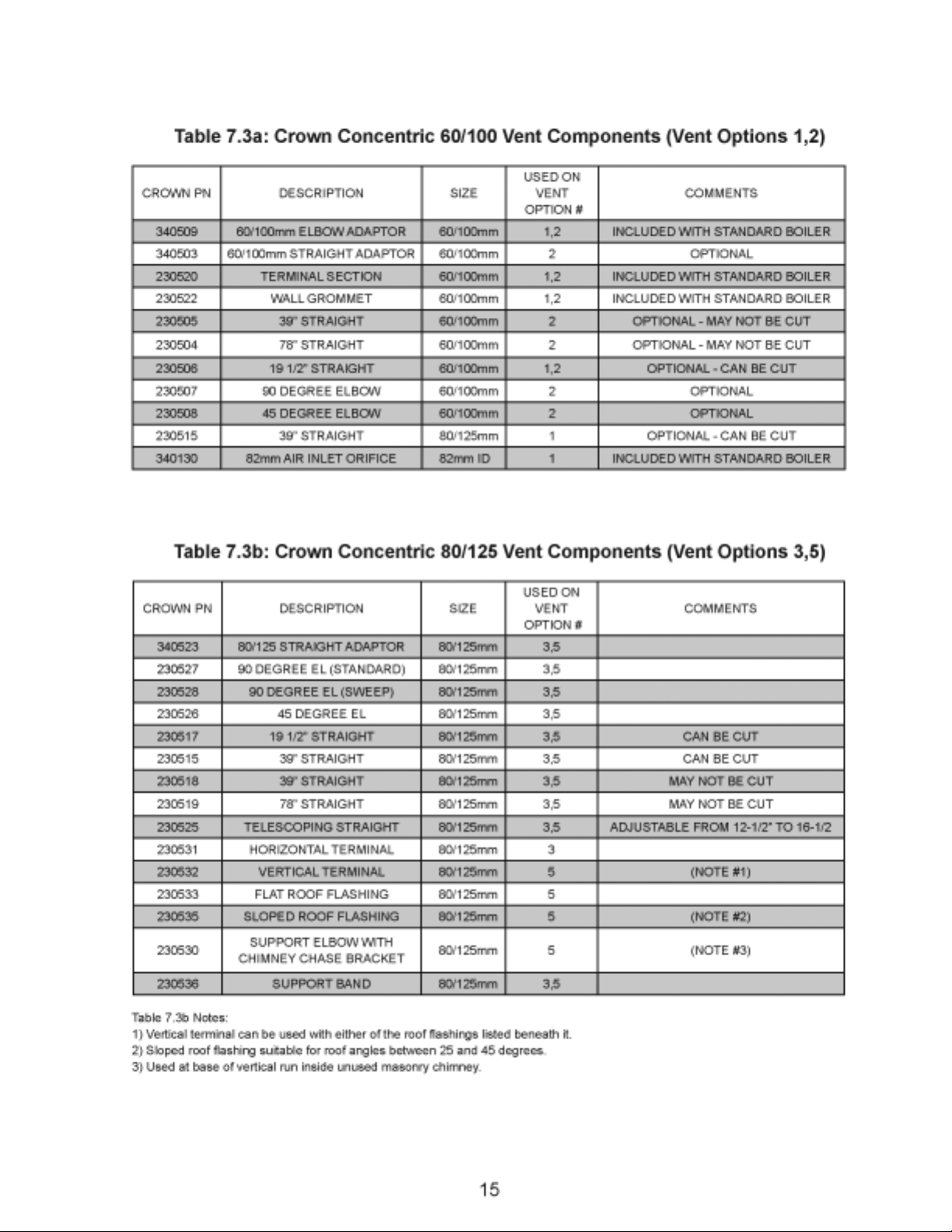
Table 7.5: Vent/ Air Intake Fitting Equivalent Length
VENT FITTING EQUIVALENT LENGTH (ft)
60/100mm 90° CONCENTRIC ELBOW 4.5
60/100mm 45° CONCENTRIC ELBOW 4.0
80/125mm 90° CONCENTRIC ELBOW 8.5
80/125mm 90° SWEEP CONCENTRIC ELBOW 5.5
80/125mm 45° CONCENTRIC ELBOW 3.0
80/125mm 90° CONCENTRIC SUPPORT ELBOW 8.5
Permitted Terminals for Vertical Venting6) - Use Crown PN 230532 with the appropriate flashing (Table 7.3b)
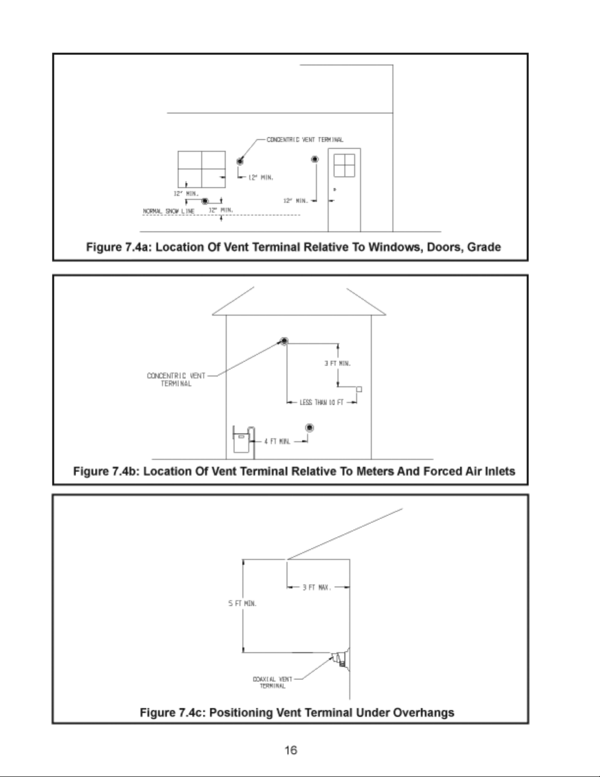
Vertical Vent Terminal Locations (Vent Option 5)7) - Observe the following limitations on the location of all
vertical vent terminals (see Figure 7.7):
The top of the vent pipe must be at least 2 feet above any object located within 10 feet.•
The bottom of the air inlet terminal must be at least 12” above the normal snow accumulation that can be •
expected on the roof. The terminal used in V ent Option #5 has a fixed distance above the storm collar of
19”. If a greater distance is needed to provide the clearance above the snow line, build a chase on the
roof and mount the vertical terminal on top of the chase.
Wall thimbles8) – Concentric vent has a “zero” clearance to combustibles and therefore does not require the
use of wall thimbles.
Pitch of Horizontal Piping9) - Pitch all horizontal piping so that any condensate which forms in the piping will run
towards the boiler. Pitch Crown horizontal concentric venting 5/8” per foot
Supporting Pipe10) - Vertical and horizontal sections of pipe must be properly supported. Support Crown
concentric venting near the female end of each straight section of pipe. Exception: Vertical runs of concentric
pipe in an unused chimney (Figure 7.36) need only be supported at the terminal and at the base of the run.
Table 7.6: Summary Of Vertical Venting Options
VENT OPTION # 5 6
CLASSIFICATION USED IN THIS
MANUAL
ILLUSTRATED IN FIGURE 7.7
VENT PIPE PENETRATION
THROUGH STRUCTURE
VENT PIPE SIZE
INLET AIR ORIFICE SIZE
MAX. VENT LENGTH
MIN. VENT LENGTH
VENT TERMINAL
VERTICAL
CONCENTRIC
ROOF
80/125mm
CONCENTRIC
82mm
27ft - 10in
6in
CROWN #230532
CONCENTRIC
TERMINAL (TABLE
7.3b)
RESERVED FOR
FUTURE USE
CROWN 80/125 mm
VENT MATERIAL
VENT COMPONENTS
SHOWN IN TABLE
7.3b
17
Page 20
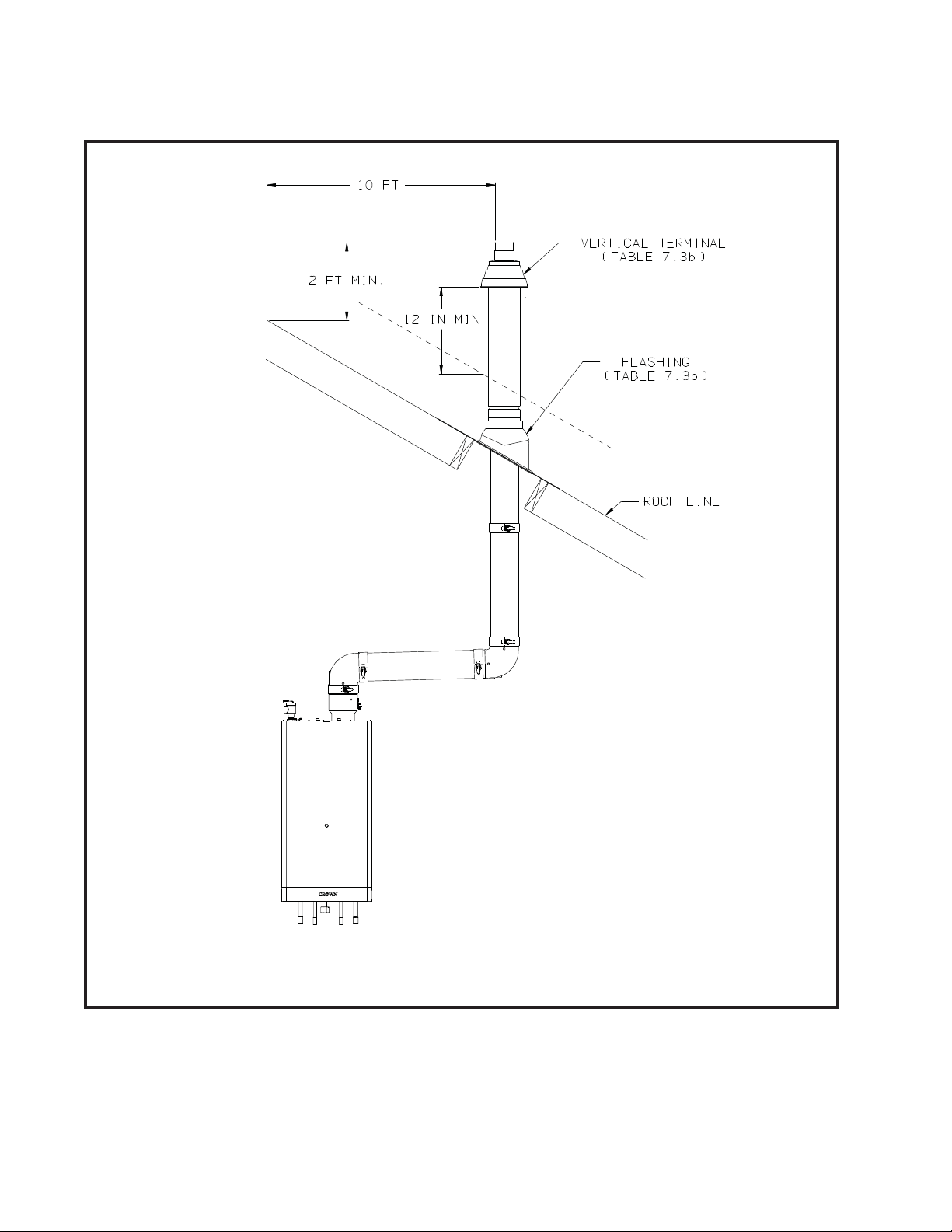
Figure 7.7: Vertical Concentric Vent System (Vent Option 5)
18
Page 21

B. Removing an Existing Boiler From a Common Chimney
Read this only if the MWC boiler is replacing an existing boiler that is being removed from a common
chimney. This section does not apply to the installation of a MWC boiler.
In some cases, when an existing boiler is removed from a common chimney, the common venting system
may be too large for the remaining appliances. At the time of removal of an existing boiler, the following
steps shall be followed with each appliance remaining connected to the common venting system placed
in operation, while the other appliances remaining connected to the common venting system are not in
operation.
(a) Seal any unused openings in the common venting system.
(b) Visually inspect the venting system for proper size and horizontal pitch and determine there is no
blockage or restriction, leakage, corrosion and other defi ciencies which could cause an unsafe
condition.
(c) Insofar as practical, close all building doors and windows and all doors between the space in which
all the appliances remaining connected to the common venting system are located and other
spaces of the building. Turn on clothes dryers and any appliance not connected to the common
venting system. Turn on any exhaust fans, such as range hoods and bathroom exhausts, so they
will operate at maximum speed. Do not operate a summer exhaust fan. Close fi replace dampers.
(d) Place in operation the appliance being inspected. Follow the lighting instructions. Adjust
thermostat so the appliance will operate continuously.
(e) Test for spillage at the draft hood relief opening after 5 minutes of main burner operation. Use
the fl ame of a match or candle, or smoke from a cigarette, cigar, or pipe.
(f) After it has been determined that each appliance remaining connected to the common venting
system properly vents when tested as outlined above, return doors, windows, exhaust fans,
fi replace dampers and any other gas-burning appliances to their previous condition of use.
(g) Any improper operation of the common venting system should be corrected so the installation
conforms with the National Fuel Gas Code, ANSI Z223.1.
Natural Gas and Propane Installation Code.
common venting system, the common venting system should be re sized to approach the minimum
size as determined using the appropriate tables in Part 11 of the National Fuel Gas Code, ANSI
Z223.1.
/NFPA 54 and/or CAN/CSA B 149.1
When re-sizing any portion of the
/NFPA 54 and/or CAN/CSA B 149.1
WARNING
Never common vent a MWC boiler with other appliances.
19
Page 22

Page 23
Page 24
Page 25
Page 26
Page 27
Page 28

Page 29

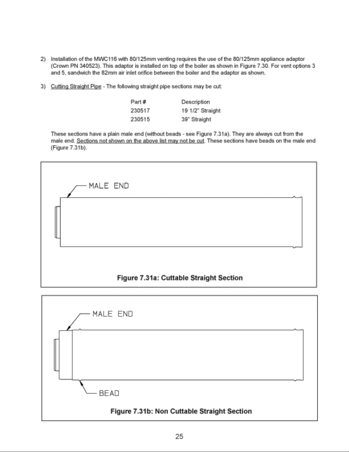
Figure 7.33a: Joining Cuttable Pipe
Figure 7.33b: Joining Non-Cuttable Pipe
27
Page 30

Page 31

Figure 7.34c: Cutting Inner Pipe Of 80/125mm Horizontal Terminal
Figure 7.34d: Completing 80/125mm Horizontal Terminal Installation
29
Page 32

Page 33

Figure 7.35b: Cutting Vertical Terminal
Figure 7.35c: Completing Vertical Terminal Installation
31
Page 34

WARNING
Do not attempt to construct a vertical vent system inside a chimney that is used to vent a •
fi replace or other appliances.
Do not attempt to construct a vertical vent system inside a chimney fl ue adjacent to another •
fl ue used by a fi replace or other appliances.
Figure 7.36: Chimney Chase Installation
32
Page 35

Page 36

VIII Gas Piping
Gas piping to the boiler must be sized to deliver adequate gas for the boiler to fi re at the nameplate input at
an inlet pressure between the minimum and maximum values shown on the rating plate. For more information
on gas line sizing, consult the utility or the National Fuel Gas Code
Natural Gas and Propane Installation Code.
The gas line is connected to the boiler using the 3/4” NPT female connection in the tailpiece shown in Figure
8.1. This tailpiece is supplied in the boiler’s fi tting package, along with the fi ber gasket shown.
Figure 8.2 shows the fi nished gas piping connection to the MWC boiler. A sediment trap must be installed
upstream of all gas controls. Install the factory provided manual shut-off valve outside the jacket with a ground
joint union as shown.
The boiler and its gas connection must be leak tested before placing the boiler in operation. When doing this,
the boiler and its individual shut-off must be disconnected from the rest of the system during any pressure
testing of that system at pressures in excess of 1/2 psi. When pressure testing the gas system at pressures of
1/2 psi or less, isolate the boiler from the gas supply system by closing its individual manual shut-off valve.
ANSI Z223.1
/NFPA 54 and/or CAN/CSA B 149.1
Figure 8.1: Gas Tailpiece Installation
34
Page 37

Figure 8.2: Gas Connection To Boiler
35
Page 38

Page 39

Page 40

Page 41

Page 42

Page 43

Page 44

Page 45

Page 46

Page 47

Figure 10.3: MWC116E*T (Combi) Internal DHW-Side Piping Schematic
45
Page 48

XI Wiring
WARNING
All wiring and grounding must be done in accordance with the authority having jurisdiction
or, in the absence of such requirements, with the National Electrical Code (ANSI/NFPA 70),
and / or, the Canadian Electrical Code Part I ,CSA C22.1,Electrical Code.
All electrical connections are line voltage (120 V AC) and are located under the cover on the cover on the top of the 1)
control box (Fig 1 1.1). To access these connections, use the following procedure:
Remove the three screws on the top of the front jacket panel and lift off the panel. a)
There are three screws in the bottom of each side jacket panel: two near the front and one near the back. b)
Remove the two screws near the front and loosen the screw near the back.
Spread the side jacket panels apart slightly , slide the control box forward and then rotate the control box down c)
as shown in Figure 1 1.1.
Remove the cover shown in Figure 1 1.1 to access the electrical connections. d)
Crown supplies the “Whip” shown in Figure 1 1.2 to route the power and thermostat wiring from an installer supplied 2)
junction box into the boiler’s control box. This Whip is designed to provide proper strain relief at the boiler and also
permits the control box to be easily slid in and out of the boiler with all wiring connections intact. A 7/8 hole is located
in the metal rail behind the control box as shown in Figure 1 1.3. Power and thermostat wiring is routed into the boiler
from underneath (Figure 11.5) and the BX connector on the “boiler end” of the Whip is secured in this 7/8” opening.
Route the whip leads into the electrical connection compartment. DO NOT CUT THE WHIP LEADS ON THE 3)
BOILER END.
Two terminal blocks are located in the electrical connection compartment: one for power connections and one for the 4)
thermostat connections. Figure 1 1.3 shows the location of these terminal blocks in the connection compartment.
Connect the whip leads to the terminals as shown in Figure 1 1.4:5)
Whip Color To Factory Wire Color Description
Black Brown 120VAC “Hot”
White Blue 120 VAC Neutral
Green Green/Yellow Ground
Orange (either) Blue 120V AC Thermostat
Orange (either) Red 120VAC Thermostat
Important: Remove the factory installed jumper from the thermostat terminals (Figure 10.4)
Reinstall the compartment cover removed in Step #1d.6)
Figure 1 1.5 shows connections at the junction box end of the whip. Provide a dedicated circuit for the boiler with 7)
at least one emergency shut-off switch located in accordance with applicable codes. The thermostat connections
provided are 120V AC. If a thermostat is directly connected to these leads, it and all intervening wiring, must be
suitable for use with 120V AC power. If it is desired to control the boiler with a low voltage thermostat, or other low
voltage control system, use a fan center to do so as shown in Figure 1 1.6
WARNING
Attempting to directly connect a low voltage thermostat and/or low voltage wiring to the orange
thermostat leads could cause property damage and/or create hazard of fi re or electricutuion.
46
Page 49

Page 50

Page 51

Page 52

Page 53

Page 54

Page 55

Page 56

Page 57

Page 58

MWC Series Lighting and Operating Instructions
FOR YOUR SAFETY READ BEFORE OPERATING
WARNING: If you do not follow these instructions exactly, a fire or explosion may result
causing property damage, personal injury or loss of life.
A This appliance does not have a pilot. It is
equipped with an ignition device which
automatically lights the burner. Do not try to
light the burner by hand.
B BEFORE OPERATING smell all around the
appliance area for gas. Be sure to smell next
to the floor because some gas is heavier than
air and will settle on the floor.
WHAT TO DO IF YOU SMELL GAS
--- Do not try to light any appliance.
--- Do not touch any electric switch; do not use
any phone in your building.
--- Immediately call your gas supplier from a
neighbor’s phone. Follow the gas supplier’s
instructions.
OPERATING INSTRUCTIONS
1. STOP! Read the safety information above on
this label.
2. Turn off all electric power to the appliance.
3. Set the thermostat to lowest setting.
4. This appliance is equipped with an ignition
device which automatically lights the burner.
Do not
5. Close main gas shut off valve.
6. Wait five (5) minutes to clear out any gas.
Then smell for gas including near the floor. If
you smell gas STOP! Follow “B” in the safety
information above on this label.
If you don’t smell gas, go to next step.
7. Open the main gas shut off valve and the
valve on the domestic cold water inlet pipe.
8. Turn on the electricity supply to the boiler,
switching on the circuit breaker. The appliance
try to light the burner by hand.
--- If you cannot reach your gas supplier, call the
fire department.
C Use only your hand to push in or turn the gas
control knob.
Never use tools. If the knob will not push in or
turn by hand, don’t try to repair it, call a
qualified s ervice technician.
Force or attempted repair may result in a fire
or explosion.
D Do not use this appliance if any part has been
under water. Immediately call a qualified
service technician to inspect the appliance and
to replace any part of the control system and
any gas control which has been under water.
operation light 1 (figure 1) will flash every 4
seconds (stand--- by condition).
9. If the boiler is to be used for c.h and d.h.w
position the function selector 2 as in figure 2.
The appliance operation light 1 will flash every
2 seconds (operating boiler).
Position the knobs 2 and 3 for the desired c.h.
and d.h.w. temperature (for detailed
information see the user manual).
10.If the boiler is to be used for d.h.w. only
position the function selector 2 as in figure 3.
The appliance operation light 1 will flash every
2 seconds (operating boiler).
Position the knob 3 for the desired d.h.w.
temperature (for detailed information see the
user manual).
11.If the appliance will not operate, follow the
instructions “To turn off gas to appliance” and
call your service technician or gas supplier.
1
2 1 2 1 2
Figure 1 Figure 2 Figure 3
3 (Combi Only)
TO TURN OFF GAS TO APPLIANCE
1. Turn off all electric power to the appliance if
service is to be performed.
2. Turn the boiler off by setting the function
selector 2 to the position shown in figure 1.
3 (Combi Only)
3. Set the thermostat or other operating control
to lowest setting
4. Close the main gas gas shut off valve and the
valve on the domestic cold water inlet
pipe.
56
Page 59

Page 60

Page 61

Page 62

Page 63

Page 64

Page 65

Figure 14.1: Removing Combustion Chamber Cover
WARNING
Soot deposits in the fl ue passages are a sign that the boiler may be operating at high carbon
monoxide (CO) levels. After cleaning the boiler of soot deposits, check the CO level in the fl ue gas
to insure that the boiler is operating properly.
If it is necessary to check CO, use a combustion analyzer, or other instrument which is designed
to measure CO in fl ue gas (see Start-up section). A CO “sniffer” designed for testing CO levels in
ambient air cannot be used to check boiler combustion.
A normal CO reading for an MWC series boiler is less than 50ppm (0.005%). A higher reading is
indicative of a combustion problem.
Some causes of excessive CO include:
• Incorrectly sized or drilled burner orifi ce
• Partially plugged fl ue passages
• Improper manifold pressure
• Partial blockage of vent or intake system
• Foreign material in burner venturis or burner ports
• Disconnected regulator reference tube
• Damaged fan impeller or housing
• Damaged or missing inducer or fl ue gas gaskets
• Distorted or missing combustion chamber or fl ue collector components.
• Flue gas recirculation in damaged or improperly assembled concentric venting
Inspect the burner ports for debris. The burner can be cleaned with a soft brush. If the burner shows signs of e.
deterioration, replace it.
Inspect the electrodes and fl ame rod for deposits. Clean as necessary. f.
Disconnect and remove the inducer from the boiler. The inducer is equipped with sealed ball bearings and g.
does not require lubrication. Inspect the impeller and the pressure switch venturi (Figure 14.2) for dirt or
debris. Clean as necessary with a soft brush.
Inspect the h. secondary (stainless steel) heat exchanger coil for debris. Clean as necessary by fl ushing with
clean water. A soft nylon brush may be used in accessible areas. Drain and fl ush the inside of the heat
exchanger and condensate collector as required. Do not use any cleaning agents or solvents.
Reinstall the inducer. If either of the inducer gaskets show signs of deterioration, replace them.i.
Inspect the vent system and terminal for obstructions and clean as necessary .j.
k. For direct vent appliances, proper reassembly and resealing of the vent-air intake system.
Inspect internal boiler piping for leaks and/or deteriorating gaskets. Repair as necessary . l.
Remove, inspect, and clean the condensate trap (Figure 14.3). Disconnect the wires from the trap. Use m.
pliers to compress the spring clip on the drain hose (the hose leading from the secondary heat exchanger)
and slide it upwards. Disconnect the drain hose from the trap. After removing the condensate trap from the
boiler, disassemble the trap in a tray or pan, being careful to note the way in which the fl oat ball and
retainer fi t into the trap. Flush all parts of the trap with water and reassemble. Reinstall the trap on the boiler.
Reinstall the combustion chamber cover, inner cover, and all jacket panels and any wiring removed during n.
the inspection/.cleaning process.
Perform the start-up and checkout procedure described in Section XII of this manual. o.
fl oat ball
63
Page 66

Page 67

Page 68

Page 69

Page 70

Page 71

Page 72

Page 73

Page 74

Page 75

Page 76

Page 77

Connection pipes
10*
7
7
10*
7
79
* Not for model c.h. only
79
80*
81
80*
75
Page 78

Page 79

Page 80

Page 81

Page 82

Page 83

Key no. Description Spare part code
1 O-ring gasket 1,78x15,6 BI1001 131
2 Drainage valve BI1011 104
3 O-ring gasket 17,04x4,00 mm BI1212 112
4 Screw M5x25 mm - Hexagon socket cap BI1131 107
5 Return group kit (Model combi) BI1271 504
6 Domestic water restrictor BI1271 102
7 Flat gasket 3/4" BI1001 108
8 Toothed lock washer external 6,4 mm BI1001 124
9 Screw M6x8 mm - BZP RPH BI1001 123
10 Flat gasket 1/2" BI1001 106
11 Flow limiter 10 Litres/min BI1091 102
11A Flow limiter 12 Litres/min BI1091 103
11B Flow limiter 14 Litres/min BI1161 101
12 Magnetic fl ow switch and fi lter kit BI1271 501
13 D.h.w. fl ow switch BI1271 101
14 Exchanger Domestic Hot Water BI1001 102
15 O-ring gasket 1,78x12,42 mm by-pass pipe BI1001 115
16 By-pass pipe (Model combi) BI1271 100
17 O-ring gasket 18,64x3,53 mm KI1043 144
18 By-pass pipe fi xing fork BI1001 111
19 O-ring gasket 1,78x14 mm BI1001 129
20 O-ring gasket 2,62x23,47 mm BI1011 107
21 Diverter valve actuator BI1201 100
22 Diverter valve actuator fi xing spring BI1101 101
23 Diverter valve kit BI1141 501
24 O-ring gasket 2,7x13,6 mm BI1011 117
25 Flow group kit (Model combi) BI1251 503
26 O-ring gasket 9,25x1,78 mm (NTC) KI1001 128
27 Temperature probe (special) BI1001 117
28 Central heating pressure switch membrane BI1011 103
29 Central heating pressure switch disk BI1011 111
30 Central heating pressure switch spring BI1011 110
31 Screw M4x12 mm Stainless steel SCH BI1011 109
32 Microswitch guide bush BI1011 502
33 Microswitch kit BI1011 505
34 Microswitch box fi xing clip BI1011 105
35 Screw 2,9x13 mm AB self tapping BZP - RCH BI1011 108
36 By-pass kit BI1141 505
37 Condensing heat exchanger BI1262 122
38 O-ring gasket 2,62x17.86 mm BI1262 112
39 Condensing heat exchanger connection clip BI1172 101
40 Connection spring BI1262 117
41 Grommet BI1002 113
42 Condensate discharge pipe BI1262 110
43 Condensate trap (withdrawn) BI1262 118
44 O-ring gasket 1,9X16 mm BI1262 114
45 Main exchanger BI1262 135
46 O-ring gasket 17,04x3,53 KI1043 114
81
Page 84

Key no. Description Spare part code
47 Main exchanger connection clip BI1182 106
48 Condensing heat exchanger inlet pipe BI1262 136
49 Automatic air purger valve BI1212 107
50 Pump connection fork BI1262 116
51 Fork BI1262 120
52 Fork KI1042 101
53 Fork KI1042 115
54 Screw 5X16 BI1262 115
55 Pump (complete) BI1262 137
56 Pump gasket BI1172 113
57 Main exchanger outlet pipe (Model combi) BI1262 138
58 Probe holder BI1105 108
59 O-ring gasket 2,62X9,92 mm BI1262 113
60 Expansion vessel connection pipe BI1262 134
61 Flat gasket 3/8" O.D 15 mm, i.d. 8.5 mm BI1202 105
62 Condensing heat exchanger outlet pipe BI1262 107
63 Expansion vessel BI1182 105
64 Safety valve 30 psi BI1262 133
65 Safety valve connection pipe (Model combi) BI1262 132
66 Injectors with gaskets 130 - NG BI1203 502
66A Injectors with gaskets 85 - LPG BI1203 503
67 Burner BI1203 103
68 Detection electrode BI1123 102
69 Ignition electrode - right BI1123 103
70 Ignition electrode - left BI1123 101
71 Grommet BI1002 115
72 Tapping screw 3,5x9,5 mm recessed pan head BI1013 115
73 Taptite screw M4x8 mm Recessed pan head BI1013 111
74 Screw self tapping 3,9x9,5 mm type AB Recessed Pan Head BI1013 112
75 Gas valve BI1203 104
76 Gas pipe to the manifold BI1203 105
77 Tapping Screw ISO No8 B 4,2x9,5 Recessed Pan Head BI1013 110
78 Gas manifold with injectors NG BI1183 105
78A Gas manifold with injectors LPG BI1203 106
79 C.h. connection pipe BI1124 120
80 D.h.w. and d.c.w. connection pipe BI1124 118
81 Gas connection pipe BI1124 119
82 Full sequence control device BI1555 109
83 Fan and APS device BI1555 108
84 Temperature-pressure gauge BI1555 111
85 O-ring gasket 1,78 x 6,75 mm BI1475 119
86 Cover panel BI1555 112
87 Knob BI1555 113
88 Shaft BI1475 105
89 Control panel plug BI1475 110
90 Control panel box (Model combi) BI1555 114
91 Cable holder KI1066 208
92 Terminal block BI1475 109
82
Page 85

Key no. Description Spare part code
93 Screw 3,5x16 mm self tap RPH BI1165 101
94 Electronic control - ignition p.c.b. BI1555 107
95 Fuse 2AF BI1165 112
96 Service panel cover BI1475 111
97 Control panel cover BI1475 112
98 Screw 3,5X9,5 mm self tap RPH BI1615 104
99 Flame detection electrode cable BI1615 111
100 Detection to trap wiring BI1615 108
101 Full nut M5 Hexagon BI1035 111
102 Toothed lock washer external 5,3x10 mm stainless BI1035 110
103 Machine Screw M5x10 mm Recessed Pan Head BI1035 109
104 Trap to earth wiring BI1615 102
105 Ignition electrode cable BI1615 112
106 Ignition electrode cable BI1615 110
107 Pump-diverter valve cable (Model combi) BI1615 113
108 Flow switches, temp. probes and modulator cable (Model combi) BI1615 115
109 Ignition p.c.b. cable BI1615 109
110 Electronic control p.c.b.-fan and APS device connection cable BI1615 114
111 Power supply and external control cable BI1615 116
112 Earth wiring BI1615 117
113 Fan cable BI1615 107
114 Flue pipe gasket BI1016 104
115 Air restrictor d. 82 mm BI1406 124
116 Flue outlet gasket BI1406 112
117 Wall mounting plate BI1124 104
118 Air pressure switch BI1406 125
119 Venturi device tube BI1256 101
120 Air defl ector - right BI1406 114
121 Side case panel BI1416 100
122 Combustion chamber side panel BI1326 100
123 Combustion chamber front panel BI1406 119
124 Front case panel BI1406 127
125 Window (glass + rubber frame) BI1206 118
126 Sealed chamber lid BI1406 105
127 Screw 4,8x13 mm AB self tapping RPH BZP BI1336 114
128 Sealed chamber gaskets kit BI1406 500
129 Combustion chamber rear panel BI1326 108
130 Fan holder bracket BI1406 120
131 Fan inlet gasket BI1406 111
132 Fan BI1406 126
133 Wire saddle BI1406 123
134 Flue hood BI1406 122
135 Fan outlet gasket BI1406 113
136 Venturi BI1406 128
137 Flue pressure switch tube BI1016 107
138 Air switch pressure test point BI1036 101
139 Overheat thermostat BI1262 139
140 Screw M4x5 mm - BZP RPH BI1406 117
83
Page 86

Page 87

2. APPROVED CARBON MONOXIDE DETECTORS.
Each carbon monoxide detector as required in accordance with the above provisions shall comply with
NFPA 720 and be ANSI/UL 2034 listed and IAS certifi ed.
3. SIGNAGE.
A metal or plastic identifi cation plate shall be permanently mounted to the exterior of the building at a mini-
mum height of eight (8) feet above grade directly in line with the exhaust vent terminal for the horizontally
vented gas fueled heating appliance or equipment. The sign shall read, in print size no less than one-half
(1/2) inch in size, “GAS VENT DIRECTLY BELOW. KEEP CLEAR OF ALL OBSTRUCTIONS”.
4. INSPECTION.
The state or local gas inspector of the side wall horizontally vented gas fueled equipment shall not approve
the installation unless, upon inspection, the inspector observes carbon monoxide detectors and signage
installed in accordance with the provisions of 248 CMR 5.08(2)(a)1 through 4.
(b) EXEMPTIONS: The following equipment is exempt from 248 CMR 5.08(2)(a)1 through 4:
1. The equipment listed in Chapter 10 entitled “Equipment Not Required T o Be Vented” in the most current edition of NFPA 54 as adopted by the Board;
2. Product Approved side wall horizontally vented gas fueled equipment installed in a room or structure
separate from the dwelling, building or structure used in whole or in part for residential purposes.
(c) MANUFACTURER REQUIREMENTS - GAS EQUIPMENT VENTING SYSTEM PROVIDED. When the
manufacturer of Product Approved side wall horizontally vented gas equipment provides a venting
system design or venting system components with the equipment, the instructions provided by the
manufacturer for installation of the equipment and the venting system shall include:
1. Detailed instructions for the installation of the venting system design or the venting system components; and
2. A complete parts list for the venting system design or venting system.
(d) MANUFACTURER REQUIREMENTS - GAS EQUIPMENT VENTING SYSTEM NOT PROVIDED.
When the manufacturer of a Product Approved side wall horizontally vented gas fueled equipment does
not provide the parts for venting the fl ue gases, but identifi es “special venting systems”, the following
requirements shall be satisfi ed by the manufacturer:
1. The referenced “special venting system” instructions shall be included with the appliance or equipment installation instructions; and
2. The “special venting systems” shall be Product Approved by the Board, and the instructions for that
system shall include a parts list and detailed installation instructions.
(e) A copy of all installation instructions for all Product Approved side wall horizontally vented gas fueled
equipment, all venting instructions, all parts lists for venting instructions, and/or all venting design instructions shall remain with the appliance or equipment at the completion of the installation.
85
Page 88

 Loading...