

Page 1
!
!
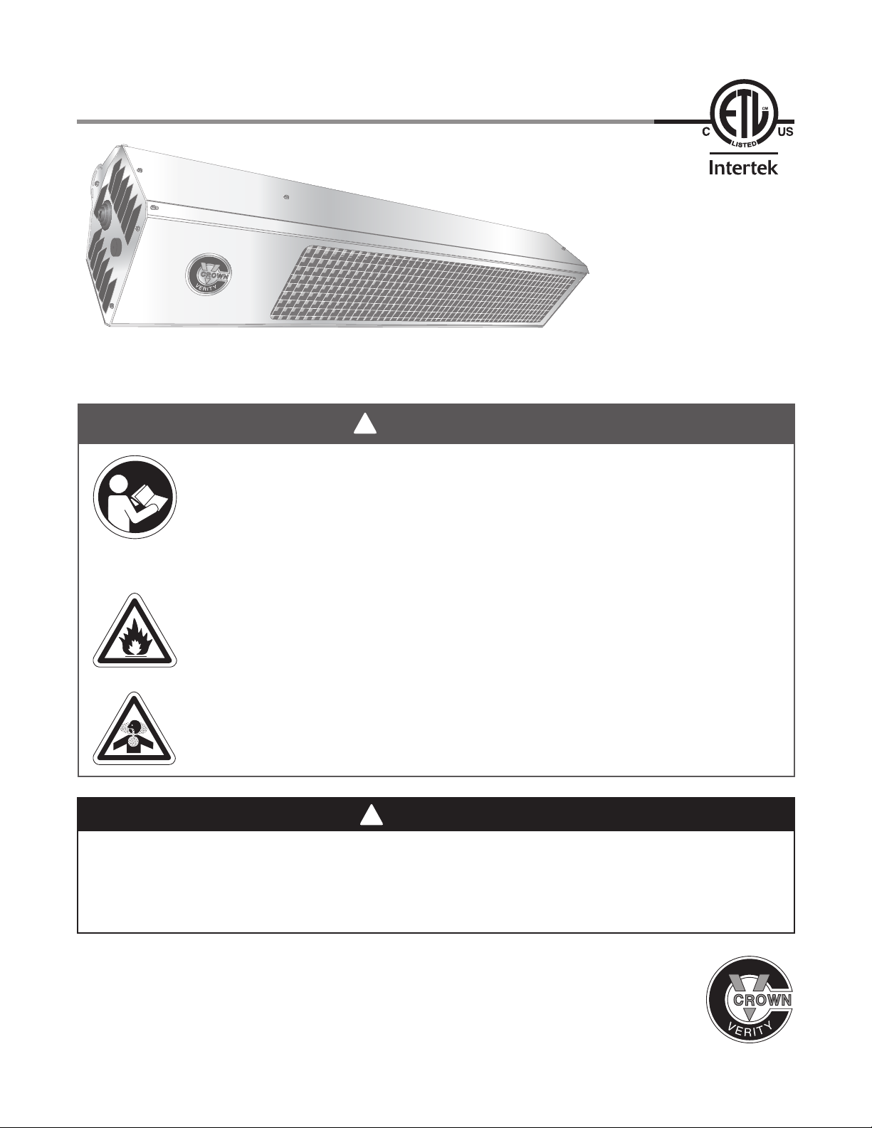
DSC Series Manual
!
Installation, Operation,
Maintenance and Parts
WARNING
Improper installation, adjustment, alteration, service or maintenance can cause
property damage, injury or death. Read and understand the installation, operating
and maintenance instructions thoroughly before installing or servicing this equipment.
This heater must be installed and serviced by trained gas installation and service
personnel only. Inspect the heater annually. Failure to comply could result in personal
injury, asphyxiation, death fire and/or property damage.
Storage of gasoline and other flammable vapors and liquids in the vicinity of this or
any other appliance may result in fire or explosion. Do not store or use gasoline or
other flammable vapors and liquids in the vicinity of this or any other appliance. An
LP cylinder not connected for use shall not be stored in the vicinity of this or any other
appliance. Maintain clearance to combustibles at all times.
For outdoor use only. This heater is not approved for use in any indoor residential
application. This includes, but is not limited to, attached garages, solarium, living
quarters, etc. Installation in residential indoor spaces may result in property damage,
asphyxiation, serious injury or death.
DANGER
If you smell gas:
1. Shut off gas to the appliance.
2. Extinguish any flame.
3. If odor continues, keep away from the appliance and immediately call your gas supplier or fire
department.
C R O W N V E R I T Y I N C .
37 Adams Boulevard, Brantford, Ontario, Canada N3S 7V8
tel 519.751.1800 or 888.505.7240 fax 519.751.1802 e-mail [email protected] web www.crownverity.com
Page 2

33
DSC Series
Contents
1.0 Safety. . . . . . . . . . . . . . . . . . . . . . . . . . . . . . . . . . . . . . . . . . . . . . . . . . . . . . . . . . . . . . . . . . . . 3
Safety Symbols . . . . . . . . . . . . . . . . . . . . . . . . . . . . . . . . . . . . . . . . . . . . . . . . . . . . . . . 3
Applications . . . . . . . . . . . . . . . . . . . . . . . . . . . . . . . . . . . . . . . . . . . . . . . . . . . . . . . . . . 3
Clearance to Combustibles . . . . . . . . . . . . . . . . . . . . . . . . . . . . . . . . . . . . . . . . . . . . . . 4
Standards, Certifications and Government Regulations . . . . . . . . . . . . . . . . . . . . . . . . 6
Safety Signs and Labels . . . . . . . . . . . . . . . . . . . . . . . . . . . . . . . . . . . . . . . . . . . . . . . . 8
2.0 Installation . . . . . . . . . . . . . . . . . . . . . . . . . . . . . . . . . . . . . . . . . . . . . . . . . . . . . . . . . . . . . . . 9
Design . . . . . . . . . . . . . . . . . . . . . . . . . . . . . . . . . . . . . . . . . . . . . . . . . . . . . . . . . . . . . 9
Heater Mounting . . . . . . . . . . . . . . . . . . . . . . . . . . . . . . . . . . . . . . . . . . . . . . . . . . . . . . 10
Recommended Mounting Heights. . . . . . . . . . . . . . . . . . . . . . . . . . . . . . . . . . . . . . . . . 11
Gas Supply . . . . . . . . . . . . . . . . . . . . . . . . . . . . . . . . . . . . . . . . . . . . . . . . . . . . . . . . . . 13
Gas Connection. . . . . . . . . . . . . . . . . . . . . . . . . . . . . . . . . . . . . . . . . . . . . . . . . . . . . . . 14
Leak Testing . . . . . . . . . . . . . . . . . . . . . . . . . . . . . . . . . . . . . . . . . . . . . . . . . . . . . . . . . 16
Electrical Requirements . . . . . . . . . . . . . . . . . . . . . . . . . . . . . . . . . . . . . . . . . . . . . . . . 17
Wiring Diagrams . . . . . . . . . . . . . . . . . . . . . . . . . . . . . . . . . . . . . . . . . . . . . . . . . . . . . . 18
Ventilation . . . . . . . . . . . . . . . . . . . . . . . . . . . . . . . . . . . . . . . . . . . . . . . . . . . . . . . . . . . 19
3.0 Operation . . . . . . . . . . . . . . . . . . . . . . . . . . . . . . . . . . . . . . . . . . . . . . . . . . . . . . . . . . . . . . . . 20
Sequence of Operation . . . . . . . . . . . . . . . . . . . . . . . . . . . . . . . . . . . . . . . . . . . . . . . . . 20
4.0 Maintenance . . . . . . . . . . . . . . . . . . . . . . . . . . . . . . . . . . . . . . . . . . . . . . . . . . . . . . . . . . . . . . 21
Periodic Maintenance . . . . . . . . . . . . . . . . . . . . . . . . . . . . . . . . . . . . . . . . . . . . . . . . . . 21
Service Access Panel Removal . . . . . . . . . . . . . . . . . . . . . . . . . . . . . . . . . . . . . . . . . . 22
Troubleshooting Guide . . . . . . . . . . . . . . . . . . . . . . . . . . . . . . . . . . . . . . . . . . . . . . . . . 23
Maintenance Log. . . . . . . . . . . . . . . . . . . . . . . . . . . . . . . . . . . . . . . . . . . . . . . . . . . . . . 24
5.0 Parts . . . . . . . . . . . . . . . . . . . . . . . . . . . . . . . . . . . . . . . . . . . . . . . . . . . . . . . . . . . . . . . . . . . . 26
6.0 Limited Warranty . . . . . . . . . . . . . . . . . . . . . . . . . . . . . . . . . . . . . . . . . . . . . . . . . . . . . . . . . . 28
2
Page 3
!
!
!
DSC Series
!
!
!
1.0 Safety • Safety Symbols • Applications
1.0 Safety
WARNING
Improper installation, adjustment, alteration, service or maintenance can cause
property damage, serious injury or death. Read and understand the installation,
operating and maintenance instructions thoroughly before installing or servicing this
equipment. Only trained, qualified gas installation and service personnel may install or
service this equipment.
Safety Symbols
Safety is the most important consideration during installation, operation and maintenance of the infrared
heater. You will see the following symbols and signal words when there is a hazard related to safety or
property damage.
Danger indicates a hazardous situation which, if
DANGER
not avoided, will result in death or serious injury.
Warning indicates a potentially hazardous situation
!
WARNING
!
CAUTION
NOTICE
which, if not avoided, could result in death or injury.
Caution indicates a potentially hazardous situation
which, if not avoided, could result in minor or
moderate injury.
Notice indicates a potentially hazardous situation
which, if not avoided, could result in property
damage.
Applications
This is not an explosion proof heater. Consult your local fire marshal, insurance carrier and other
authorities for approval of the proposed installation.
Commercial / Industrial
This patio heater is specifically designed to provide heated comfort in an outdoor environment. When
properly integrated into a patio design, the heaters generally increase the comfort levels.
Outdoor Residential
This heater may only be used in outdoor residential applications and is NOT approved for use in any
indoor residential application. This includes, but not limited to, attached garages, living quarters, solarium,
etc. Consult the local fire marshal and/or insurance provider if unsure of your application.
WARNING
Not For Indoor Residential Use. Installation of a infrared heater system in
residential indoor spaces may result in property damage, serious injury or
death. In residential applications this heater may only be used outdoors.
33
Page 4
55
1.0 Safety • Clearance to Combustibles
DSC Series
Clearance to Combustibles
!
WARNING
Placement of explosive objects, flammable objects, liquids and vapors close
to the heater may result in explosion, fire, property damage, serious injury or
death. Do not store, or use, explosive objects, liquids and vapor in the vicinity
of the heater.
Failure to comply with the published clearances to combustibles could result in personal injury, death and/
or property damage.
A critical safety factor to consider before installation is the clearances to combustibles. Clearance to
combustibles is defined as the minimum distance you must have between the infrared surface, or
reflector, and the combustible item. Considerations must also be made for moving objects around the
infrared heater. The following is a partial list of items to maintain clearances from:
Combustible items: Moving Objects:
• Wood • Chemicals • Overhead doors • Hoists
• Paper • Wall or roof insulation • Vehicle lifts • Car wash equipment
• Fabric • Cranes
Hazards:
For maximum safety the building must be evaluated for hazards before installing the heater system.
Examples include, but are not limited to:
• Gas and electrical lines
• Combustible and explosive materials
• Chemical storage areas
• Areas of high chemical fume concentrations
• Provisions for accessibility to the heater
• Adequate clearances around air openings
• Combustion and ventilating air supply
!
CAUTION
In locations used for the storage of combustible materials, signs must be posted to specify
the maximum permissible stacking height to maintain the required clearances from the
heater to the combustibles. Signs must either be posted adjacent to the heater thermostats
or in the absence of such thermostats, in a conspicuous location.
Children and adults should be alerted to the hazards for high surface temperatures and should stay away
to avoid burns or clothing ignition.
Young children should be carefully supervised when they are in the same space as the heater.
• Vehicle parking areas
• Vehicles with lifts or cranes
• Storage areas with stacked materials
• Lights
• Sprinkler heads
• Overhead doors and tracks
• Dirty, contaminated environment
Clothing or other flammable materials should not be hung from the heater, or placed on or near the heater.
Any guard or other protective device removed for servicing the heater must be replaced prior to operating
the heater.
Installation and repair should be done by a qualified service person. The heater should be inspected
before use and at least annually by a qualified service person. More frequent cleaning may be required as
necessary. It is imperative that the control compartment, air passage ways and burner of the heater are
kept clean.
4
Page 5
DSC Series
1.0 Safety • Clearance to Combustibles
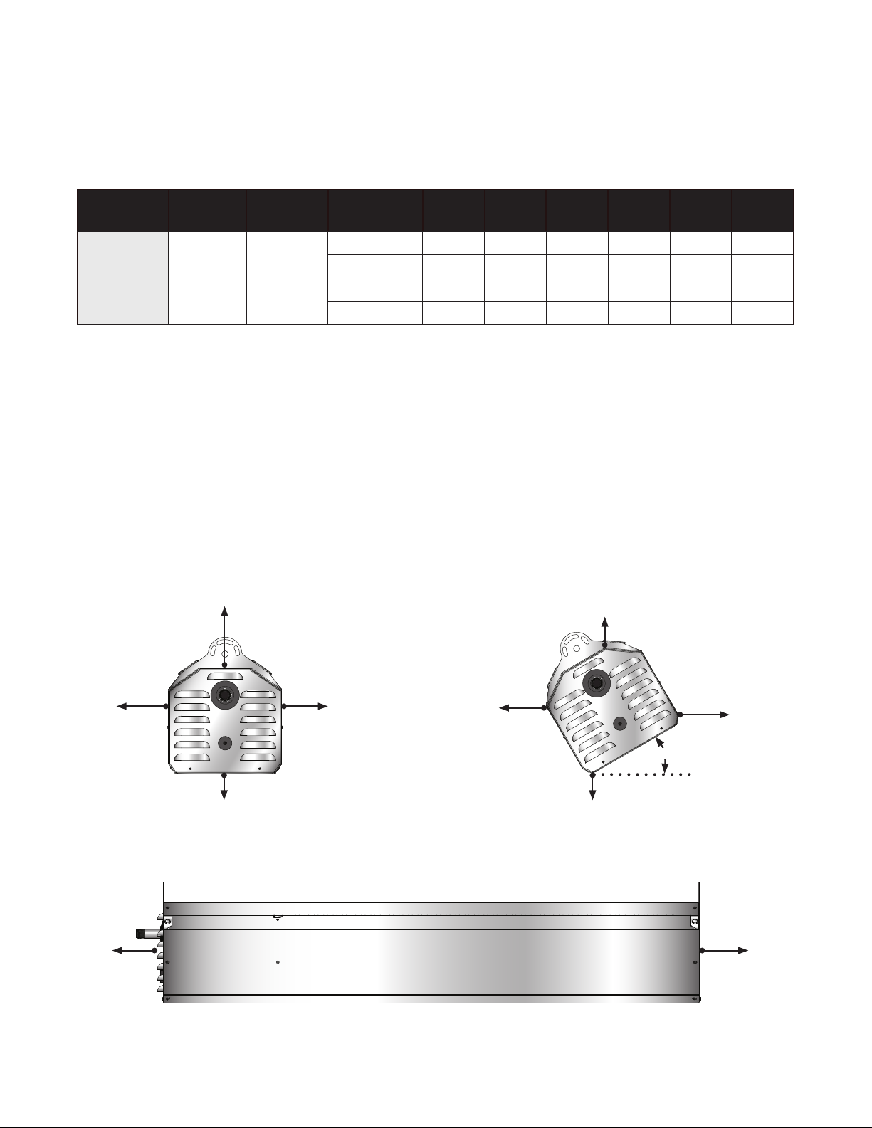
When installing the infrared heater system, the minimum clearances to combustibles must be maintained.
These distances are shown in Chart 1.1 and on the heater. If you are unsure of the potential hazards,
consult your local fire marshal, fire insurance carrier or other qualified authorities on the installation of gas
fired infrared heaters for approval of the proposed installation.
Chart 1.1 • Clearance to Combustibles in Inches (see Figure 1.1)
Mounting
Model No. BTU/h Voltage
DSC-31 31,000 24 VAC
DSC-34 34,000 24 VAC
Angle* Sides Back Top Below Ends Front
0° 18 N/A 13 48 12 N/A
30° N/A 18 18 40 12 36
0° 18 N/A 13 48 12 N/A
30° N/A 18 18 40 12 36
* Heaters mounted on an angle between 1° to 30° must maintain clearances posted for 0° or 30°;
whichever is greater.
Important! If the heater is mounted beneath a non-combustible surface an 8 in. minimum top clearance
must be maintained from the top of the heater to prevent overheating the controls.
Clearance to combustible distances represent a surface temperature of 90°F (32°C) above ambient
temperature. Ensure that building materials with a low heat tolerance (i.e, awnings, fabrics, plastics,
sprinklers, insulation) are protected against degradation. This may require the heater to be mounted at a
distance in excess of the published clearances to combustibles. Contact the factory or the building
material manufacturer for additional information.
Figure 1.1 • Clearance to Combustibles
Top (to ceiling)
Side
Below
END VIEW - 0° MOUNTING ANGLE
Side
Back
END VIEW - 30° MOUNTING ANGLE
Top
(to ceiling)
Front
30˚
Below
End End
SIDE VIEW
55
Page 6

77
1.0 Safety • Standards, Certifications and Government Regulations
!
DSC Series
Standards, Certifications and Governmental Regulations
The installation of this heater must comply with all applicable local, state and national specifications,
regulations and building codes (contact the local building inspector and/or fire marshal for guidance)
before installing the heater system.
In the absence of local codes, the installation must conform to the latest edition of the National Fuel Code
ANSI Z223.1 (NFPA 54).
Refer to the following standards and codes for application specific guidelines:
Public Garages:
The installation of this heater in public garages must conform with the Standard for Parking Structures,
ANSI/NFPA 88A (latest edition), and must be at least 8 ft. above the floor.
Aircraft Hangars:
The installation of this heater in aircraft hangars must conform with the Standard for Aircraft Hangars,
ANSI/NFPA 409 (latest edition). The heater must be installed at least 10 ft. above the upper wing
surfaces and engine enclosures of the highest aircraft which might be stored in the hangar. In areas
adjoining the aircraft storage area, the heaters must be installed at least 8 ft. above the floor. The heaters
must be located in areas where they will not be subject to damage by aircraft, cranes, moveable
scaffolding or other objects.
High Altitude:
The installation of this heater is approved, without modifications, for elevations up to 2,000 ft. above MSL
(sea level). Contact Crown Verity Inc. for installations above these elevations.
Gas Connection:
WARNING
An approved connector, suitable for the environment of equipment usage, is required. Visible or excessive
swaying, flexing and vibration of the gas connections must be avoided to prevent failure. Neither the gas
pipe nor the connector shall be placed in the flue discharge area or in direct contact with infrared rays. In
no case shall the gas supply support or bear weight of the heater.
To ensure your safety, and to comply with the terms of the warranty, all units must be installed in
accordance with these instructions. Under no circumstance should the gas supply line provide support to
the heater.
The gas supply to the infrared patio heater must be connected and tested in accordance with national,
state, provincial, and local codes along with the guidelines in the manual. In the United States refer to the
latest edition of the ANSI Z223.1 (NFPA 54) Standard; and in Canada, refer to the latest edition of the
CAN/ CGA B149.1 Standard.
Supply gas piping to the unit should conform to the local and national requirements for type and volume of
gas handled, and pressure drop allowed in the line. Avoid pipe sizes smaller than 1/2”.
6
Page 7

DSC Series
1.0 Safety • Standards, Certifications and Government Regulations
Electrical:
The heater, when installed, must be electrically grounded in accordance with the National Electrical Code
ANSI/NFPA 70 (latest edition). Under no circumstances is the electrical supply line to provide any
assistance in the suspension of the heater.
Ventilation:
This heater must be installed in accordance with the requirements set forth in this manual and with the
NFPA 54/ANSI Z223.1 National Fuel Gas Code (latest edition). See ventilation requirements on page 19
.
Crown Verity units comply or are certified by one or more of the following organizations or standards:
• CSA International Requirement (CSA 2.37).
• American National Standards Institute (ANSI Z83.26).
• Intertek (ETL)
• Occupational Safety and Health Act (OSHA).
• NFPA 54/ANSI Z223.1 - National Fuel Gas Code.
• NFPA 70/ANSI - National Electrical Code.
77
Page 8
99
1.0 Safety • Safety Signs and Labels
DSC Series
Safety Signs and Labels
It is important to provide warnings to alert individuals to potential hazards and safety actions. ANSI
Z83.26/CSA 2.37 requires you to post a sign specifying the maximum permissible stacking height to
maintain the required clearances from the heater to the combustibles near the heaters thermostat or in
absence of such thermostats in a conspicuous location.
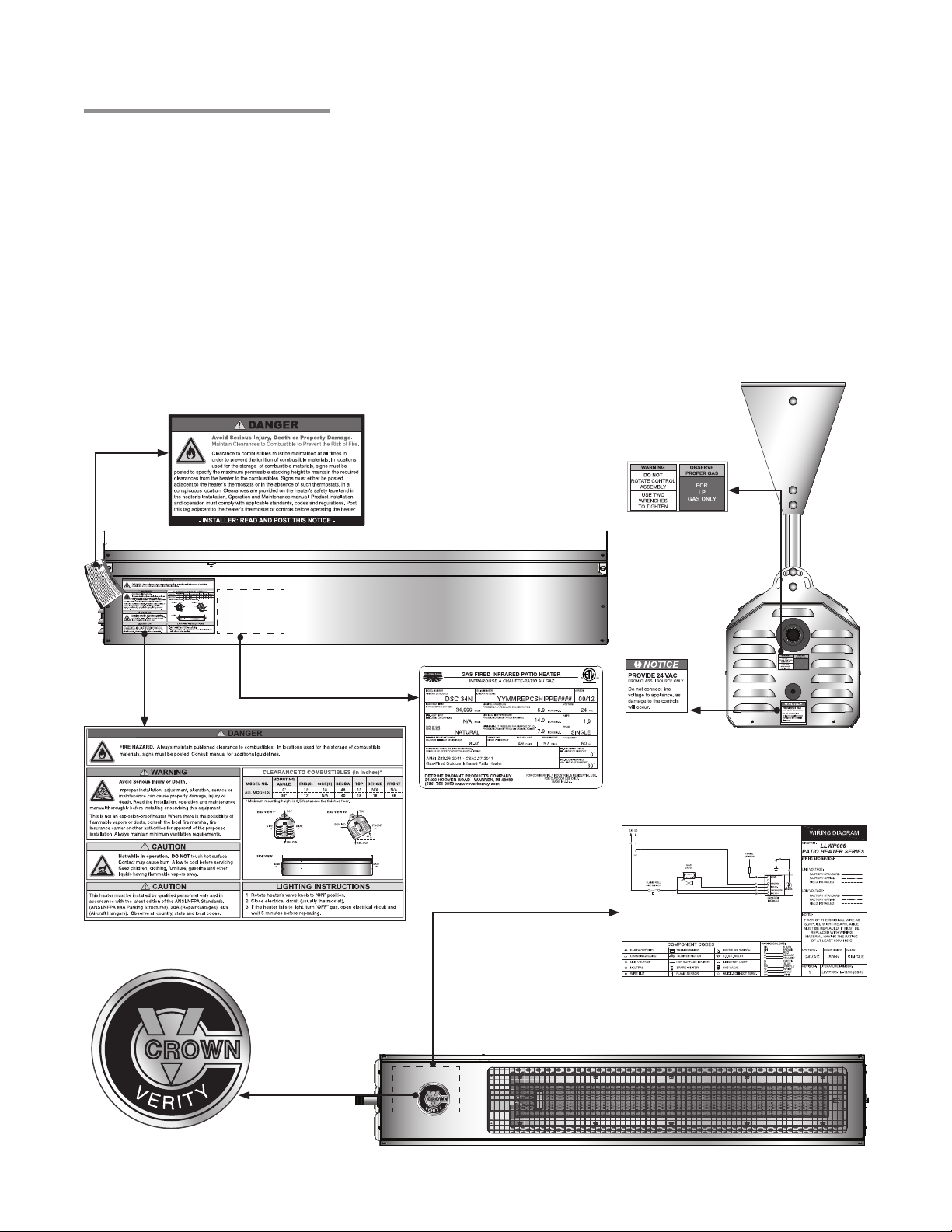
Safety warning labels must be maintained on the infrared heater. Illustrations of the safety labels, and their
locations, are pictured below. In locations used for the storage of combustible materials, signs must be
posted to specify the maximum permissible stacking height to maintain the required clearances from the
heater to combustibles. Signs must either be posted adjacent to the heater device or in the absence of
such control in a prominent location.
Figure 1.2 • Heater Safety Label Locations
F/N: LL01 - Clearance Safety Tag
(Affix adjacent to heater’s control
device).
F/N: LLPCL004
Clearance to Combustibles Label
Side Panel
SA MPLE
F/N: LLDR009 (NG)
F/N: LLDR010 (LP)
Gas Type Label
4002434
LLDR003
Provide 24 Volts
Rating Label
(inside panel)
End Panel
Logo Label
Wiring Diagram
(inside panel)
Front Panel
8
Page 9
!
DSC Series
!
2.0 Installation • Design
2.0 Installation
WARNING
Read and understand, the installation, operating and maintenance instructions
thoroughly before installing or servicing this equipment.
Only trained, qualified gas installation and service personnel may install or service
this equipment.
Design
Crown Verity Inc. Patio Heaters are designed specifically for comfort heating in an outdoor environment.
Examples of suitable applications include patios, porches, outdoor shopping areas, and outdoor
pathways. When used properly, the heaters will increase the comfort levels of its application. However, the
effectiveness of the heating will depend on many variables, such as air temperature, wind velocity, wind
barriers, mounting heights, and distance between heaters. To ensure a safe, properly designed heating
system, all of these variables should be considered prior to developing a layout for the infrared heaters.
It is important to note that the effectiveness of the heater may be diminished in environments with wind
velocities above 5 MPH. Wind barriers can be extremely effective in maintaining the effectiveness of the
heater and reducing the operational costs. However, if wind barriers are used, they must be designed in
such a way that allows for the necessary fresh air and ventilation for the proper heater operation. In
addition, all clearance to combustibles must be maintained at all times (See Chart 1.1 on page 5).
NOTICE
Radiant heat is capable of damaging or destroying certain materials or items. Do not store material or
items underneath the heater. Always maintain clearance to combustibles.
The infrared patio heaters may be laid out in a number of configurations depending on the structures
constraints of the application, heating requirements, and therefore, the basic recommendations of
installation. The minimum mounting height for all Crown Verity Patio Heaters is 6.5 feet above the finished
floor.
The heater must always be operated in a location that allows uniform air pressure around the heater. If
one part of the heater is located outside of a wind protected zone, the heater may not properly function or
damage to the heater may occur. Consideration should be taken on how the wind will affect the heaters
after installation. IMPORTANT: Fire sprinkler heads must be located at an appropriate distance from the
heater to avoid accidental discharge of the fire suppression system. This distance may exceed the
published clearance to combustibles (see Chart 1.1 on pg. 5). Certain applications will require the use of
high temperature sprinkler heads or relocation of the heaters.
CAUTION
Fire sprinkler systems containing propylene glycol, antifreeze or other potentially flammable substances
shall not be used in conjunction with this heater without careful consideration for and avoidance of
inadvertent discharge hazards. For further information consult NFPA 13. Always observe applicable state
and local codes.
99
Page 10
1111
2.0 Installation • Heater Mounting • Optional Mounting Kit
!
DSC Series
Heater Mounting
WARNING
Improper suspension of the infrared heater may result in collapse and persons being
crushed. Always suspend from a permanent part of the building structure that can support
the total force and weight of the heater.
Failure to maintain minimum clearance to combustibles may result in fire and/or explosion,
property damage, serious injury or death. Always maintain minimum clearances and post
signs or provided tags (F/N: LL01) where needed. Signs should state the hazards for the
particular application and be legible for the building occupants. Consult the factory or a
factory representative for additional information on signage compliance.
The heater shall be mounted in a fixed position attached from a structure that can evenly support the total
force and weight of the heater. The mounting means shall be independent of the gas and electrical supply
line. All hangars and bracket material shall be of noncombustible construction. Examples of suitable
material include, but are not limited to, Steel channel, steel tubing, threaded rod, or field fabricated
hangers that are adequate to bear the load. In some cases, the heater may need to be isolated from
vibration with the use of vibration isolating devices.
The heater must be level from side to side and can be set at an angle between 0° and 30° from horizontal.
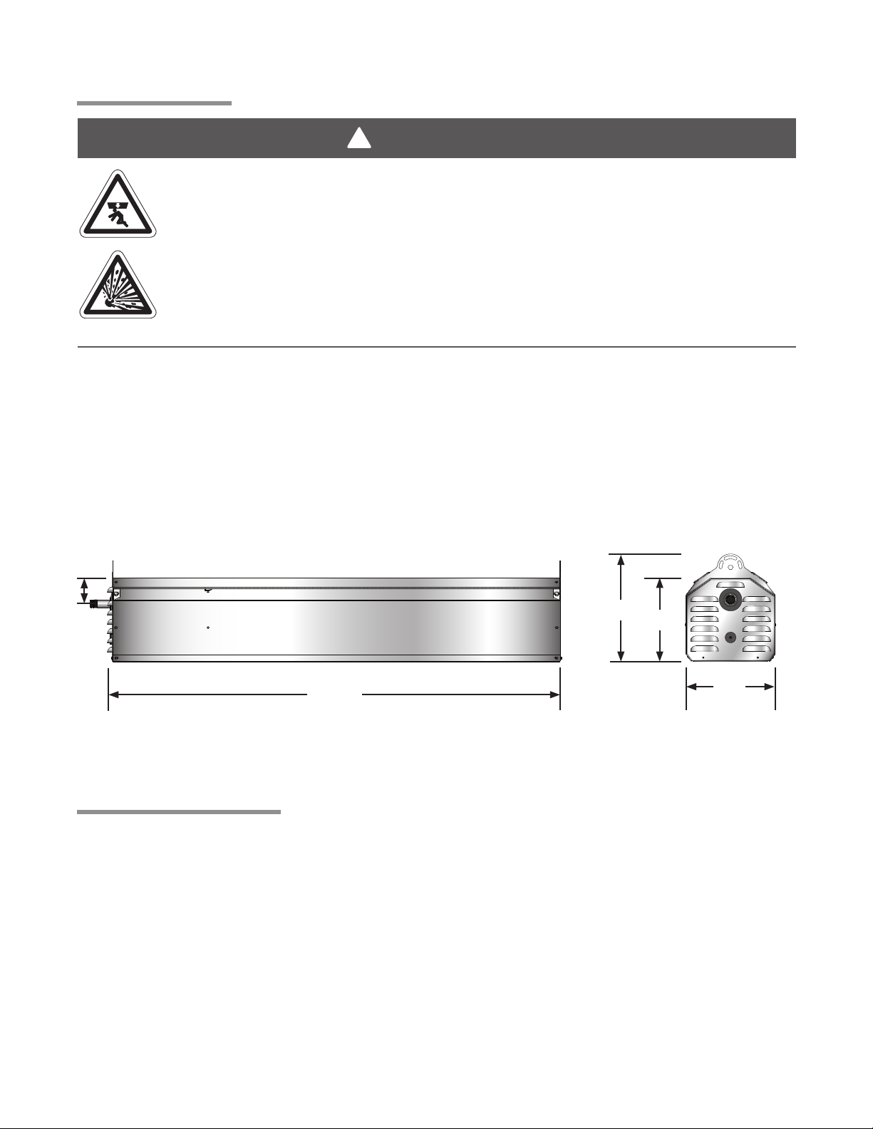
Figure 2.1 • Heater Dimensions
2.75”
10.875”
48.375”
9”
9”
END VIEWSIDE VIEW
Optional Mounting Kit
Optional adjustable mounting kits and brackets are available for the Patio Heater. Refer to the insert that
was packaged with the mounting brackets for complete installation instructions.
10
Page 11
DSC Series
!
2.0 Installation • Heater Mounting • Recommended Mounting Heights
Recommended Mounting Heights
WARNING
Heater must be installed at least 6.5 feet above the finished floor.
Chart 2.1 • Recommended Mounting Heights
Recommended
BTU/h
31,000 8’-0” to 12’-0” 8’ x 8’ 64 sq. ft.
34,000 8’-6” to 13’-0” 9’ x 9’ 81 sq. ft.
NOTE: This chart is provided as a guideline. Actual conditions dictate variances from this data.
Mounting Height
Approximate
Coverage Area
Approx. Coverage
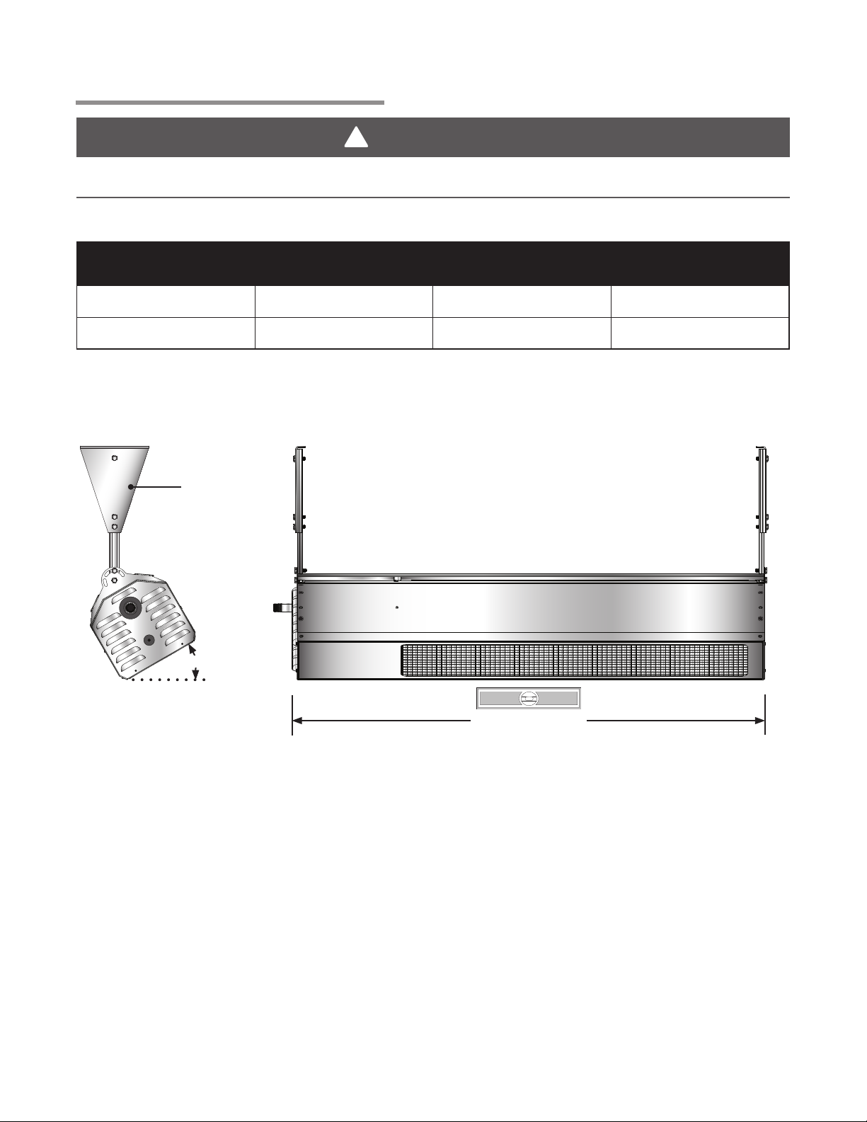
Figure 2.2 • Heater Orientation
Optional
Mounting
Bracket
End
0-30°
(sq. ft.)
End
Level end to end
1111
Page 12
1313
2.0 Installation • Heater Mounting
DSC Series
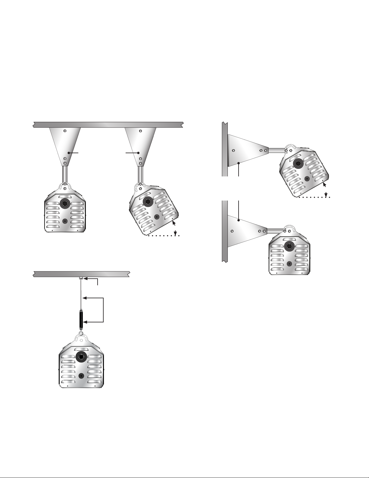
Figure 2.3 shows different types of mounting configurations. Depending on the type of mounting you use,
be sure to:
1 Prepare mounting surface. If necessary, weld blocks to mounting structure, drill holes, etc.
2 Fasten beam clamp, screw hook or other type of suspension anchor to hanging point.
3 Attach threaded rod and turnbuckle to anchor. Check that it is securely attached.
4 Attach heater to turnbuckle. Adjust turnbuckle until the heater is level and equal weight distribution is
achieved. Threaded rod must be straight up and down, do not install threaded rod at an angle.
Figure 2.3 • Heater Mounting
Optional
Mounting bracket
attached to ceiling.
Optional Mounting
bracket attached to
wall.
30° Mounting Angle
30°
0°
Mounting Angle
30°
30°
Mounting Angle
0° Mounting Angle
Bar Joist Clip
Rigid threaded rod
and turnbuckle
(field supplied)
12
Page 13
DSC Series
2.0 Installation • Gas Supply
Gas Supply
The gas supply to the infrared patio heater must be connected and tested in accordance with national,
state, provincial, and local codes along with the guidelines in the manual. In the United States refer to the
latest edition of the ANSI Z223.1 (NFPA 54) standard; and in Canada, refer to the latest edition of the
CAN/ CGA B149.1 Standard.
!
WARNING
Improperly connected gas lines may result in fire, explosion,
poisonous fumes, toxic gases, asphyxiation and death.
Connect gas lines in accordance to national, state, provincial
and local codes.
Supply gas piping to the unit should conform to the local and national requirements for type and volume of
gas handled, and pressure drop allowed in the line. Avoid pipe sizes smaller than 1/2”.
NOTICE
The total input to the appliance must fall within +/- 5% of the rated input as indicated on the rating plate.
Otherwise the burner may prematurely fail.
IMPORTANT! Before connecting the gas supply to the heater:
• Verify that the heaters’ gas type (as listed on the rating plate) matches that of your application and the
installation complies with national and local codes and requirements of the local gas company.
• Unless otherwise noted on the rating plate, the infrared heater is designed and orificed to operate on
standard BTU gas. Contact the factory if utilizing non-standard BTU gas.
• Check that the gas piping and service has the capacity to handle the total gas consumption of all the
heaters being installed, as well as any other gas appliances being connected to the supply line.
• Check that the main gas supply line is of proper diameter to supply the required fuel pressures.
• If utilizing used pipe, verify that its condition is clean and comparable to a new pipe. Test all gas
supply lines in accordance with local codes.
The gas outlet must be in the same space as the appliance installation, and must be accessible. It may
not be concealed within or run through any wall, floor or partition. When installing the heater in a corrosive
environment (or near corrosive substances), use a gas connector suitable for the environment. Do not
use the gas piping to electrically ground the heater.
This heater is equipped to connect to ½” NPT gas pipe. All piping must be installed in accordance with the
requirements outlined in the National Fuel Gas Code ANSI/Z223.1 (latest edition) or CSA B149.1 and
B149.2. Support all gas piping with pipe hangers, metal strapping, or other suitable material. Do not rely
on the heater to support the gas pipe.
1313
Page 14
1515
2.0 Installation • Gas Supply • Gas Connection
!
!
!
When connecting gas piping to the unit, the use of a thread joint compound is required. The thread
compound (pipe dope) shall be resistant to the action of liquefied petroleum gas or any other chemical
constituents of the gas to be conducted through the piping. Use of Teflon® tape is not permitted.
Install a ground joint union with a brass seat and a manual shut-off valve adjacent to the unit for
emergency shut-off and easy servicing of the controls. A 1/8” NPT plugged tap that is accessible for a test
gauge connection is also recommended as illustrated in Figures 2.4 and 2.5.
A sediment trap must be installed in the supply line in the lowest spot prior to connecting to the heater.
The trap length shall be at least three inches long. Ideally, the trap would be installed as close as possible
to the shut-off.
Chart 2.2 • Gas Consumption and Manifold Pressure (Inches W.C.)
DSC Series
Minimum
Manifold
Model No. Input
DSC-31N
DSC-31P
DSC-34N
Pressure Equivalents: 1 inch W.C. equals .058 oz./sq. in. equals 2.49 Mbar.
31,000 6.0” W.C. 7.0” W.C. 14.0” W.C. 29.5 0.43 2.35 mm
31,000 10.0” W.C. 11.0” W.C. 14.0” W.C. 12.4 0.34 1.65 mm
34,000 6.0” W.C. 7.0” W.C. 14.0” W.C. 32.4 0.47 41 DMS
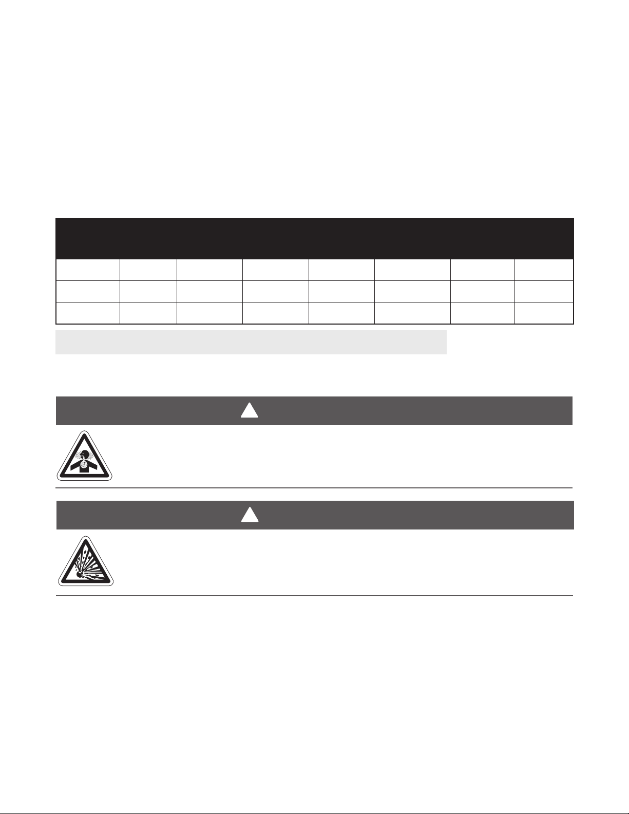
Pressure
Inlet
Pressure
Maximum
Inlet
Pressure
Gas
Consumption
(CFH)
To connect the gas:
!
WARNING
Improperly connected gas lines may result in serious injury or death, explosion,
poisonous fumes, toxic gases, asphyxiation. Connect gas lines in accordance to national,
state, provincial and local codes.
WARNING
Gallons per
Hour
Orifice
Size
Conditions such as wind drafts or other variables can cause movement of the heater and
may require it to be rigidly mounted. Avoid excessive movement and/or vibration of the
gas connection by rigidly mounting the heater.
14
Page 15
DSC Series
!
!
2.0 Installation • Gas Supply • Gas Connection
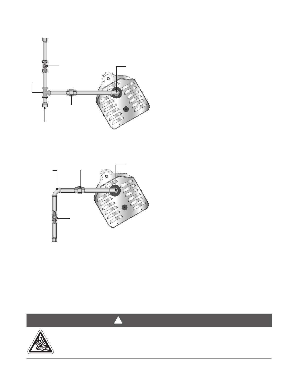
Figure 2.4 • Gas Connection - End View (shown installed from above)
NOTE: Do not exceed 14 inches W.C. to the
appliance. Use a regulator when gas supply
pressure exceeds 14 inches W.C.
Tee
Shut off valve /
inlet tap
(field supplied)
Ground
joint union
Drip leg / Sediment trap
(field supplied)
Elbow
Figure 2.5 • Gas Connection - End View (shown installed from below)
Elbow
Ground
joint union
Elbow
Shut off valve/
inlet tap
(field supplied)
To disconnect the gas:
1 Disconnect the power to the heater.
2 Turn off the gas supply to the heater and ”bleed” the gas line.
3 Using two wrenches, slowly loosen the fittings. Excessive torque on the manifold may misalign the
orifice.
4 Inspect the gas pipe. Replace if necessary.
5 Always cap off and leak check any open gas lines that are not in use.
Failure to disconnect the electricity to the heater before disconnecting the gas supply
may result in explosion, fire, property damage, injury or death.
WARNING
1515
Page 16
1717
2.0 Installation • Gas Supply • Leak Testing
!
!
!
!
DSC Series
Leak Testing
Use a soap solution or equivalent for leak testing. Leak testing solution must be non-corrosive, and be
rinsed off immediately after the leak test. Never test for leaks with an open flame. Failure to comply could
result in personal injury, property damage or death.
Always leak test the final gas assembly for gas leaks according to the procedures outlined in NFPA 54
and all local codes/or standards.
WARNING
Failure to install, operate or service this appliance in the approved manner may result in
property damage, injury or death. This heater must be installed and serviced by trained gas
installations and service personnel only.
The installation of this heater must conform with local building codes or, in the absence of
such codes, the National Fuel Code (NFPA 54).
!
WARNING
Testing for gas leaks with an open flame or other sources of ignition may lead to a fire or
explosion and cause serious injury or death. Test in accordance with NFPA or local codes.
For leak testing on pressures below ½ PSI
Before leak testing, close the field installed manual shut off valve shown in Figures 2.4 and 2.5 (pg.15) on
the supply line to isolate the gas valve from the pressure. NOTE: All factory installed gas connections
have passed an approved leak test.
For leak testing on pressures above ½ PSI
When leak testing with pressures above ½ PSI (14 inches W.C.) the unit’s gas controls must be isolated
from the supply pipe. Close the field installed manuals shut off valve, disconnect the supply line to the
unit, and temporarily cap the supply line for testing purposes.
!
WARNING
Gas pressures to the appliance controls must never exceed 14 inches W.C. (1/2 PSI).
Supply pressures greater than 14 inches W.C. can damage the controls, resulting in
personal injury, property damage, or death.
16
Page 17
DSC Series
!
2.0 Installation • Electrical Requirements
Electrical Requirements
WARNING
Incorrect or improper wiring may result in shock, injury or death. Field wiring to the heater
must be connected and grounded in accordance with national, state, provincial, local codes
and to the guidelines in this manual. Refer to the most current revisions to the ANSI/NFPA
70 Standard.
All field wiring to the patio heater must be done in accordance with the national, state, provincial, local
codes and the guidelines in this manual. In the United States, refer to the most current revisions to the
Electrical Code ANSI/NFPA 70 and in Canada refer to the most current revisions of the Canadian
Electrical Code CSA C22.1 Part 1. The unit must be electrically grounded according to these codes.
NOTICE
The power supply to the heater must be within +/-5% of the voltage rating as indicated on the rating plate
of the appliance. If input power does not meet these specifications, contact your utility company.
This patio heater system is designed to operate on an external 24VAC electrical system. Provide only
24VAC with a NEC Class 2 transformer to the control wires inside the controls compartment. Use at least
18 AWG Solid core thermostat type wire that has an adequate capacity and temperature rating for the
total load. Never locate the transformer inside the controls compartment.
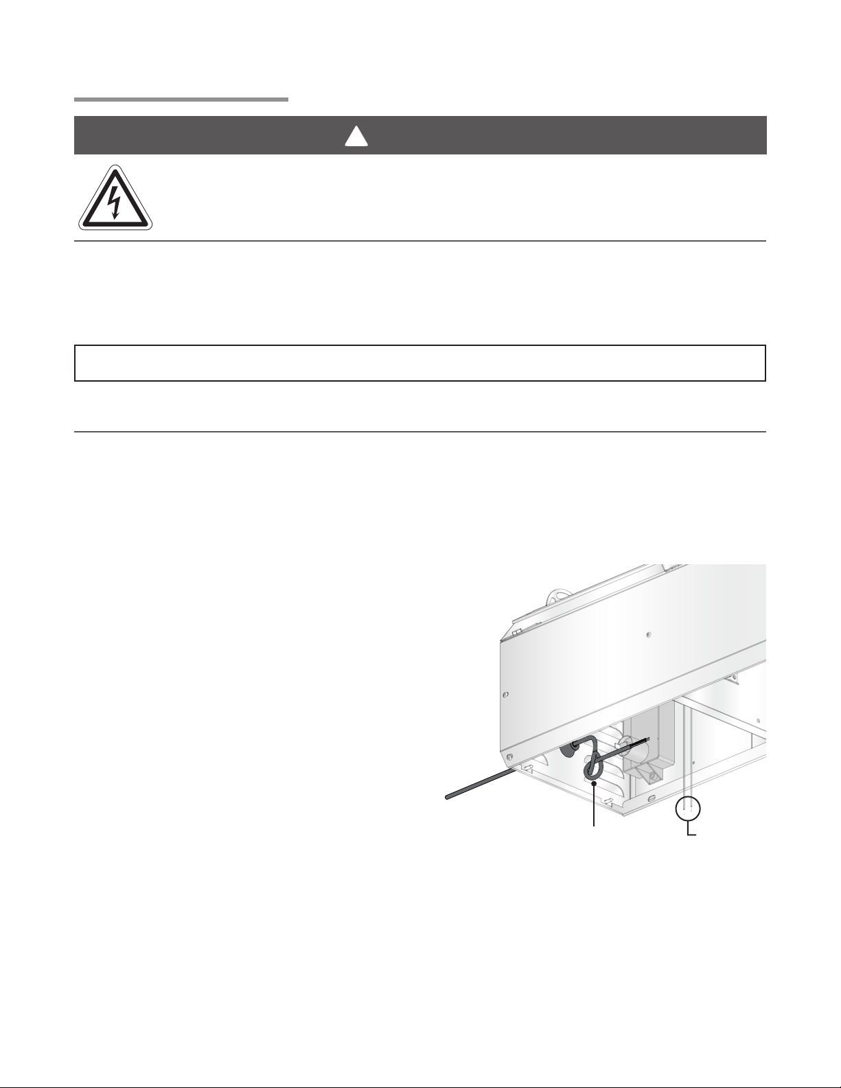
Installing the control wire
Each heater includes a rubber grommet to allow
for control wire to be brought into the unit with a
water resistant seal. Feed the control wire
through the grommet, piercing the rubber with
the wire. Ensure enough wire length is available
to make the proper connections. Tie the control
wire into a loose knot, as shown in Figure 2.6.
Ensure knot is loose enough to not cause any
damage to the wire. This will allow for a strain
relief for the connections to the heater.
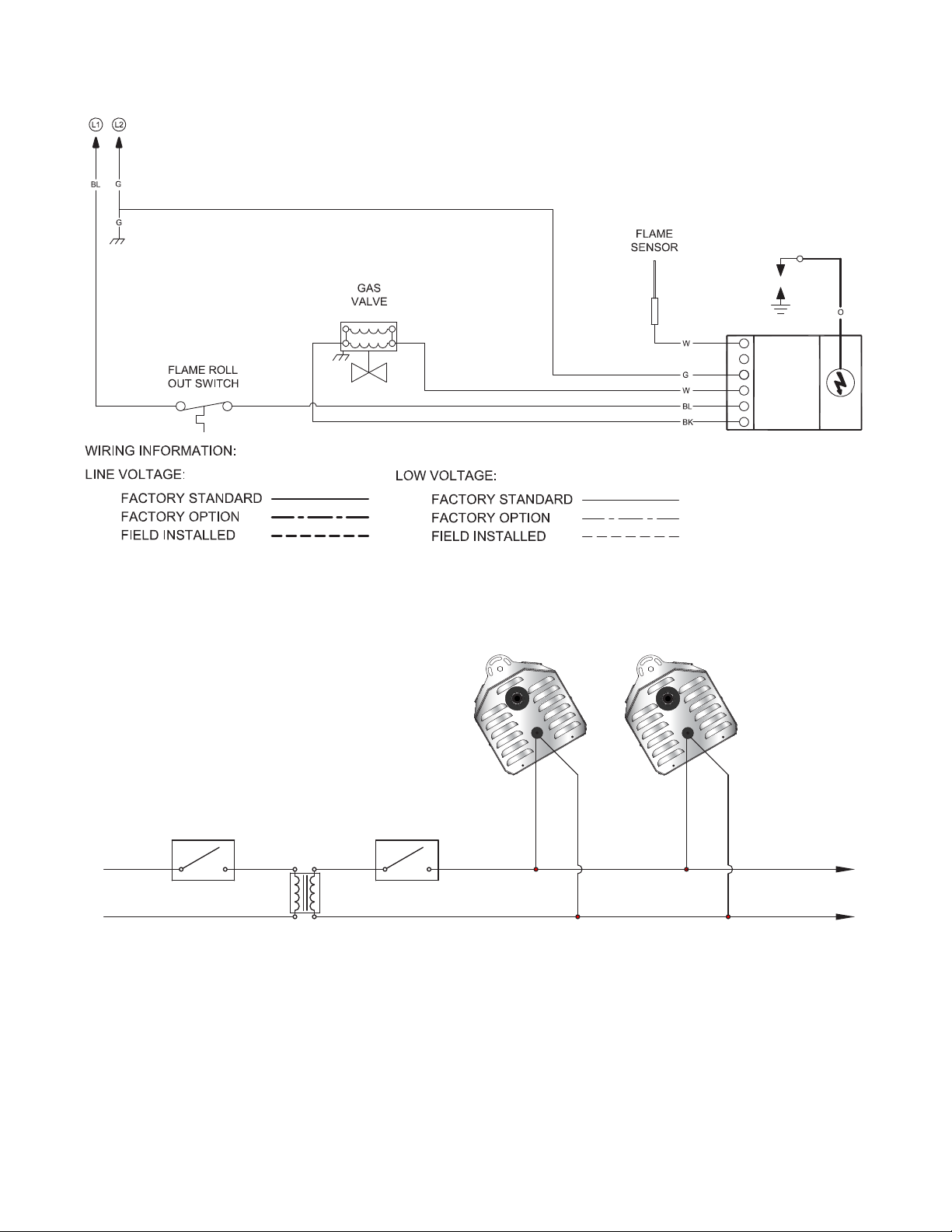
Wiring: From the control wire, connect the
24VAC to the blue wire (labeled “24VAC”) inside
the control compartment. Then connect the
Common from the control wire to the green wire
(labeled “Common”). See Fig 2.8, page 18.
Figure 2.6 • Control Wire Installation
Loose Knot in
Control Wire
Control Wire
Connections
Controls Operation
This patio heater was designed for use in an outdoor environment. Therefore, controlling the heater by
use of a thermostat may not be the best means of temperature control. In an outdoor application, the air
temperature may not increase and never satisfy the thermostat. The preferred control device when
operating this heater in an outdoor area is a switching or timer device.
In an application where there are several wind breaks or a partially enclosed area, a thermostat can be
used.
1717
Page 18
1919
3.0 Maintenance • Wiring Diagrams
Figure 2.7 • Internal Wiring Diagram
DSC Series
SENSE
GROUND
VALVE -
THERMOSTAT
VALVE +
IGNITION
MODULE
SPARK
Figure 2.8 • Field Wiring Diagram
Starting Amp Draw: 0.65 Amp
Running Amp Draw: 0.48 Amp
OPTIONAL
HOT
24
LOW VOLTAGE
SWITCH OR TIMER
LINE VOLTAGE
SWITCH OR TIMER
L1
120
VAC
L2
TRANSFORMER
VAC
EXTERNAL
Field Wiring:
1 24 VAC/20VA transformer (.8 Amp) per heater is required (supplied by installer).
2 Maintain electrical polarity when hooking up multiple heaters.
3 Allow heaters to be switched by zones for heating flexibility.
ADDITIONAL HEATERS
REQUIRE PROPERLY SIZED
24 VAC TRANSFORMER
4 Do not attempt to install transformer inside of heater.
18
Page 19
DSC Series
2.0 Installation • Ventilation
Ventilation
!
WARNING
Improper or insufficient ventilation may result in explosion, fire, health
problems, carbon monoxide poisoning or death. Vent enclosed spaces and
buildings according to national, state, provincial and local codes.
This infrared heater must be vented in accordance with national, state, provincial and local codes and the
guidelines in this manual. Refer to the latest edition of the ANSI Z223.1 (NFPA 54) Standard.
It is required that the upper levels of the space to be heated are properly ventilated to supply combustion
air to the heaters and to sufficiently dilute the products of combustion. It is also important to keep the flue
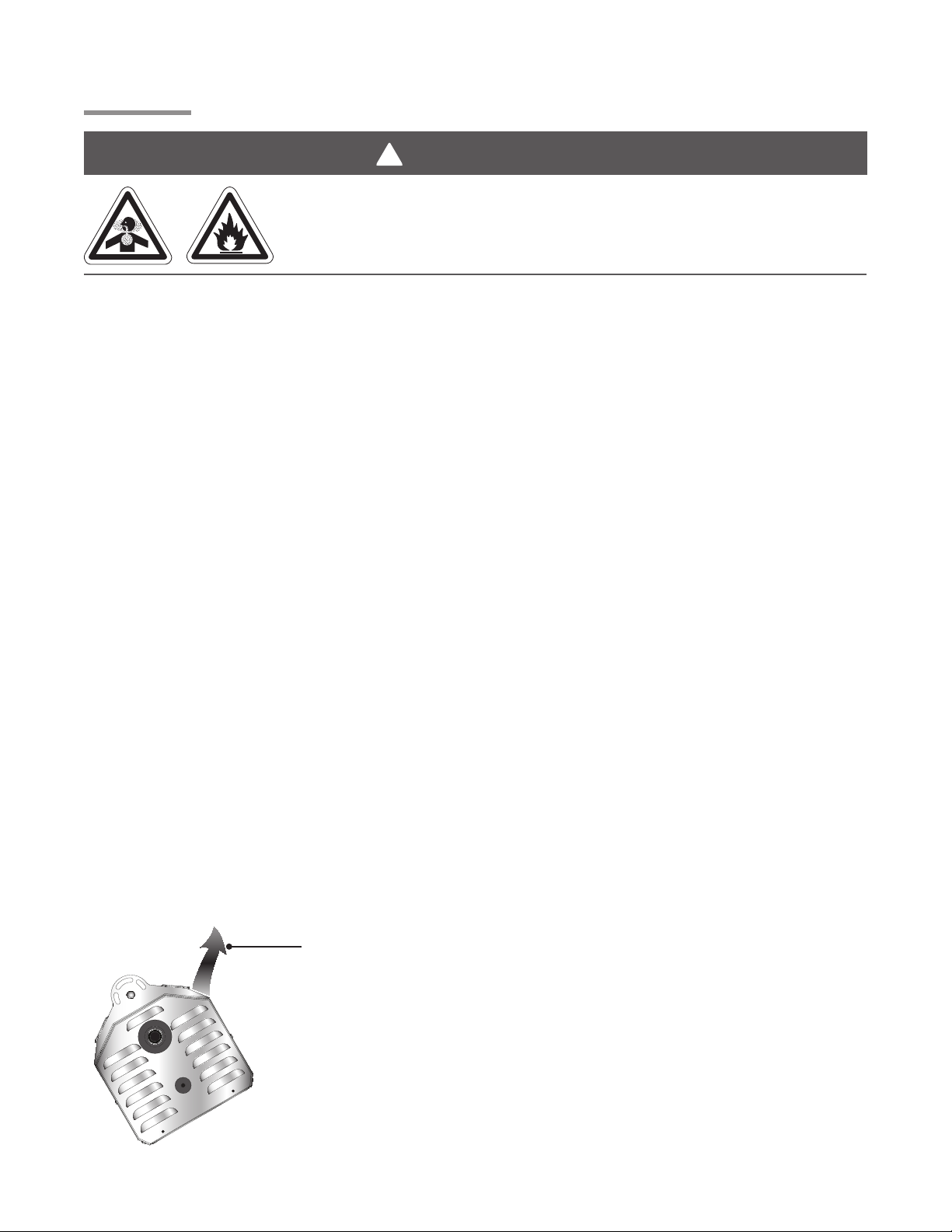
discharge area clear of gas piping and electrical wiring (see Figure 2.9).
Provisions must also be made to provide sufficient fresh air intake area and exhaust air outlet area.
Natural or mechanical means shall be provided to supply and exhaust at least 4 CFM/1,000 BTU/h of total
gas input of heaters installed. Exhaust openings for the removal of flue products must be above the level
of the heater(s).
Where insufficient air movement exists, induced air displacement is required. A balanced system is
essential to avoid negative building pressure which causes excessive infiltration, unfavorable drafts and
affects combustion efficiency.
Air displacement may be accomplished by either gravity or mechanical means. Mechanical exhausters
are preferred and typically mounted at high points on the roof over where stagnant air accumulates inside.
For a flat roof, considerations of prevailing winds, high and low pressure areas, and distribution of air
movement must be taken into consideration when locating exhausters.
Best air distribution is accomplished by using a number of small exhausters versus one large exhauster.
Provide a minimum of one square inch of inlet area per 1,000 BTU/h for combustion air supply. Inlet
opening in the building should be well distributed, located high on the wall and should direct incoming air
upward to dilute products of combustion while preventing drafts at lower levels. Inlets are typically 1 to 3
sq. ft.
In certain applications, local codes may require that mechanical exhaust systems be interlocked with the
heaters to enable both to function simultaneously or allow control of exhausters with a ceiling mounted
humidistat.
Figure 2.9 • Hot Flue Discharge
Discharge released from side
air channels. Keep area clear of
gas piping and electrical wiring.
1919
Page 20
2121
3.0 Operation • Sequence of Operation
!
DSC Series
3.0 Operation
WARNING
Improper operation of the heater may result in explosion, fire,
shock and carbon monoxide poisoning. Follow all guidelines and
warnings in this manual and national, state, provincial and local
codes. Always conduct safety checks before operating the heater.
Do not operate the heater in unsafe conditions.
Important! Before operating the heater, conduct the following safety procedures:
• Check for any possible gas leaks.
• Alert all persons about the hazards of high surface temperatures and to keep a safe distance away in
order to avoid burns and possible clothing ignition.
• Provide supervision when young children are in the area of the heater.
• Check to make sure clothing isn’t hung from the heater and that flammable materials are not
placed on or near the heater.
• Check that all guards or protective devices are in place and secure.
• Check control compartment, burners and circulating air passages for debris. If necessary, clean the
debris.
Sequence of Operation
Starting Circuit:
When voltage is applied to the controls connection, the ignition module sends power to the gas valve
while simultaneously sending spark to the igniter. The ignition time is 15 seconds. Once the flame on the
burner is established, the ignition module will continuously monitor the flame. The heater will continue to
run as long as there is 24VAC present in the call for heat. If the heater does not light on the first trial, the
heater will attempt two more ignitions prior to going into a lockout mode.
Running Circuit:
After ignition, the flame rod monitors the flame. As long as a flame is present, the valve is held open. If the
flame is lost, the control acts to close the valve within one second, and a new trial sequence identical to
that at start-up is initiated. If proof of flame is not established within the 15 second trial for ignition, the unit
will retry two additional times before entering lockout mode. If lockout occurs, the control can be reset by
briefly interrupting the power source.
20
Page 21
DSC Series
!
4.0 Maintenance
4.0 Maintenance
WARNING
Always wear clothing that protects the body and use protective
glasses when servicing the heater.
Electrical shock or explosion may occur when conducting
maintenance while the heater is connected to the power source
and gas supply. Disconnect power and gas supply to heater before servicing.
Burner malfunction may result in explosion or fire. Never operate the heater if there are any signs of
malfunction, excessive wear or damage. Call a professional for assistance.
Before each use:
• Check the gas supply line for any possible leaks or damage.
• Check heater elements for debris. Visually check burner flames.
• Keep the heated area clear and free of combustible materials, gasoline and flammable vapors and
liquids. Ensure there is no obstruction of the flow of combustion and ventilation.
Periodic maintenance:
• Clean the heater with cleaning agents suitable for the unit’s construction material (i.e., stainless
steel cleaner).
• Inspect the gas supply piping system for signs of corrosion or failure. Replace if necessary.
Before conducting maintenance on the heater disconnect the power and gas supply. When pressure
testing the gas supply piping system follow these guidelines:
• At a test pressure in excess of 1/2 psi (3.5 kPa) the heater and ball shutoff valve must be
disconnected from the gas supply piping system during any pressure testing of the system.
• At a test pressure equal to or less than 1/2 psi (3.5 kPa) the heater must be isolated from the gas
supply piping system by closing it’s individual manual shutoff valve during any pressure testing of the
gas supply piping system.
Cleaning the main burner:
NOTICE
Cleaning the heater elements with high pressure air may cause damage to the elements and equipment
failure. Do not blow out heating elements with high pressure air.
1 Use an air hose to blow any accumulated dust and/or dirt off the heater. Air hose pressure
should not exceed 30 psi.
2 Pass the air hose over the entire exposed area of the ceramic. A distance of 2’ to 4’ from the unit is
recommended.
3 Place the air hose outlet into the venturi tube and allow the air to flow for approximately one minute.
During long periods of non-usage, remove or cover heater with a polyethylene bag and shut off gas
supply. If further service to the heater is desired, contact your representative or the factory.
2121
Page 22
2323
4.0 Maintenance • Service Access Panel Removal
DSC Series
Service Access Panel Removal
Before removing the service access panel on appliance, allow the unit to cool completely before servicing.
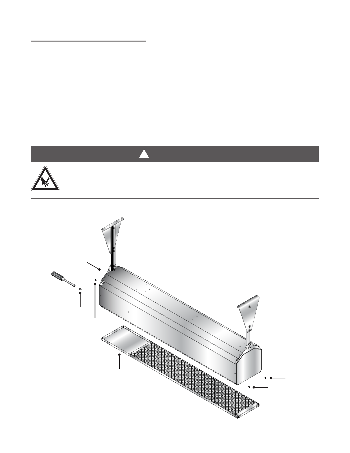
To remove the service access panel a ¼” nut driver will be needed.
1 Remove the two ¼” screws on the control end of the unit first while holding the panel in place (see
Figure 4.1).
2 Proceed to the opposite side of the unit while holding the panel in place and remove the last two ¼”
screws.
3 Slowly allow the face to rotate open towards the component side of unit and remove service access
panel.
Failure to support the service access panel during removal can result in damage to the piece and or
uncontrolled dropping of the panel possibly causing injury.
!
WARNING
Crown Verity makes every possible effort to remove sharp edges, however, caution should be
taken to avoid contact with potentially sharp edges on the heater housing. Sharp edges may
cut, resulting in personal injury.
Figure 4.1 • Service Access Panel Removal
Control End
1/4” Screw
1/4” Screw
Service
Access Panel
1/4” Screw
1/4” Screw
22
Page 23

DSC Series
Chart 4.1 • Troubleshooting Guide
Symptom Possible Cause Corrective Action
Burning of gas-air mixture
inside plenum (flashback).
Rumbling noise present.
Delayed ignition. • Electrode out of specification.
Low ceramic surface
temperature or excessive
rollout.
Control system overheating. • Heater not mounted correctly.
• Heater mounted at incorrect angle.
• Excessive drafts.
• Gas leaking at orifice.
• Separation of ceramic grids.
• Ceramic grids cracked.
• Low gas pressure.
• Partially blocked orifice.
• Improper orifice size.
• Incorrect gas.
• Dirty or plugged burner ceramics.
• Partially blocked orifice.
• Low inlet gas pressure.
• High or low manifold gas pressure.
• Foreign matter in venturi tube.
• Excessive dark spots on burner.
• Gas supply piping too small.
• Incorrect gas.
• Heater mounted too close to
ceiling.
4.0 Maintenance • Troubleshooting Guide
• Mount at a 0˚- 30˚angle from horizontal.
• Relocate heater or shield from draft.
• Check with leak detector solution.
• Replace burner.
• Replace burner.
• See ignition system insert.
• See Section 2.0, Gas Supply.
• Clean or replace gas orifice.
• Consult distributor.
• See unit rating plate.
• See periodic maintenance instructions.
• Remove and clean.
• See Section 2.0, Gas Supply.
• Adjust main valve regulator as specified.
• See periodic maintenance instructions.
• See periodic maintenance instructions.
• Increase inlet pressure or replace piping.
• See unit nameplate.
• Mounting angle 0°- 30°. Level left to right.
• Observe clearance to combustibles.
Gas odor. • Loose pipe connection. • Check connections. Tighten as necessary.
Heater cycles repeatedly. • Heater located in drafty area.
• Low gas pressure.
• Thermostat located in drafty area.
• Defective flame electrode or circuit
board.
No spark; no ignition. • Lack of 24V incoming voltage.
• Open high voltage wire.
• Improper electrode gap.
• Loose or open wire connection.
• Poor or no equipment ground.
• Unit in “safety lockout” mode.
• Defective control module.
Heater lights, and “locks
out” after approximately 10
seconds.
Spark is present. No main
gas operation. Unit “locks
out”.
Heater will not shut off. • Defective thermostat or wiring.
• Poor or no equipment ground.
• Polarity is reversed.
• Low gas pressure.
• Electrode not sensing.
• Heater mounted at incorrect angle.
• Defective control module.
• Gas valve in “OFF” position.
• Defective gas valve.
• Defective control module.
• Gas valve stuck or open.
• High gas pressure.
• Relocate or shield from draft.
• See Section 2.0, Gas Supply.
• Relocate thermostat.
• Replace electrode and/or circuit board.
• Check power supply.
• Isolate and check resistance, replace if
open.
• See Ignition System specifications.
• Check all wires, tighten or replace.
• Check all connections, provide positive
earth ground.
• Interrupt power source, repeat trial
for ignition.
• Replace circuit board.
• Check all connections, provide positive
earth ground.
• Correct wiring.
• See Section 2.0, Gas Supply.
• Relocate or replace if electrode is defective.
• Mounting angle 0˚- 30˚.
• Replace circuit board.
• Turn to “ON” position.
• Isolate and check for resistance, replace
if reading open.
• Replace circuit board.
• Replace thermostat or repair wiring.
• Replace gas valve.
• See Section 2.0, Gas Supply.
2323
Page 24

2525
4.0 Maintenance • Maintenance Log
DSC Series
Maintenance Log
Date Maintenance Performed Replacement Parts Required
24
Page 25

DSC Series
Notes
4.0 Maintenance • Notes
2525
Page 26
2727
5.0 Parts • Heater Components
5.0 Parts
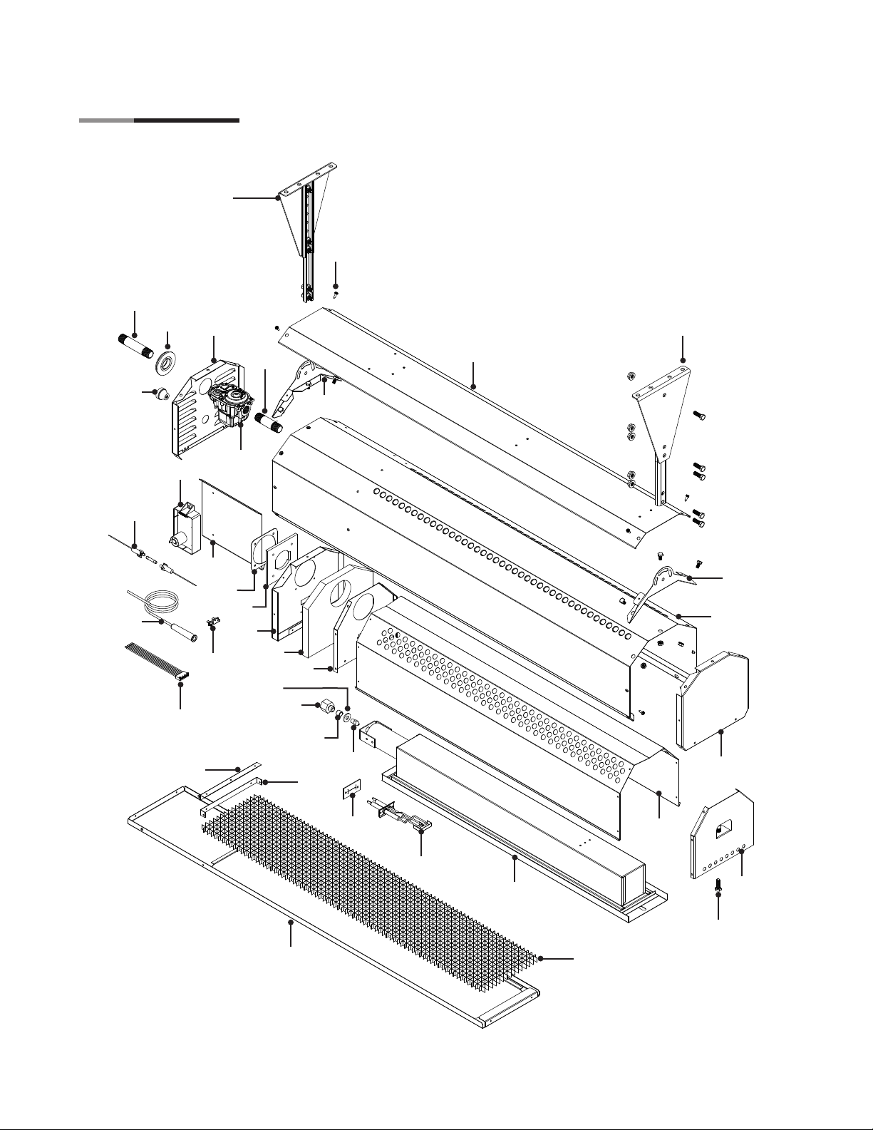
Figure 5.1 • Heater Components
1198, 1298
1143
1147
1104
DSC Series
1124
1198, 1298
1137
1134
1155
1151
1152
1113
1153
1120
1157
1140,
1141
1121
1172
1142
1122
1149
1148
1174
1146
1197
1112
1144
1110
1197
1101
1106
1105
1154
1150
26
1170
1117
1178
1123
1111
Page 27

DSC Series
5.0 Parts • Parts List
Chart 5.1 • Parts List
Part No. Description
PH-1101 Exterior Casing
PH-1104 Control End Panel - A
PH-1105 Service Access Panel
PH-1106 End Panel
PH-1110 Rain Guard
PH-1111 Egg Crate
PH-1112 Egg Crate Locator
PH-1113 Egg Crate Access Bracket
PH-1117 Reflector
PH-1120 Venturi Gasket Holder
PH-1121 Venturi Gasket
PH-1122 Insulation
PH-1123 5/16”-18x3/4” S.S. Hex Head Screw
PH-1124 1/4” x 1/2” Shoulder Sheet Metal Screw
PH-1134 In-Line Fuse
PH-1137 Thermostat Wire Grommet
PH-1140 Gas Valve (Natural Gas)
PH-1141 Gas Valve (Propane)
PH-1142 3“ Gas Pipe
PH-1143 4” Gas Pipe
PH-1144 Gas Orifice (Specify Model)
PH-1146 Coupler (Natural Gas Only)
PH-1147 Rubber Inlet Grommet
PH-1148 1/2” to 1/8” NPT Adapter
PH-1149 Air Metering Washer (Natural Gas Only)
PH-1150 Electrode
PH-1151 Circuit Board
PH-1152 Circuit Board Wiring Harness
PH-1153 Component Panel
PH-1154 Electrode Gasket
PH-1155 High Voltage Wire w/ Boot
PH-1157 Thermal Fuse
PH-1170 Burner Assembly
PH-1172 Divider Panel
PH-1174 Reflector End - Ignition Side
PH-1178 Reflector End - Burner Support w/ Nutsert
PH-1197 Hanging Bracket Qty. 2
PH-1198 Wall Mounting Bracket Assembly (Black) Qty. 2 (Optional)
PH-1298 Wall Mounting Bracket (Stainless Steel) Qty. 2 (Optional)
To order replacement parts call Crown Verity at: 1-888-505-7240 or visit our website: www.crownveritystore.com
2727
Page 28

6.0 Limited Warranty
DSC Series
6.0 Limited Warranty
One-Year Limited Warranty. Patio Heaters covered in this manual, are warranted by Crown Verity Inc. to the original user
against defects in workmanship or materials under normal use for one year after date of purchase. Any part which is
determined to be defective in material or workmanship and returned to an authorized service location, as Crown Verity Inc.
designates, shipping costs prepaid, will be, as the exclusive remedy, repaired or replaced at Crown Verity Incorporated’s
option. For limited warranty claim procedures, see PROMPT DISPOSITION below. This limited warranty gives purchasers
specific legal rights which vary from jurisdiction to jurisdiction.
Additional Limited Warranty. In addition to the above mentioned one-year warranty, Crown Verity Inc. warrants the original
purchaser an additional four-year extension on the ceramic burner. This extension excludes electrical/purchased components.
General Conditions. The Company will not be responsible for labor charges for the analysis of a defective condition of the
heater or for the installation of replacement parts. The warranties provided herein will not apply if the input of the heater
exceeds the rated input at time of manufacturing or if the heater in the judgment of the Company has been subjected to
misuse, excessive dust, improper conversion, negligence, accident, corrosive atmospheres, excessive thermal shock,
excessive vibration, physical damage to the heater, alterations by unauthorized service personnel, operation contrary to the
Company’s instructions or if the serial number has been altered, defaced, or removed. The Company shall not be liable for
any default or delay in the performance of these warranties caused by contingency beyond its control, including war,
government restriction or restraints, strikes, fire, flood, short or reduced supply of raw materials, or parts.
Limitation of Liability. To the extent allowable under applicable law, Crown Verity Incorporated’s liability for consequential
and incidental damages is expressly disclaimed. Crown Verity Incorporated’s liability in all events is limited to and shall not
exceed the purchase price paid.
Warranty Disclaimer. Crown Verity Inc. has made a diligent effort to provide product information and illustrate the products in
this literature accurately; however, such information and illustrations are for the sole purpose of identification, and do not
express or imply a warranty that the products are merchantable, or fit for a particular purpose, or that the products will
necessarily conform to the illustrations or descriptions. Except as provided below, no warranty or affirmation of fact, expressed
or implied, other than as stated in the “LIMITED WARRANTY” above is made or authorized by Crown Verity Inc.
Product Suitability. Many jurisdictions have codes and regulations governing sales, construction, installation, and/or use of
products for certain purposes, which may vary from those in neighboring areas. While Crown Verity Inc. attempts to assure
that its products comply with as many codes, it cannot guarantee compliance, and cannot be responsible for how the product
is installed or used. Before purchase and use of a product, review the product applications, and all applicable national and
local codes and regulations, and be sure that the product, installation, and use will comply with them.
Certain aspects of disclaimers are not applicable to consumer products: e.g., (a) some jurisdictions do not allow the exclusion
or limitation of incidental or consequential damages, so the above limitation or exclusion may not apply to you: (b) also, some
jurisdictions do not allow a limitation on how long an implied warranty lasts, consequently the above limitation may not apply to
you: and (c) by law, during the period of this limited warranty, any implied warranties of implied merchantability or fitness for a
particular purpose applicable to consumer products purchased by consumers, may not be excluded or otherwise disclaimed.
Prompt Disposition. Crown Verity Inc. will make a good faith effort for prompt correction or other adjustment with respect to
any product which proves to be defective within limited warranty. For any product believed to be defective within limited
warranty, first write or call dealer from whom the product was purchased. Dealer will give additional directions. If unable to
resolve satisfactorily, write to Crown Verity Inc. at address below, giving dealer’s name, address, date and number of dealer’s
invoice, and describe the nature of the defect. Title and risk of loss pass to buyer on delivery to common carrier. If product was
damaged in transit to you, file claim with carrier.
C R O W N V E R I T Y I N C .
37 Adams Boulevard, Brantford, Ontario, Canada N3S 7V8
tel 519.751.1800 or 888.505.7240 fax 519.751.1802 e-mail [email protected] web www.crownverity.com
28
 Loading...