

Page 1
CTs 600
Obtaining Other Language Versions:
To obtain information in another language about the use of this product, please contact your
local Crown Distributor. If you need assistance locating your local distributor, please contact Crown at 574-294-8000.
This manual does not include all of the details of design, production, or variations of the equipment. Nor does it cover every possible situa-
tion which may arise during installation, operation or maintenance.
The information provided in this manual was deemed accurate as of the publication date. However, updates to this information may have
occurred. To obtain the latest version of this manual, please visit the Crown website at www.crownaudio.com.
Trademark Notice:
Com-Tech, BCA, Crown, Crown Audio, Amcron and Multi -Mode are registered trademarks of Crown Interna tional.
IQwic, PIP and PIP2 are trademarks of Crown International. Other trademarks are the property of their respective owners.
© 2007 by Crown Audio®, Inc. 1718 W. Mishawaka Rd., Elkhart, Indiana 46517-9439 U.S.A. Telephone: 574-294-8000
137000-4A
9/07
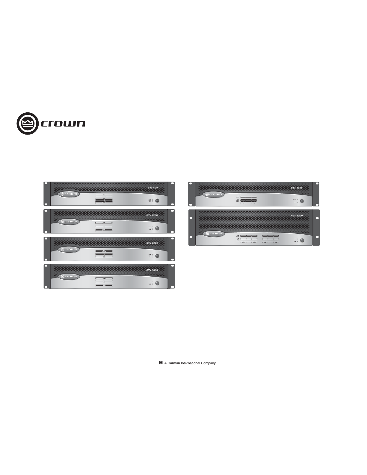
CTs Series Operation Manual
CTs 1200
CTs 2000
CTs 3000
Page 3: 2-channel models
Page 31: Multi-channel models
CTs 8200
CTs 4200
Page 2
Operation Manual
CTs Power Amplifiers
page 2
1) Read these instructions.
2) Keep these instructions.
3) Heed all warnings.
4) Follow all instructions.
5) Do not use this apparatus near water.
6) Clean only with a dry clot h.
7) Do not block any ventilation openings. Install in accordance
with the manufacturer’s instructions.
8) Do not install near any heat sour ces such as radiators, heat registers, stoves, or other apparatus (including amplifiers) that
produce heat.
9) Do not defeat the safety purpose of the polarized or groundingtype plug. A polarized plug has two bla des with one wider than
the other. A grounding-type plug has two blades and a third
grounding prong. The wide blade or the third prong is provided
for your safety. If the provided plug does not fit i nto your outlet,
consult an electrician for replacement of the obsolete outlet.
10) Protect the power cord from being w alked on or pinched, particularly at plugs, convenience receptacles, and the point where
they exit from the apparatus.
11) Only use attachments/accessories specified by the manufacturer.
12) Use only with a cart, stand, tripod, bracket, or table specified by
the manufacturer, or sold with the apparatus. When a cart is
used, use caution when moving the cart/apparatus combination
to avoid injury from tip-over.
13) Unplug this apparatus during lightning storms or when unused
for long periods of time.
14) Refer all servicing to qualified service personnel. Servicing is
required when the apparatus has been damaged in any way,
such as power-supply cord or plug is da maged, liquid has been
spilled or objects have fallen into the apparatus, the apparatus
has been exposed to rain or moisture, does not operate normally, or has been dropped.
15) Use the mains plug to disconnect the apparatus from the mains.
16) WARNING: TO REDUCE THE RISK OF FIRE OR ELECTRIC
SHOCK, DO NOT EXPOSE THIS APPARATUS TO RAIN OR
MOISTURE.
17) DO NOT EXPOSE THIS EQUIPMENT TO DRIPPING OR
SPLASHING AND ENSURE THAT NO OBJECTS FILLED WITH
LIQUIDS, SUCH AS VASES, ARE PLACED ON THE EQUIPMENT.
18) THE MAINS PLUG OF THE POWER SUPPLY CORD SHALL
REMAIN READILY OPERABLE.
TO PREVENT ELECTRIC SHOCK DO NOT REMOVE TOP OR
BOTTOM COVERS. NO USER SERVICEABL E PARTS INSIDE.
REFER SERVICING TO QUALIFIED SERVICE PERSONNEL.
À PRÉVENIR LE CHOC ÉLECTRIQUE N’ENLEVE Z PAS LES
COUVERCLES. IL N’Y A PAS DES PARTIES SERVICEABLE À
L’INTÉRIEUR. TOUS REPARATIONS DOIT ETRE FAIRE PAR
PERSONNEL QUALIFIÉ SEULMENT.
PARA PREVENIR UN CHOQUE ELÉCTRICO, NO RETIRE LAS
CUBIERTAS SUPERIOR O INFERIOR. NO EXISTEN PARTES
QUE PUEDAN SER REPARADAS POR EL USUARIO AL INTERIOR. REMITA EL SERVICICO AL PERSONAL TÉCHNICAL
CALIFICADO.
TO COMPLETELY DISCONNECT THIS EQUIPMENT FROM
THE AC MAINS, DISCONNECT THE POWER SUPPLY CORD
PLUG FROM THE AC RECEPTACLE. THE MAINS PLUG OF
THE POWER SUPPLY CORD SHALL REMAIN READILY
OPERABLE.
POUR DÉMONTER COMPLÈTEMENT L'ÉQUIPEMENT DE
L'ALIMENTATION GÉNÉRALE, DÉMONTER LE CÂBLE D'ALIMENTATION DE SON RÉCEPTACLE. LA PRISE D'ALIMENTATION RESTERA AISÉMENT FONCTIONNELLE.
PARA DESCONECTAR COMPLETAMENTE EL EQUIPO DEL
SUMINSTRO ELECTRICO, DESCONECTE EL CAB LE DE ALIMENTACION DE LA TOMA DE CA. LAS PATAS DEL CONECTOR DEL CABLE DE ALIMENTACIÓN DEBERAN
MANTENERSE EN BUEN ESTADO.
WATCH FOR THESE SYMBOLS:
The lightning bolt triangle is used to alert the user to the risk
of electric shock.
The exclamation point triangle is used to alert the user to
important operating or maintenance instructions.
REGARDEZ CES SYMBOLES
La triangle avec le sigle ‘’foudre’’ est employée pour alerter
l'utilisateur au risque de décharge électrique. Le triangle avec
un point d'exclamation est employée pour alerter l'utilisateur
d’instruction importantes pour lors opérations de maintenance.
ATENCION CON ESTOS SÍMBOLOS
El triángulo con el símbolo de rayo eléctrico es usado para
alertar al usuario de el riesgo de un choque eléctrico.
El triángulo con el signo de a dmiración es usado para alertar
al usuario de instrucciones imp ortantes de operación o mantenimiento.
Important Safety Instructions
FCC COMPLIANCE NOTICE
This device complies with part 15 of the FCC rules. Operation is subject to the following
two conditions: (1) This device may not cause harmful interference, and (2) this device
must accept any interference received, including interference that may caus e undesired
operation.
CAUTION: Changes or modifications not expressly approved by the party responsible for
compliance could void the user’s authority to operate the equipment.
NOTE: This equipment has been tested and found to comply with the limits for a Class B
or Class A digital device (depending on the model), pursuant to part 15 of the FCC Rules.
These limits are designed to provide reasonable protection against harmful interference in
a residential installation. This equipment generates, uses, and can radiate radio frequency
energy and, if not installed and used in accordance with the instruction manual, may
cause harmful interference to radio communications. However, there is no guarantee that
interference will not occur in a particular installation. If this equipment does cause harmful interference to radio or television reception, which can be determined by turning the
equipment off and on, the user is encouraged to try to correct the interference by one or
more of the following measures:
• Reorient or relocate the receiving antenna.
• Increase the separation between the equipment and receiver.
• Connect the equipment into an outlet on a circuit different from that to which the
receiver is connected.
• Consult the dealer or an experienced radio/TV technician for help.
IMPORTANT
CTs Series amplifiers require Class 2 output wiring.
Les amplificateurs de série de CTs exigent des câbles de sortie de
classe 2.
CTs-Reihe-Verstärker verlangen Klasse die 2 Produktionsverdrahtung.
Los amplificadores de la Serie CTs requieren de un cableado de
salida Clase 2.
MAGNETIC FIELD
CAUTION! Do not locate sensitive high-gain equipment such as
preamplifiers or tape decks directly above or below the unit.
Because this amplifier has a high power density, it has a strong
magnetic field which can induce hum into unshielded devices that
are located nearby. The field is strongest just above and below the
unit.
If an equipment rack is used, we recommend locating the amplifier(s) in the bottom of the rack and the preamplifier or other sensitive equipment at the top.
Instrucciones de Seguridad Importantes
Importantes Instructions de Sécurité
Wichtige Sicherheitsinstruktionen
Page 3
page 3
CTs Power Amplifiers
Operation Manual
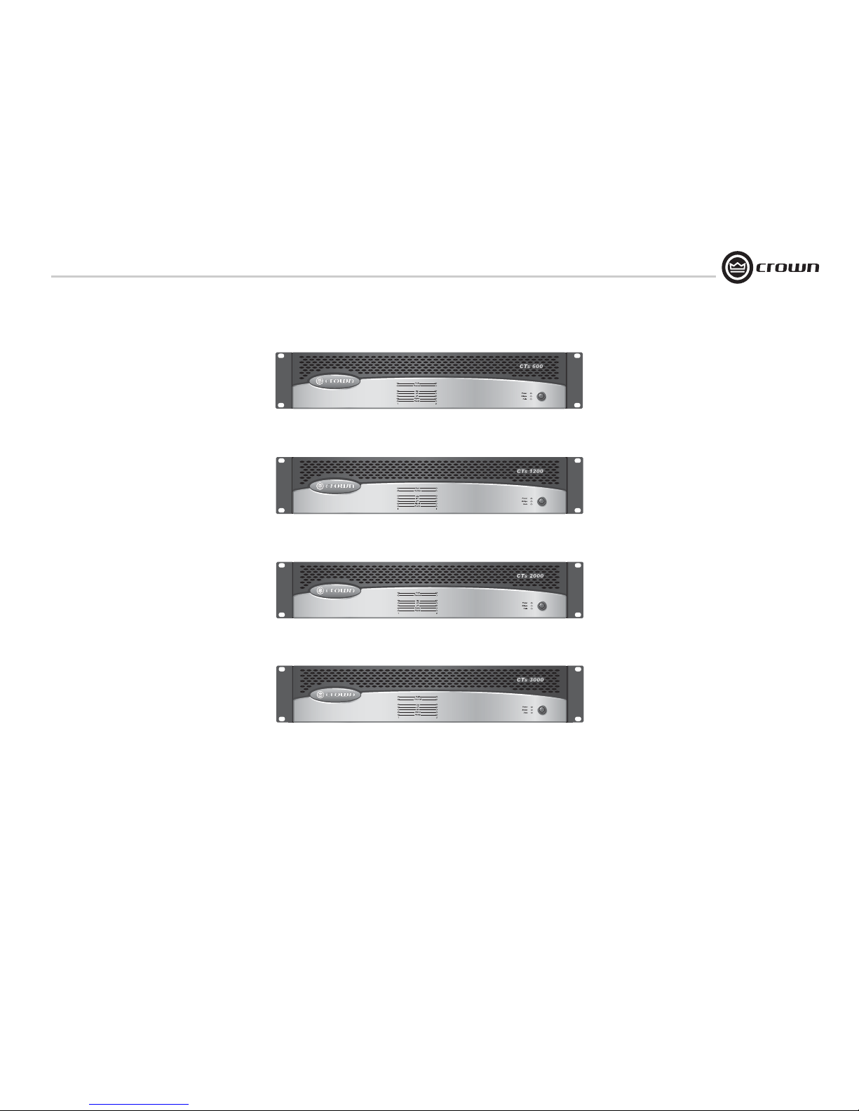
CTs 600
CTs 2-Channel Series
CTs 1200
CTs 2000
CTs 3000
Page 4

Operation Manual
CTs Power Amplifiers
page 4
THIS PAGE INTENTIONALLY LEFT BLANK
Page 5

page 5
CTs Power Amplifiers
Operation Manual
DECLARATION of CONFORMITY
Crown Audio, Inc.
Sue Whitfield
574-294-8289
[email protected]
European Representative's Name and Address:
David Budge
10 Harvest Close
Yateley GU46 6YS
United Kingdom
Equipment Type: Commercial Audio Power Amplifiers
Family Name: CTs
Model Names: CTs 3000, CTs 2000, CTs 1200, CTs 600
EMC Standards:
EN 55103-1:1997 Electromagnetic Compatibility - Product Family Standard for Audio, Video, Audio-Visual and Entertainment Lighting Control Apparatus for Professional Use, Part 1: Emissions
EN 55103-1:1997 Magnetic Field Emissions-Annex A @ 10 cm and 1 M
EN 61000-3-2:1995+A14:2000 Limits for Harmonic Current Emissions (equipment input current ≤16A per phase)
EN 61000-3-3:1995 Limitation of Voltage Fluctuations and Flicker in Low-Voltage Supply Systems Rated Current ≤16A
EN 55022:2003 Limits and Methods of Measurement of Radio Disturbance Characteristics of ITE: Radiated, Class B Limits; Conducted, Class B
EN 55103-2:1997 Electromagnetic Compatibility - Product Family Standard for Audio, Video, Audio-Visual and Entertainment Lighting Control Apparatus for Professional Use, Part 2: Immunity
EN 61000-4-2:2003 Electrostatic Discharge Immunity (Environment E2-Criteria B, 4k V Contact, 8k V Air Discharge)
EN 61000-4-3:2003 Radiated, Radio-Frequency, Electromagnetic Immunity (Environment E2, criteria A)
EN 61000-4-4:2005 Electrical Fast Transient/Burst Immunity (Criteria B)
EN 61000-4-5:2001 Surge Immunity (Criteria B)
EN 61000-4-6:1996 Immunity to Conducted Disturbances Induced by Radio-Frequency Fields (Criteria A)
EN 61000-4-11:2004 Voltage Dips, Short Interruptions and Voltage Variation
Safety Standard:
EN 60065: 1998 Safety Requirements - Audio Video and Similar Electronic Apparatus
I certify that the product id entified above conforms to the requirements of the EMC Council Directive 89/336/EEC as amended by 92/31/EEC, and the Low Voltage Directive 73/23/EES as amended by 93/68/EEC.
Larry Coburn
Signed
Title: Senior Vice President of Manufacturing
Date of Issue: March 1, 2002
ISSUED BY: Crown Audio, Inc.
1718 W. Mishawaka Road
Elkhart, Indiana 46517 U.S.A.
Due to line current harmonics, we recommend that you contact your supply authority before connection.
FOR COMPLIANCE QUESTIONS ONLY:
Page 6

Operation Manual
CTs Power Amplifiers
page 6
Important Safety Instructions .......................................................... 2
CTs 2-Channel Models ............................3
Declaration of Conformity .............................................................. 5
1 Welcome ...................................................... 8
1.1 Features ............................................................................. 8
2 How to Use This Manual .................................... 9
3 Setup ........................................................... 10
3.1 Unpack Your Amplifier .......................................................10
3.2 Install Your Amplifier ......................................................... 10
3.3 Ensure Proper Cooling ....................................................... 10
3.4 Choose Input Wire and Connectors .................................... 11
3.5 Choose Output Wire and Connectors ................................. 11
3.6 Wire Your System .............................................................. 12
3.6.1 Dual 8/4/2 Mode ....................................................... 12
3.6.2 Bridge-Mono 16/8/4 Mode ........................................ 12
3.6.3 Dual 70V/100V Mode ................................................ 13
3.6.4 Bridge-Mono 140V/200V Mode ................................ 13
3.6.5 Dual Mode with “Y” Input .......................................... 14
3.7 Connect to AC Mains .........................................................15
3.8 Startup Procedure .............................................................. 15
4 Operation ...................................................... 15
4.1 Precautions ........................................................................15
4.2 Front Panel Controls and Indicators ................................... 16
4.3 Back Panel Controls and Connectors ................................. 17
5 Advanced Features and Options ...........................18
5.1 Protection Systems ............................................................18
5.1.1 Thermal Level Control (TLC) .....................................18
5.1.2 Junction Temperature Simulation (JTS) .....................18
5.1.3 Fault ..........................................................................18
5.1.4 High-Pass Filters ......................................................18
5.1.5 Low-Pass Filters .......................................................18
5.1.6 AC Under/Over Voltage Protection ............................18
5.1.7 Circuit Breaker ..........................................................18
5.1.8 DC Output Servo .......................................................18
5.1.9 Inrush Limiting ..........................................................18
5.1.10 Variable-speed Fans ................................................18
5.2 Advanced Features .............................................................18
5.2.1 Switching Power Supply ...........................................18
5.2.2 Input Compressor .....................................................18
5.2.3 Sleep Circuit ..............................................................18
5.2.4 Input Sensitivity Switches .........................................19
5.3 Options ..............................................................................19
5.3.1 Nominal Attenuation Settings ....................................20
6 Troubleshooting ...............................................21
7 Specifications .................................................23
8 AC Power Draw and Thermal Dissipation .................27
(Continued on next page)
Table of Contents
Page 7

page 7
CTs Power Amplifiers
Operation Manual
CTs Multi-Channel Models
......................31
Declaration of Conformity ...........................................................32
1 Welcome .................................................... 33
1.1 Features .......................................................................... 33
2 How to Use This Manual .................................. 33
3 Setup ........................................................ 34
3.1 Unpack Your Amplifier .................................................... 34
3.2 Install Your Amplifier ......................................................34
3.3 Ensure Proper Cooling .................................................... 34
3.4 Choose Input Wire and Connectors ................................ 35
3.5 Choose Output Wire and Connectors .............................. 35
3.6 Wire Your System ...........................................................36
3.6.1 Dual 8/4 Mode ....................................................... 36
3.6.2 Dual 70V Mode ...................................................... 36
3.6.3 Bridge-Mono 16/8 Mode ....................................... 37
3.6.4 Bridge-Mono 100V Mode ...................................... 37
3.7 Connect to AC Mains ...................................................... 38
3.8 Startup Procedure ...........................................................38
4 Operation ................................................... 39
4.1 Precautions ..................................................................... 39
4.2 Front Panel Controls and Indicators ............................... 40
4.3 Back Panel Controls and Connectors ..............................41
5 Advanced Features and Options ......................... 42
5.1 Protection Systems .........................................................42
5.1.1 Thermal Level Control (TLC) .................................. 42
5.1.2 Fault .......................................................................42
5.1.3 Fault Isolation Topology (FIT) ................................ 42
5.1.4 35-Hz High-Pass Filter ..........................................42
5.1.5 AC Under-/Over-Voltage Protection .......................42
5.1.6 Power Fuse ............................................................42
5.1.7 Inrush Limiting ...................................................... 42
5.1.8 Variable-speed Fans ..............................................42
5.2 Advanced Features ..........................................................42
5.2.1Switching Power Supply .........................................42
5.2.2 Mode Switch .......................................................... 42
5.2.3 Bridge Mode Indicator ...........................................42
5.2.4 Channel Level Control ...........................................43
5.3 Options ........................................................................... 44
5.3.1 Control Modules .................................................... 44
5.3.2 Input Sensitivity .....................................................44
6 Troubleshooting ........................................... 45
7 Specifications .............................................. 47
8 AC Power Draw and Thermal Dissipation .............. 51
CTs 2-Channel and Multi-Channel Models
9 Service ...................................................... 53
9.1. International and Canada Service ...................................53
9.2 US Service ......................................................................53
9.2.1 Service at a US Service Center ...............................53
9.2.2 Factory Service ...................................................... 53
9.2.3 Factory Service Shipping Instructions..................... 53
9.2.4 Packing Instructions ...............................................53
9.2.5 Estimate Approval...................................................53
9.2.6 Payment of Non-Warranty Repairs.......................... 53
10 Warranty ................................................... 54
Factory Service Information Form ...............................................57
Product Registration Form........................................................... 59
Table of Contents
Page 8
Operation Manual
CTs Power Amplifiers
page 8
1 Welcome
Building on the foundation of the Com-Tech®
Series, the Crown
®
CTs Series offers new flexibility and value for installed sound. The ComTech Series was the first to offer independent
selection of high- and low-impedance operation for a specific channel, and CTs Series
amplifiers continue that tradition, with power
levels and features carefully chosen to perfectly
integrate into fixed install design requirements.
Modern power amplifiers are sophisticated
pieces of engineering capable of producing
extremely high power levels. They must be
treated with respect and correctly installed if
they are to provide the many years of reliable
service for which they were designed.
In addition, CTs Series amplifiers include a
number of features which require some explanation before they can be used to their maximum advantage.
Please take the time to study this manual so
that you can obtain the best possible service
from your amplifier.
1.1 Features
• Switching Power Supply for reduced
weight.
• High power-density, with all two-channel
models in a 2U chassis.
• Direct constant-voltage
(70V/140V) or low-impedance (2/4/8
ohm) operation. No switch required.
• Input sensitivity is independently selectable for each channel. Choose low-impedance (4/8 ohm), constant-voltage (70V/
100V/140V/200V), or 26 dB.
• TLC protection circuitry protects the
amplifier from long-term excessive heat by
subtly and dynamically reducing the gain
only when necessary.
• JTS circuitry (CTs 600/1200 only) quickly
protects BJT output transistors from
unsafe operating conditions without shutting the channel down. (Not applicable to
BCA amplifiers as they are inherently protected.)
• PIP2™ (Programmable Input Processor)
connector accepts accessory modules that
tailor the amplifier to suit specific applications.
• Removable terminal block input connectors, with “Y” Input Switch in the standard
PIP2-BBY module.
(Continued on next page)
Page 9

page 9
CTs Power Amplifiers
Operation Manual
• Legendary Crown class I (BCA®) and
class AB+B (Multi-Mode
®
) output topologies offer the best in amplifier reliability.
CTs 600/1200 use Class AB+B; CTs 2000/
3000 use Class I.
• Class I is the lowest distortion, lowest
noise, and highest performing topology
available among switch-mode amplifiers.
• Continuously-variable fans optimize cooling efficiency.
• Three Year, No-Fault, Fully-Transferable
Warranty completely protects your investment and guarantees its specifications.
2 How to Use This
Manual
This manual provides you with the necessary
information to safely and correctly setup and
operate your amplifier. It does not cover every
aspect of installation, setup or operation that
might occur under every condition. For additional information, please consult Crown’s
Amplifier Application Guide (available online at
www.crownaudio.com), Crown Tech Support,
your system installer or retailer.
We strongly recommend you read all instructions, warnings and cautions contained in this
manual. Also, for your protection, please send
in your warranty registration card today. And
save your bill of sale—it’s your official proof of
purchase.
Features (continued from page 8)
• Switchable high-pass filter for each channel provides low-frequency roll off to eliminate step down transformer saturation
when used in distributed systems.
• Comprehensive array of indicators including Power, Data, and Bridge; along with
Ready, Signal, Clip, Thermal and Fault for
each channel, provide accurate diagnostics.
• Blue Power Indicator flashes if the amplifier shuts off due to an under/over-voltage
condition on the AC mains.
• Advanced protection circuitry guards
against: shorted outputs, DC, mismatched
loads, general overheating, under-/overvoltage, high-frequency overloads and
internal faults.
1 Welcome
Page 10
Operation Manual
CTs Power Amplifiers
page 10
3.1 Unpack Your Amplifier
Please unpack and inspect your amplifier for
any damage that may have occurred during
transit. If damage is found, notify the transportation company immediately. Only you can initiate a claim for shipping damage. Crown will
be happy to help as needed. Save the shipping
carton as evidence of damage for the shipper’s
inspection.
We also recommend that you save all packing
materials so you will have them if you ever
need to transport the unit. Never ship the
unit without the factory pack.
YOU WILL NEED (not supplied):
• Input wiring cables
• Output wiring cables
Rack for mounting amplifier (or a stable surface
for stacking)
WARNING: Before you start to set up
your amplifier, make sure you read and
observe the Important Safety Instructions found at the beginning of this
manual.
3.2 Install Your Amplifier
CAUTION: Before you begin, make sure
your amplifier is disconnected from the
power source, with power switch in the
“off” position and all level controls
turned completely down (counterclockwise).
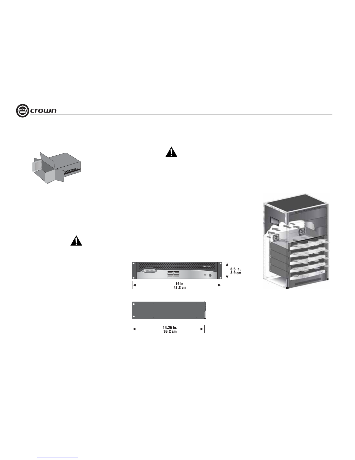
Use a standard 19-inch (48.3 cm) equipment
rack. See Figure 3.1 for amplifier dimensions.
You may also stack amps without using a cabinet.
NOTE: When transporting, amplifiers should be
supported at both front and back.
3.3 Ensure Proper Cooling
When using an equipment rack, mount units
directly on top of each other. Close any open
spaces in rack with blank panels. DO NOT
block front or rear air vents. The side walls of
the rack should be a minimum of two inches
(5.1 cm) away from the amplifier sides, and the
back of the rack should be a minimum of four
inches (10.2 cm) from the amplifier back panel.
Figure 3.2 illustrates standard amplifier airflow.
Figure 3.1 CTs 2-Channel Series Dimensions
Figure 3.2 Airflow
3 Setup
FRONT
Page 11
page 11
CTs Power Amplifiers
Operation Manual
3.4 Choose Input Wire
and Connectors
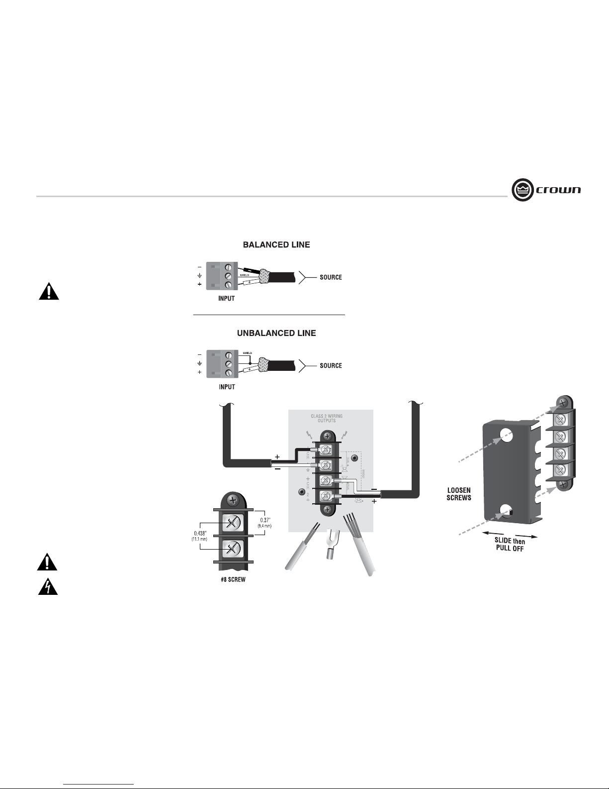
Figure 3.3 shows connector pin assignments for
balanced wiring, and Figure 3.4 shows connector pin assignments for unbalanced wiring.
NOTE: Custom wiring should only be performed by qualified personnel.
3.5 Choose Output Wire and Connectors
A protective cover is installed over the barrierstrip output. Some models have a cover with two
holes. To remove this type of cover:
1. Loosen screws inside top and bottom holes of
cover (see Figure 3.6).
2. Slide cover to left or right, then pull it off away
from the amplifier.
3. Tighten screws.
Crown recommends using professionally con-
structed, high-quality, two- or four-conductor,
heavy gauge speaker wire and connectors. You
may use terminal forks up to 10 AWG or bare
wire for your output connectors (see Figure 3.5).
To prevent the possibility of short-circuits, wrap
or otherwise insulate exposed loudspeaker cable
connectors. For best results, Crown recommends Panduit part #PV10-10LF-L or equivalent
terminal fork. Screw spacing is shown in Figure
3.5.
Using the guidelines below, select the appropri-
ate size of wire based on the distance from
amplifier to speaker (low-impedance loads only).
CAUTION: Never use shielded cable for
output wiring.
Replace output cover after output wiring
is complete.
Distance Wire Size
up to 25 ft. (7.6m) 16 AWG
26-40 ft. (7.9-12.2m) 14 AWG
41-60 ft. (12.5-18.3m) 12 AWG
> 60 ft (18.3m) 10 AWG
Figure 3.5 Typical Output Connector Wiring
3 Setup
Figure 3.3
Balanced Input
Connector Wiring
Figure 3.4
Unbalanced Input
Connector Wiring
Figure 3.6 How to Remove the Two-Holed
Barrier-Block Cover
Page 12
Operation Manual
CTs Power Amplifiers
page 12
3.6 Wire Your System
3.6.1 Dual 8/4/2 Mode
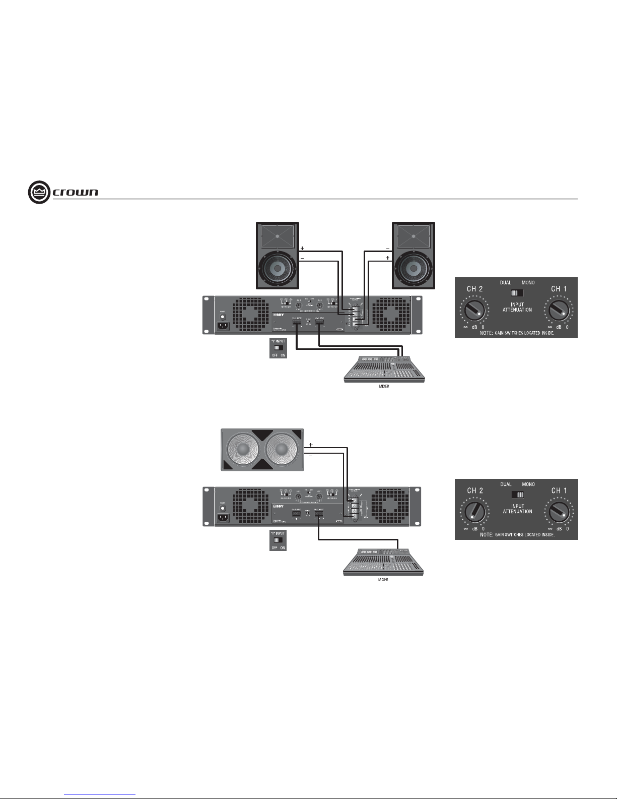
Typical input and output wiring, along with Attenuator
and Mode Switch settings are shown in Figures 3.6 and
3.7. Make sure the Mode switch is set to the “Dual” position when operating in Dual mode.
INPUTS: Connect input wiring for each channel. The Y
switch on the rear PIP panel can be used to parallel the
channel inputs when only mono input signals are necessary. The amplifier’s channel outputs are still independent.
OUTPUTS: Maintain proper polarity (+/–) on
output connectors.
Connect the Channel 1 speaker’s positive (+) lead to
amplifier Channel 1 positive terminal; repeat for negative
(–). Repeat Channel-2 wiring as for Channel 1. Refer to
Section 3.5 for output connector pin assignments.
3.6.2 Bridge-Mono 16/8/4 Mode
Typical input and output wiring, along with Attenuator
and Mode Switch settings, are shown in Figures 3.8 and
3.9. Make sure the Mode switch is set to the “Mono”
position when operating in Bridge-Mono mode.
INPUTS: Connect input wiring to Channel 1 only.
OUTPUTS: Connect the speaker across the positive ter-
minals of each channel pair. Do not use the negative terminals of the channel pair when the pair is being
operated in Bridge-Mono mode. Refer to Section 3.5 for
output connector pin assignments.
NOTE: Crown provides a reference of wiring pin assignments for commonly used connector types in the Crown
Amplifier Application Guide available at
www.crownaudio.com.
NOTE: When operating in Bridge-Mono mode,
turn down (full CCW) the Input Attenuator for
Channel 2. The Channel-1 Input Atttenuator
works both channels.
See the next page for constant-voltage operation.
Figure 3.7 System Wiring, Dual Mode.
Figure 3.8 Attenuator and Mode-
Switch Settings for Dual Mode
Figure 3.9 System Wiring, Bridge-Mono Mode
Figure 3.10 Attenuator and Mode-
Switch Settings for Bridge-Mono Mode
3 Setup
Always route the input and output wires in
separate bundles.
Page 13
page 13
CTs Power Amplifiers
Operation Manual
3.6.3 Dual 70V/100V Mode
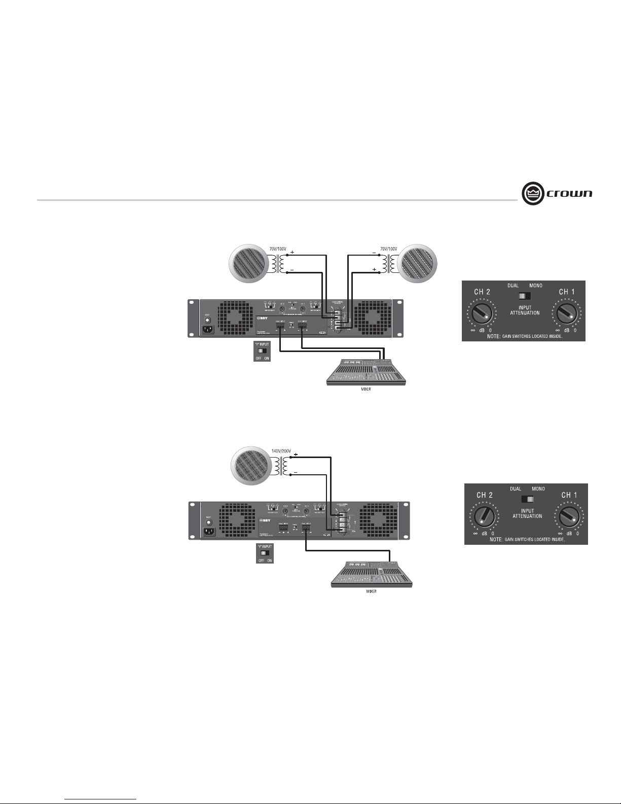
Typical input and output wiring, along with Attenuator and Mode Switch settings are shown in Figures 3.10 and 3.11. Make sure the Mode switch is
set to the “Dual” position when operating in Dual
mode.
INPUTS: Connect input wiring to both channels.
OUTPUTS: In Dual Mode, the CTs 600/1200 can
power 25/50/70V lines; the CTs 2000/3000 can
power 25/50/70/100V lines. Connect each channel of output connectors to speakers that have the
appropriate transformers.
.
3.6.4 Bridge-Mono 140V/200V Mode
Typical input and output wiring, along with Attenuator and Mode Switch settings are shown in Figures 3.12 and 3.13. Make sure the Mode switch is
set to the “Mono” position when operating in
Bridge-Mono mode.
INPUTS: Connect input wiring to Channel 1 only.
OUTPUTS: In Bridge-Mono mode, the CTs 600/
1200 can power 140V lines; the CTs 2000/3000
can power 140V and 200V lines. Connect speakers with 140V or 200V transformers across the
positive terminals of the channel pair. Do not use
the negative terminals of the channel pair when
the pair is being operated in Bridge-Mono mode.
Refer to Section 3.5 for output connector pin
assignments.
NOTE: When operating in Bridge-Mono
mode, turn down (full CCW) the Input
Attenuator for Channel 2. The Channel-1
Input Attenuator works both channels.
Figure 3.11 System Wiring and Y-Switch Setting for 70V/100V Operation
Figure 3.12 Attenuator and Mode-Switch
Settings for 70V/100V Operation
Figure 3.13 System Wiring and Y-Switch Setting for 140V/200V Operation
Figure 3.14 Attenuator and Mode-Switch
Settings for 140V/200V Operation
3 Setup
Always route the input and output wires in
separate bundles.
Page 14
Operation Manual
CTs Power Amplifiers
page 14
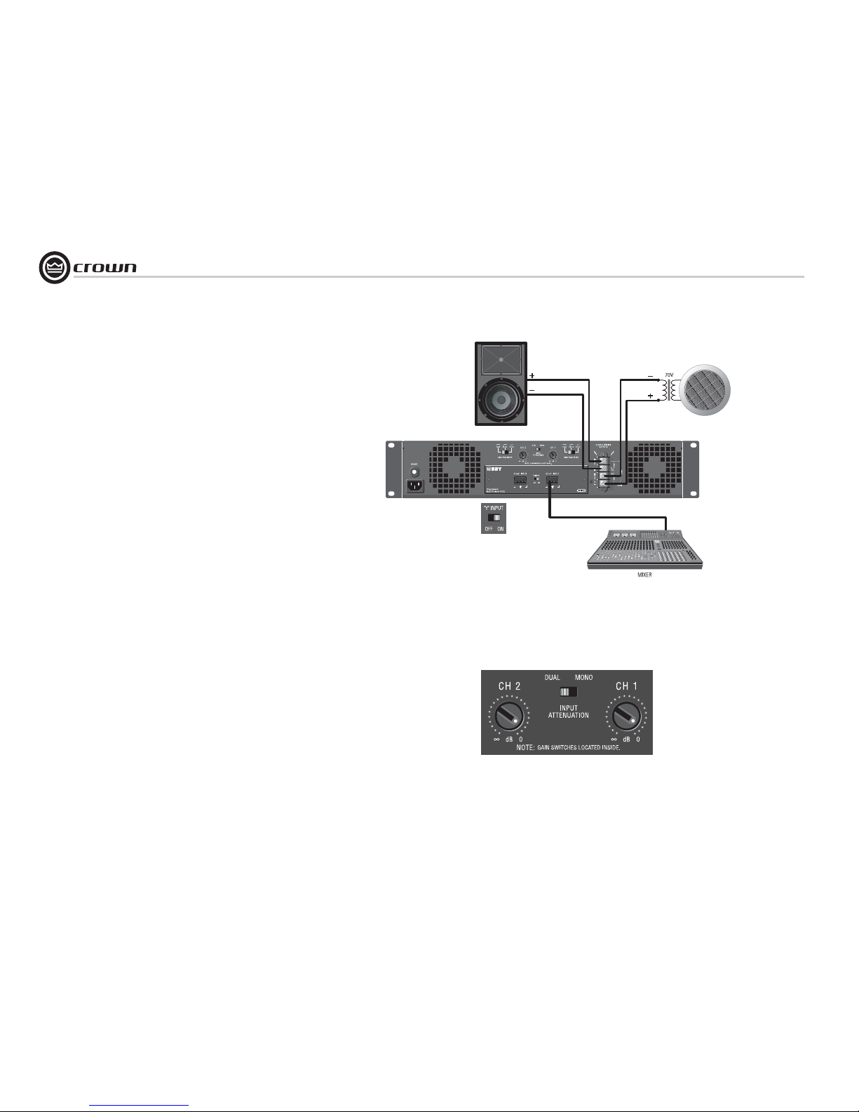
3.6.5 Dual Mode with “Y” Input
See Figure 3.14. This configuration feeds a mono
signal to both Channel 1 and Channel 2. In the
example in Figure 3.14, Channel 1 is driving a lowimpedance loudspeaker and Channel 2 is driving a
loudspeaker with a 70V transformer.
INPUTS:
Connect the signal to the Channel 1 input. On the
back panel, set the “Y” Input Switch to ON.
OUTPUTS:
Connect the Channel 1 speaker’s positive (+) lead
to Channel 1 positive terminal of amp; repeat for
negative (–).
Connect the Channel 2 speaker’s positive (+) lead
to Channel 2 positive terminal of amp; repeat for
negative (–).
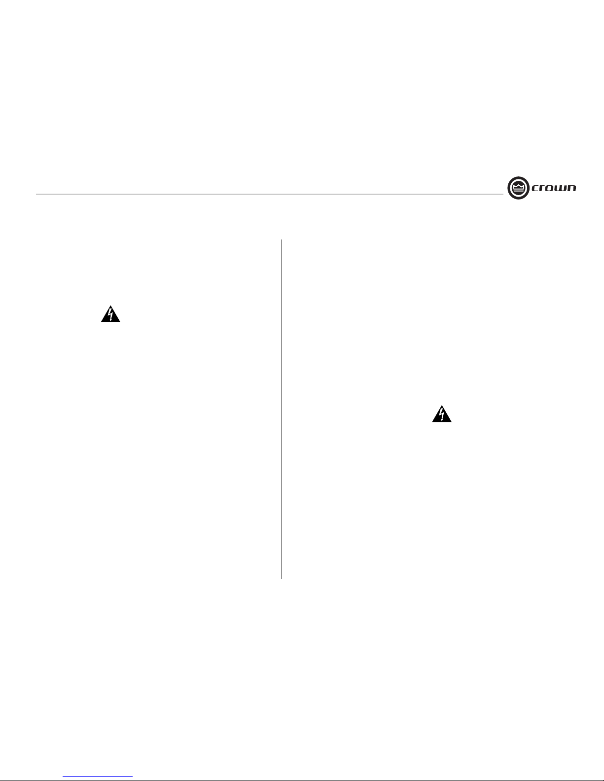
See Figure 3.15. Turn up both Input Attenuators and
set the Mode Switch to Dual.
NOTE: When the “Y” Input Switch is on, the Channel 2 input can be used to daisy-chain to another
amplifier.
Figure 3.15 System Wiring for “Y” Input Mode
Figure 3.16
Attenuator and Mode-Switch
Settings for “Y” Input Mode
3 Setup
Always route the input and output wires in
separate bundles.
Page 15
page 15
CTs Power Amplifiers
Operation Manual
3.7 Connect to AC Mains
On the back panel, check whether your amplifier is labeled
for 120V or 220-240V AC mains. Connect your amplifier
to the corresponding AC mains power source (power outlet) with the supplied AC power cordset. First, connect the
IEC end of the cordset to the IEC connector on the amplifier. Then, with the amplifier in the OFF position, plug the
other end of the cordset into the AC mains.
WARNING: The third prong of this connector
(ground) is an important safety feature. Do not
attempt to disable this ground connection by
using an adapter or other methods.
Amplifiers don’t create energy. The AC mains voltage and
current must be sufficient to deliver the power you expect.
Check the amplifier’s back-panel label which specifies the
required AC mains voltage and frequency. The AC mains
voltage must be no more than 15% above the required
voltage, and no less than 25% below the required voltage.
The AC mains frequency must be within the required frequency range. If you are unsure of the output voltage of
your AC mains, please consult your electrician.
3.8 Startup Procedure
Use the following procedure when first turning on your
amplifier:
1. Turn down the level of your audio source.
2. Turn down the level controls of the amplifier.
3. Turn on the “Power” switch. The Power indicator
should glow. Wait for the “Ready” LED to illuminate.
4. Turn up the level of your audio source to an optimum
level.
5. Turn up the Level controls on the amplifier until the
desired loudness or power level is achieved. Verify
that the Signal LED is flashing.
6. Turn down the level of your audio source to its normal
range.
If you ever need to make any wiring or installation
changes, don’t forget to turn off the amplifier and disconnect the power cord.
For help with determining your system’s optimum gain
structure (signal levels) please refer to the Crown Ampli-
fier Application Guide, available online at
www.crownaudio.com.
4 Operation
4.1 Precautions
Your amplifier is protected from internal and external
faults, but you should still take the following precautions
for optimum performance and safety:
1. Before use, your amplifier first must be configured for
proper operation, including input and output wiring
hookup. Improper wiring can result in serious operating difficulties. For information on wiring and configuration, please consult the Setup section of this
manual or, for advanced setup techniques, consult
Crown’s Amplifier Application Guide available online
at www.crownaudio.com.
2. Use care when making connections, selecting signal
sources and controlling the output level. The load you
save may be your own!
3. Do not short the ground lead of an output cable to the
input signal ground. This may form a ground loop
and cause oscillations.
4. Never connect the output to a power supply,
battery or power main. Electrical shock may
result.
5. Tampering with the circuitr y, or making unauthorized
circuit changes may be hazardous and invalidates all
agency listings.
6. Do not operate the amplifier with the red Clip LEDs
constantly flashing.
7. Do not overdrive the mixer, which will cause clipped
signal to be sent to the amplifier. Such signals will be
reproduced with extreme accuracy, and loudspeaker
damage may result.
8. Do not operate the amplifier with less than the rated
load impedance. Due to the amplifier’s output protection, such a configuration may result in premature
clipping and speaker damage.
Remember: Crown is not liable for damage that results
from overdriving other system components.
3 Setup
Page 16
Operation Manual
CTs Power Amplifiers
page 16
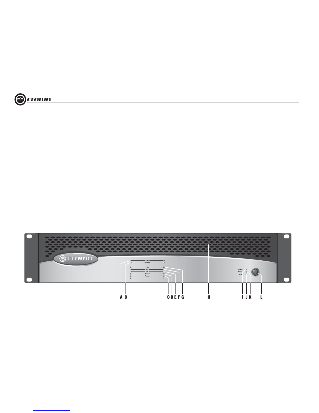
4.2 Front Panel Controls
and Indicators
A. Fault Indicator
Red LED, one per channel, flashes when
the amplifier output channel has stopped
operating. Usually this means that the
amplifier must be serviced.
B. Thermal Indicator
Red LED, one per channel, illuminates
when the channel has shut down, or is
very near shutting down, due to thermal
stress or overload.
C. Ready Indicator
Green LED, one per channel, illuminates
when the channel is initialized and ready to
produce audio output. Indicator is off when
the channel is set to standby mode via the
System Architect or IQ Control Software
packages.
Signal Indicators
Three green LEDS per channel indicate the
amplifier’s input and output signal levels.
From bottom to top the LEDs are:
D. Signal: input signal is above –40 dBu.
E. –20 dB: amplifier output is within 20 dB of
clipping.
F. –10 dB: amplifier output is within 10 dB of
clipping.
G. Clip Indicator
Red LED, one per channel, illuminates
when the channel’s output signal reaches
the onset of audible clipping. The Clip
Indicator also will illuminate during Thermal Level Control (TLC) limiting or when
the input compressor/limiter is protecting
the amplifier from input overload.
H. Cooling Vents
Front-to-rear forced airflow.
I. Power Indicator
Blue LED indicates AC power has been
applied and is within the safe operating
range of the power supply. The LED will
flash when the AC line voltage is approximately 15% above or 25% below the nominal rated value.
J. Data Indicator
Yellow LED indicates control activity This
LED is driven by the IQ-PIP2 module via
the PIP2
interface. Note: Data indicator
flashes only when the installed PIP module
is polled for data, or is polled to see
whether it is online.
K. Bridge Mode Indicator
Yellow LED illuminates when the rearpanel Mode Switch is set to the “Bridge”
position
L. Power Switch
Push-on / push-off switch.
Figure 4.1 CTs 600 front panel.
4 Operation
Page 17
page 17
CTs Power Amplifiers
Operation Manual
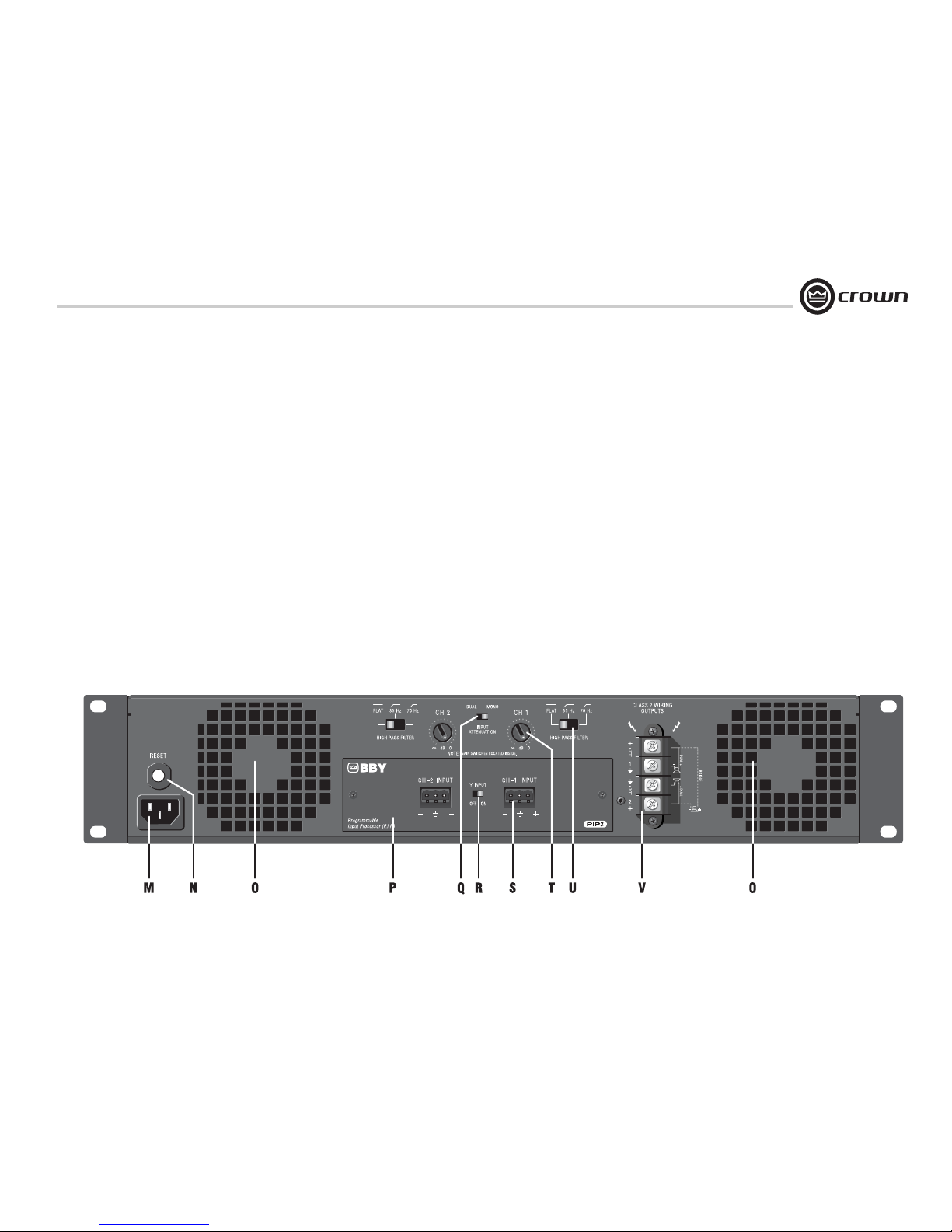
4.3 Back Panel Controls
and Connectors.
CTs 2000/3000 back panel is shown.
CTs 600/1200 look slightly different near
the Reset button.
M. Power Cord Connector
Standard 15 amp IEC inlet. A circuit
breaker located near the IEC power inlet
protects the amplifier from excessive AC
current draw.
N. Reset Switch
Resets the circuit breaker that protects the
power supply.
O. Ventilation Grille
Air flow is front to back. Do not block the
ventilation grilles.
P. PIP ™ Input Panel
PIP2-BBY module includes two balanced
3-pin removable barrier connectors. The
“Y” Input Switch is described u nder
letter R.
Sensitivity Switches
Behind the input panel are the Input Sensitivity Switches. One 3-position switch per
channel selects various sensitivity settings. See Section 5.2.4 for details and
diagram.
Q. Mode Switch
This two-position switch is used to select
the amplifier’s mode of operation: Dual or
Bridge Mono.
Dual mode is used for 2/4/8 ohms, for 70V
operation with the CTs 600/1200, and for
70/100V operation with the CTs 2000/
3000.
Bridge mode is used for 4/8/16 ohms, for
140V operation with the CTs 600/1200,
and for 100/140/200V operation with the
CTs 2000/3000.
R. “Y” Input Switch
When set to ON, this switch parallels the
input signals of the two channels, for use
when the input signal is mono. The amplifier’s channel outputs are still independent.
The “Y” Input Switch also can be used to
daisy-chain the signal to another amplifier.
See Section 3.6.5 for details.
S. Input Connectors
Balanced 3-pin terminal block connectors,
one per channel.
T. Channel Level Controls
One 21-position detented rotary attenuator
per channel, ranging from –100 dB to 0 dB
gain.
U. High-Pass Filter
One 3-position switch per channel selects
between OFF, 35Hz and 70Hz 3rd-order filters.
V. Speaker Connectors
One four-pole touch-proof terminal strip.
Accepts up to 10 AWG terminal forks.
Output Cover (not shown)
This covers the output connectors, protecting users from the connectors’ potentially high voltage. This cover is required
for Class 2 wiring installations. See Section 3.5 for details on removing covers that
have two holes.
4 Operation
Figure 4.2 CTs 2000 and 3000 Back Panel Controls and Connectors
Page 18

Operation Manual
CTs Power Amplifiers
page 18
NOTE: For detailed information about
these Crown amplifier features, please
consult the Crown Amplifier Application
Guide, available on the Crown website
at www.crownaudio.com
5.1 Protection Systems
Your Crown amplifier provides extensive protection and diagnostic capabilities, including
thermal level control, fault indicators, highpass filtering, DC protect, AC under/over voltage protection, inrush limiting, and variablespeed fans.
5.1.1 Thermal Level Control (TLC)
If the amplifier becomes too hot for safe operation, the light will shine brightly a nd TLC will
engage the input compressor. By compressing
the input, the amplifier will not generate as
much heat and will have a chance to cool down.
The degree of compression is proportional to
the amount of overheating. This feature allows
the show to go on, rather than having the
amplifier shut down.
5.1.2 Junction Temperature Simulation (JTS) (CTs 600/1200 only)
JTS circuitry simulates the operation of the
amplifier’s output transistors, and compares it
against the transistors known Safe Operation
Area (SOA). If JTS sees that more power is
about to be asked of the output devices than
they are capable of delivering under the present
conditions, JTS immediately limits the drive
level until it falls within the SOA. Limiting is
proportional and kept to an absolute minimumonly what is required to prevent the possibility
of output transistor damage.
This level of protection enables Crown to
increase output transistor utilization while also
greatly increasing amplifier reliability.
5.1.3 Fault
The amplifier will light the Fault LED if the
amplifier output stage stops operating. If this
happens, see Section 8 for servicing information.
5.1.4 High-Pass Filters
Very low frequency signals contain no useful
musical energy, waste valuable amplifier power
and headroom, and can be damaging to your
speakers. Your Crown amplifier provides highpass filters to remove these signals from each
channel’s output.
On the back panel are two 3-position 3rd-order
high-pass filter switches (one per channel) with
selections of Off, 35Hz and 70 Hz.
5.1.5 Low-Pass Filters
Gaussian-approximation ultrasonic filters prevent ultrasonic feedback and HF burnout in
drivers. This type of filter preserves transient
response better than a Butterworth filter.
5.1.6 AC Under/Over Voltage
Protection
If the AC line voltage drops below 25% or rises
above 15% of the nominal operating voltage of
the amplifier, the amplifier’s power supply turns
off and the blue Power LED flashes. The amplifier will turn back on when the AC line voltage
returns to safe operating levels (within +15% /
-25%).
5.1.7 Circuit Breaker
A circuit breaker located near the IEC power
inlet protects the amplifier from excessive AC
current draw.
5.1.8 DC Output Servo
The output servo circuit protects your drivers
by eliminating DC offset, even in the presence
of very large asymmetrical signals.
5.1.9 Inrush Limiting
A soft-start circuit in the power supply minimizes the amplifier’s current draw during
power-on.
5.1.10 Variable-speed Fans
Two continuously variable speed fans direct the
airflow through the amplifier for cooling.
5.2 Advanced Features
5.2.1 Switching Power Supply
Crown’s Switching Power Supply minimizes the
amplifier’s weight.
Typical non-switching power supplies require
large, heavy transformers in order to produce
the required power at the output stage. These
transformers must be large to operate at 50 to
60 Hz (standard AC supplied by the power
company).
By contrast, switching power supplies can
operate with a much smaller (and lighter) transformer because they first convert the AC up to a
much higher frequency, thereby reducing
waste.
The power supply is voltage-specific, allowing
use in regions using 120V or 240V.
5.2.2 Input Compressor
Prevent input/output overload.
5.2.3 Sleep Circuit
Lowers standby power consumption by shutting down the high-voltage supplies during idle
periods.
NOTE: By default, the sleep circuit is not active
on the CTs 600/1200, but may be activated as a
service option.
5 Advanced Features
and Options
Page 19
page 19
CTs Power Amplifiers
Operation Manual
5 Advanced Features
and Options
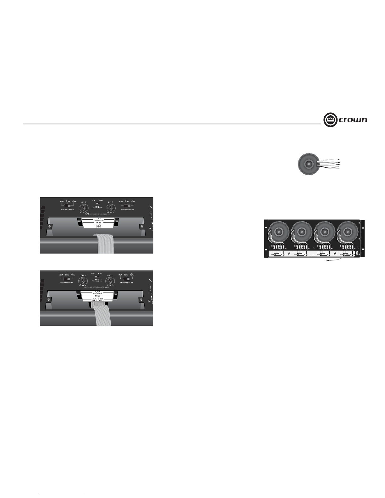
5.2.4 Input Sensitivity Switches
See Figures 5.1 and 5.2. To access the Input Sensitivity Switches, turn off the
amplifier and remove the PIP2-BBY Input Panel. The switches are in the top surface
of the cavity behind the Input Panel. One 3-position switch per channel selects
among these settings: CTs 600/1200: 1.4V (8/4 ohms), 26 dB gain, and 1.4V (70V
operation). CTs 2000/3000: 1.4V (8/4 ohms), 26 dB gain, and 1.4V (70V) / 2V
(100V). The Specifications chapter lists the input sensitivity for the 26 dB gain setting.
5.3 Options
T-170V: See Figure 5.3. This is an autoformer that
allows 100V output from the CTs 600/1200, and
allows other amplifiers without direct constant voltage
output to be easily integrated into distributed systems.
TP-170V: See Figure 5.4. This is a rack-mountable
panel with four autoformers as described above.
PIP Modules
Versatile PIP (Programmable Input Processor) modules provide flexible expansion features that can be
added to customize the amplifier. PIP modules plug
into the connector inside the back panel of the amplifier. PIP modules are available with features ranging
from error-driven compressor/limiters to crossovers to
remote control and monitoring via IQwic™ or System
Architect software. Your amplifier is a PIP2 amplifier,
which means it can take advantage of the many
advanced features found in PIP2 modules. The CTs
Series 2-channel models do not accept earlier PIP
modules.
Visit the Crown website at www.crownaudio.com, or
contact Crown Customer Service, for descriptions of
available PIP and PIP2 modules.
Figure 5.2 Input Sensitivity Switches for CTs 2000/3000
Figure 5.1 Input Sensitivity Switches for CTs 600/1200
Figure 5.3 T-170V
Figure 5.4 TP-170V (back view)
Page 20
Operation Manual
CTs Power Amplifiers
page 20
5 Advanced Features
and Options
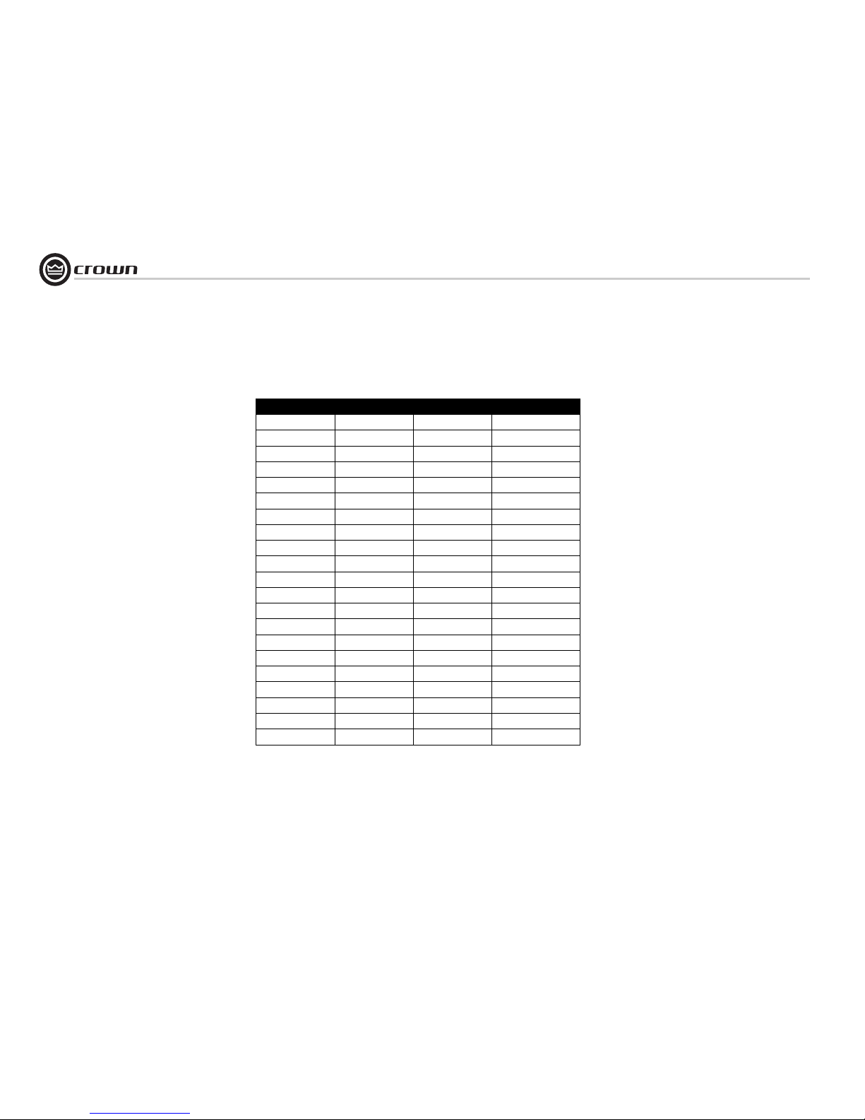
5.3.1 Nominal Attenuation Settings
The signal level for each input can be attenuated repeatably by
adjusting the 21-step Level Control (see Section 4.3). Figure 5.5
shows the attenuation in dB for each detent. The setting of the
input-sensitivity switch varies the actual attenation as shown.
The accuracy of the attenuation varies with the setting: see
Tolerance (dB).
Detent 26 dB Tolerance (dB) 4/8 ohm or 70/100V
0 (full CCW) OFF — OFF
1 48.0 ±6 54.0
2 36.0 ±6 42.0
3 24.0 ±3 30.0
4 21.0 ±3 26.0
5 18.0 ±3 24.0
6 15.0 ±3 22.0
7 13.5 ±3 20.0
8 12.0 ±1.5 18.0
9 10.5 ±1.5 16.0
10 9.0 ±1.5 14.5
11 8.0 ±1.5 13.0
12 7.0 ±1.5 11.0
13 6.0 ±1 9.5
14 5.0 ±1 8.0
15 4.0 ±1 6.5
16 3.0 ±1 5.0
17 2.0 ±1 3.5
18 1.0 ±1 1.5
19 0.5 +1 –5 0.5
20 (full CW) 0.0 — 0.0
Figure 5.1 Level-control Attenuation per Detent for CTs 2-Channel Amplifiers
Attenuation in dB
Page 21
page 21
CTs Power Amplifiers
Operation Manual
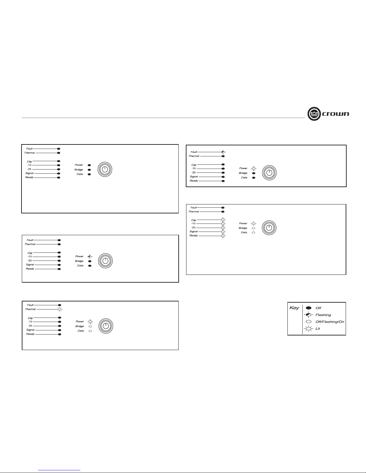
CONDITION: Power indicator is
off.
POSSIBLE REASON
• The amplifier has lost AC power.
• The amplifier’s Power switch is off.
• The amplifier is not plugged into the
power receptacle.
• The amplifier output level is so high that
the power supply circuit breaker has
tripped. Allow the unit to cool. Turn down
the Level controls. Press the Reset Switch
on the back panel.
CONDITION: Power indicator is
flashing.
POSSIBLE REASON:
• The AC line voltage has dropped below
20% or has risen above 10% of the nominal line voltage of the power supply.
CONDITION: Thermal indicator is
on.
POSSIBLE REASON:
• The amplifier is becoming too hot for safe
operation. Allow amplifier to cool. Check
for loads less than 2 ohms, and for
excessive input levels. Check for proper
ventilation and proper mode-switch setting.
CONDITION: Fault indicator is
flashing.
POSSIBLE REASON:
• The amplifier channel has stopped operating. Refer the unit to an authorized Crown
Service Center.
CONDITION: Distorted sound.
POSSIBLE REASON:
• Load is wired incorrectly or Stereo/Mono
mode switch is set incorrectly. Check both.
• Input is overlaoded by a signal level that is
too high. Turn down your amplifier level
controls, or turn down the input signal, until
the clip light goes out.
Note: If the signal sounds distorted even though
the Clip LED is off, the input signal may be distorted before it reaches the amplifier input. Check
gain staging and output levels of the mixer or
preamp.
6 Troubleshooting
“Off/Flashing/On” above means that
the LED can be off, or flashing, or on.
Page 22
Operation Manual
CTs Power Amplifiers
page 22
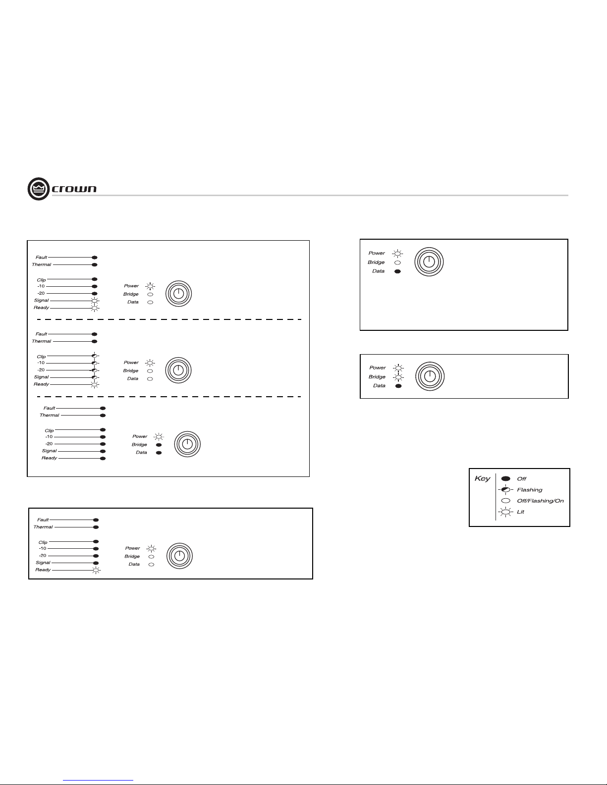
CONDITION: No sound, even though
the amp has power. Power LED is on with-
out flashing and the amp is receiving an input signal. Signal indicator is flashing.
POSSIBLE REASON:
• Speakers not connected.
• Open circuit due to speaker failure.
• There is a short on the amplifier output. First
disconnect your speakers from the affected
channel(s) one by one to determine if one of
the loads is shorted.
CONDITION: No input signal. Signal
indicator is not flashing even though audio is
applied, and the channel is ready..
POSSIBLE REASON:
• Input signal level is very low.
• Level controls are turned down.
CONDITION: Data indicator not flashing, even though PIP module is
installed and host computer control
software is active.
POSSIBLE REASON:
• Cable between computer and PIP module is
broken or not connected.
Note: Data indicator flashes only when the installed
PIP2 module is polled for data, or is polled to see
whether it is online.
6 Troubleshooting
“Off/Flashing/On” above means that
the LED can be off, or flashing, or on.
• Ready LED is off. Channel has been set to
standby mode via the control system.
CONDITION: Bridge LED is lit.
POSSIBLE REASON:
• Amplifier is in bridge-mono mode.
Page 23
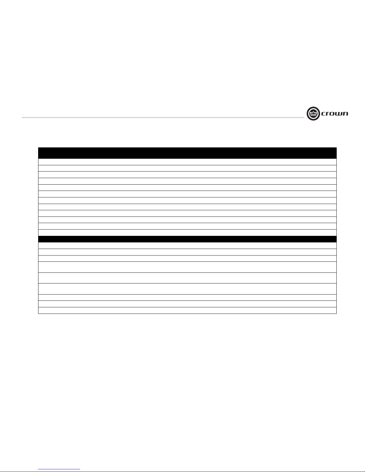
page 23
CTs Power Amplifiers
Operation Manual
Minimum Guaranteed Power
(20 Hz - 20 kHz)
CTs 600
Power at 0.1% THD
CTs 1200
Power at 0.1% THD
CTs 2000
Power at 0.35% THD
CTs 3000
Power at 0.35% THD
2-ohm Dual (per ch.) 150W 250W 1000W 1500W
4-ohm Dual (per ch.) 300W 600W 1000W 1500W
8-ohm Dual (per ch.) 300W 600W 1000W 1250W
16-ohm Dual (per ch.) 300W 300W 625W 625W
70V Dual (per ch.) 300W 600W 1000W 1500W
100V Dual (per ch.) 300W* 600W* 1000W 1500W
4-ohm Bridge 300W 500W 2000W 3000W
8-ohm Bridge 600W 1200W 2000W 3000W
16-ohm Bridge 600W 1 200W 2000W 2500W
100V Bridge 600W* 1200W* 2000W 3000W
140V Bridge 600W 1 200W 2000W 3000W
200V Bridge 600W* 1200W* 2000W 3000W
Performance CTs 600 CTs 1200 CTs 2000 CTs 3000
Frequency Response (at 1 watt, 20 Hz - 20 kHz) ± 0.25 dB ± 0.25 dB ± 0.25 dB ± 0.25 dB
Signal to Noise Ratio (ref. rated power, 20 Hz to 20 kHz, A-weighted) < 105 dB < 105 dB < 105 dB < 105 dB
Total Harmonic Distortion (THD) at full rated power, from 20 Hz to 20 kHz < 0.1% < 0.1% < 0.35% < 0.35%
Intermodulation Distortion (IMD) 60 Hz and 7 kHz at 4:1, from –40 dB to
full rated power
< 0.1% < 0.1% < 0.35% < 0.35%
Damping Factor:
10 Hz to 100 Hz > 3000 > 3000 > 3000 > 3000
Crosstalk (below rated power)
20 Hz to 1kHz > 80 dB > 80 dB > 80 dB > 80 dB
Common Mode Rejection (CMR) (20 Hz to 1 kHz, typical) 50 dB 50 dB 50 dB 50 dB
DC Output Offset < 2 mV < 2mV < 2 mV < 2 mV
Input Impedance nominally balanced, nominally unbalanced 10 k ohms, 5 k ohms 10 k ohms, 5 k ohms 10 k ohms, 5 k ohms 10 k ohms, 5 k ohms
7 Specifications
* With T-170V or TP-170V.
Page 24
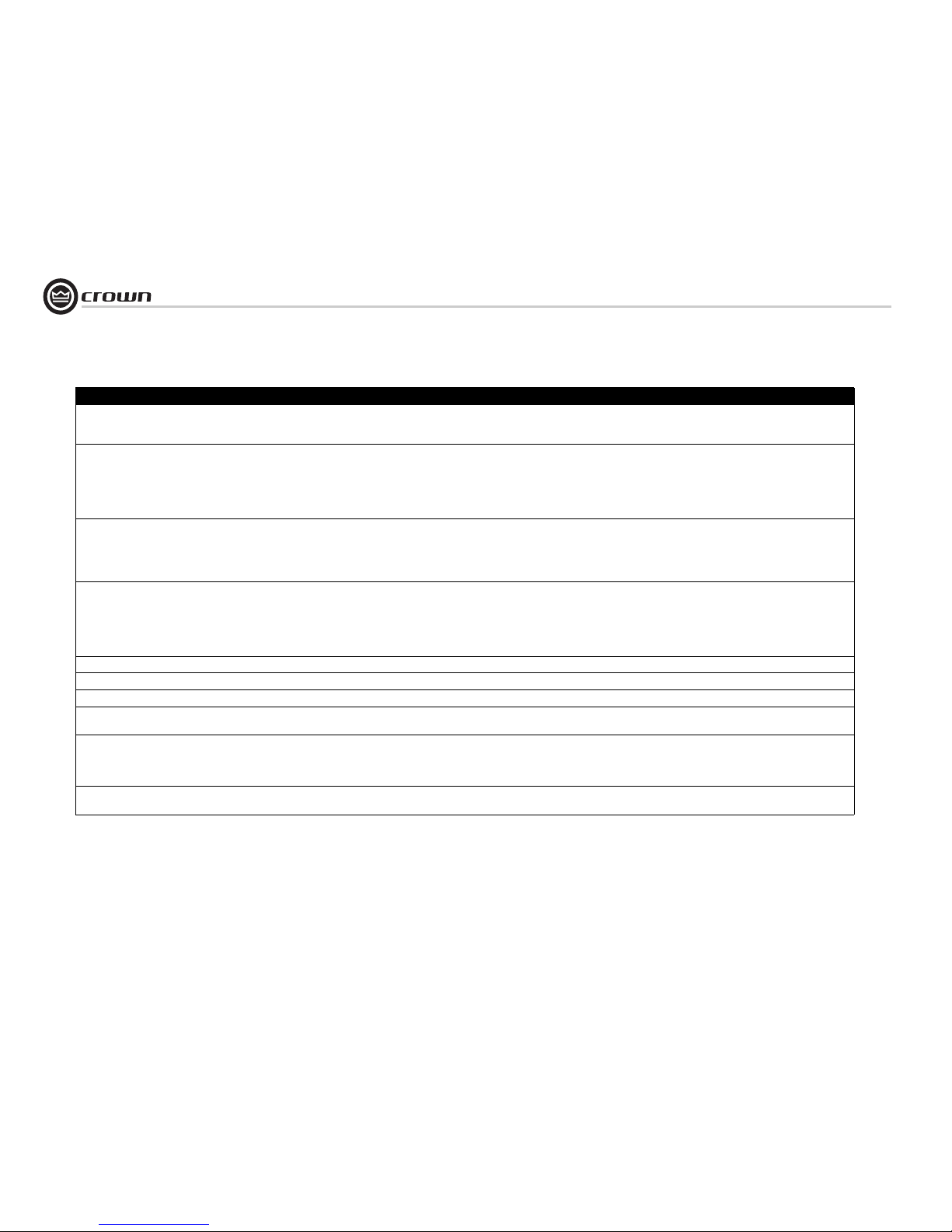
Operation Manual
CTs Power Amplifiers
page 24
Perfor mance CTs 600 CTs 1200 CTs 2000 CTs 3000
Maximum Input Level
Before input compression
Absolute maximum
+20 dBu
+ 32 dBu
+20 dBu
+ 32 dBu
+20 dBu
+ 32 dBu
+20 dBu
+ 32 dBu
Load Impedance (Note: Safe with all types of loads)
Stereo
Bridge Mono
2, 4, 8, 16 ohms, 70V, and 100V*
4, 8, 16, 100V*, 140V and 200V*
2, 4, 8, 16 ohms, 70V, and 100V*
4, 8, 16, 100V*, 140V and 200V*
2, 4, 8, 16, 70V,
and 100V
4, 8, 16, 140V , 200V
2, 4, 8, 16, 70V,
and 100V
4, 8, 16, 140V, 200V
Voltage Gain (at maximum level setting)
8/4 Ohm Operation
26 dB
70V Operation
100V Operation
35:1 (31 dB)
20:1 (26 dB)
50:1 (34 dB)
50:1 (34 dB)
20:1 (26 dB)
50:1 (34 dB)
63.9:1 (36 dB)
20:1 (26 dB)
50:1 (34 dB)
50:1 (34 dB)
71.4:1 (37 dB)
20:1 (26 dB)
50:1 (34 dB)
50:1 (34 dB)
Input Sensitivity
2/4/8 ohms
70V
100 V
26 dB gain
1.4V
1.4V
4 ohm load: 1.74V.
8 ohm load: 2.46V
1.4V
1.4V
4 ohm load: 2.46V.
8 ohm load: 3.47V
1.4V
1.4V
2.0V
4 ohm load: 3.17V.
8 ohm load: 4.48V
1.4V
1.4V
2.0V
4 ohm load: 3.88V.
8 ohm load: 5.01V
Required AC Mains (+15%, – 25%) 120V/60 Hz, 230V/50 Hz 120V/60 Hz, 230V/50 Hz 120V/60 Hz, 230V/50 Hz 120V/60 Hz, 230V/50 Hz
Power Draw at Idle (120 VAC mains) 24W (Standby Mode) 24W (Standby Mode) 35W (Standby Mode) 35W (Standby Mode)
Overall Group Delay < 120 usec < 120 usec < 120 usec < 120 usec
Cooling Continuously variable speed
forced air, front-to-back airflow
Continuously variable speed
forced air, front-to-back airflow
Continuously variable speed
forced air, front-to-back airflow
Continuously variable speed
forced air, front-to-back airflow
Dimensions
Width
Height
Depth
19 in. (48.3 cm.)
3.5 in. (8.9 cm.)
14.25 in. (36.2 cm.)
19 in. (48.3 cm.)
3.5 in. (8.9 cm.)
14.25 in. (36.2 cm.)
19 in. (48.3 cm.)
3.5 in. (8.9 cm.)
14.25 in. (36.2 cm.)
19 in. (48.3 cm.)
3.5 in. (8.9 cm.)
14.25 in. (36.2 cm.)
Net Weight
Shipping Weight
22.8 lb (10.3 kg),
27.7 lb (12.6 kg)
23.4 lb (10.6 kg),
2 8 . 3 l b ( 1 2 . 8 k g )
27.0 lb (12.2 kg)
32.0 lb (14.5 kg)
27.7 lb (12.6 kg)
32.7 lb (14.8 kg)
7 Specifications
* With T-170V or TP-170V.
Page 25
page 25
CTs Power Amplifiers
Operation Manual
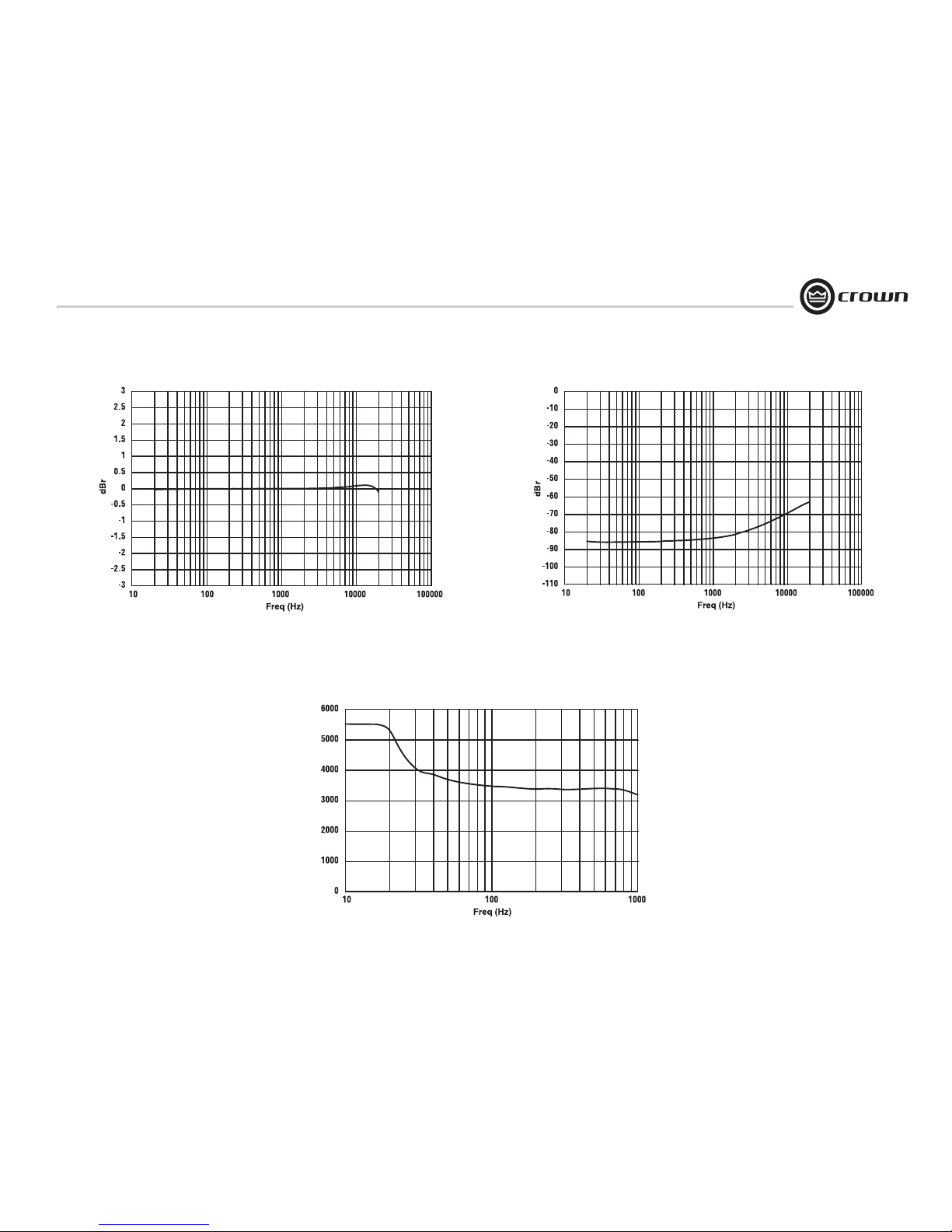
7 Specifications
Figure 7.1 CTs 600/1200 Typical Frequency Response (1 W, 8 ohms)
Figure 7.2 CTs 600/1200 Typical Crosstalk vs. Frequency
Figure 7.3
CTs 600/1200
Typical Damping Factor
vs. Frequency
Page 26
Operation Manual
CTs Power Amplifiers
page 26
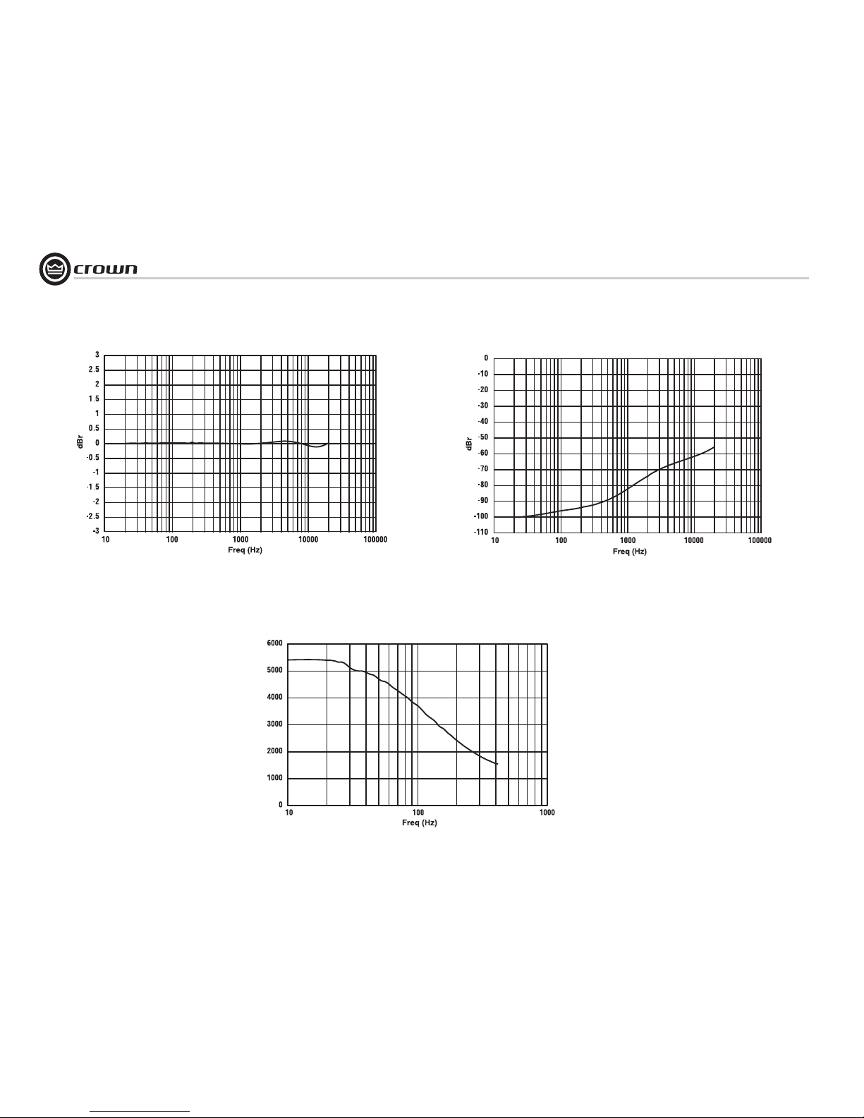
Figure 7.4 CTs 2000/3000 Typical Frequency Response (1W)
Figure 7.6
CTs 2000/3000
Typical Damping Factor
vs. Frequency
7 Specifications
Figure 7.5 CTs 2000/3000 Typical Crosstalk vs. Frequency
Page 27
page 27
CTs Power Amplifiers
Operation Manual
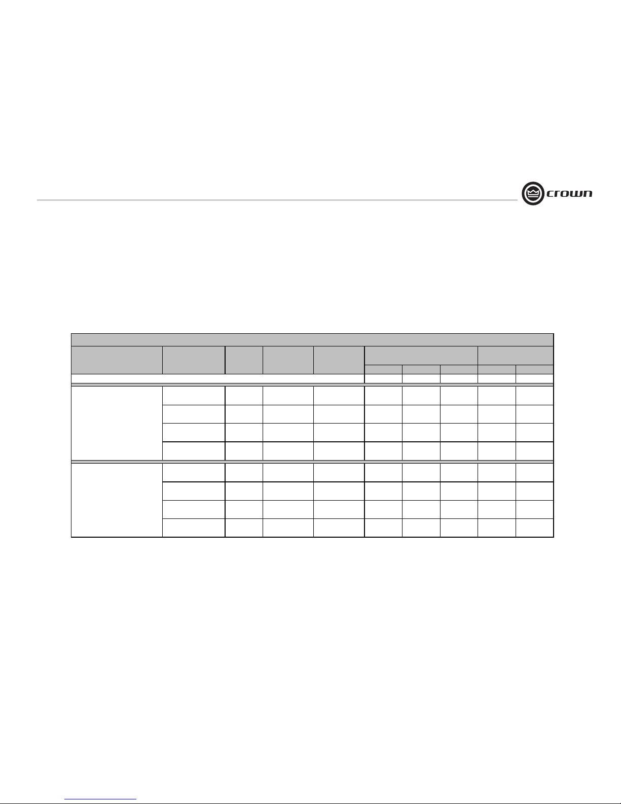
AC Power Draw and Thermal Dissipation:
Pink noise 12dB crest factor, bandwidth limited 22Hz to 22kHz.
Typical line impedance used.
Measurements made with 120VAC mains. Line current figures for 230VAC units derived by multiplying 120VAC figures by 0.5.
Data based on all channels driven.
watts in
watts out dissapated
Btu/hr kcal/hr
At Idle
60 0 60 205 52
1/8th Power Pink Noise 8 Ohms/Ch.
300x2
Typical of program material 16 Ohms Bridge
600
just at clip. 4 Ohms/Ch.
300x2
8 Ohms Bridge
600
2 Ohms/Ch.
150x2
4 Ohms Bridge
300
70V/Ch. 300x2
140/200V Bridge 600
1/3rd Power Pink Noise 8 Ohms/Ch.
300x2
Typical of program material 16 Ohms Bridge
600
with severe clipping. 4 Ohms/Ch.
300x2
8 Ohms Bridge
600
2 Ohms/Ch.
150x2
4 Ohms Bridge
300
70V/Ch. 300x2
140/200V Bridge 600
444
657
742
275
1760
2608
2942
1091
516
764
862
320
200
204
102
207
716
968
964
527
4.3
5.6
5.4
3.3
8.6
11.3
10.8
6.5
330
477
469
225
1307
1890
1859
892
383
554
545
261
78
78
38
75
461
631
583
336
2.9
3.7
3.5
2.1
5.8
7.4
7.0
4.2
CTs 600
Watts
Thermal Dissipation
Line Current
230VAC
Line Current
120VAC
Rated
Power
Load
8 AC Power Draw and Thermal Dissipation
Page 28
Operation Manual
CTs Power Amplifiers
page 28
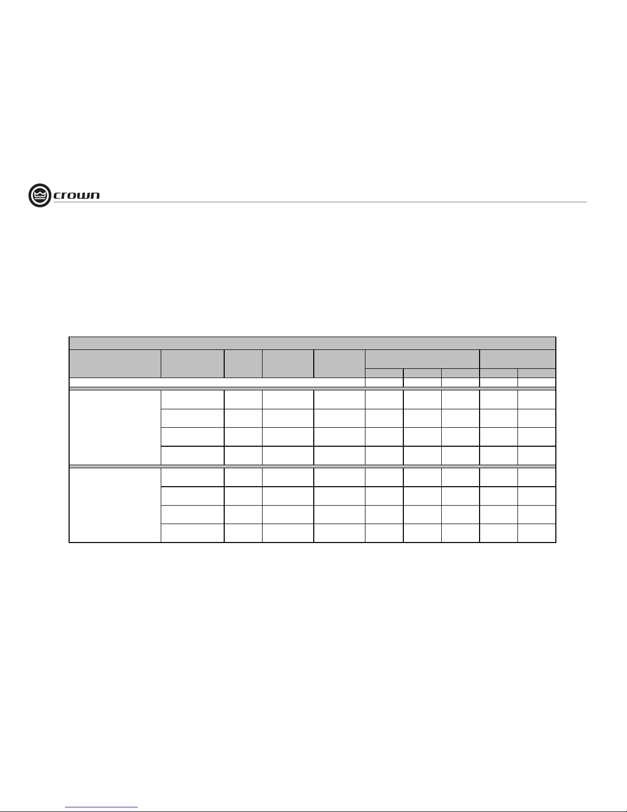
AC Power Draw and Thermal Dissipation:
Pink noise 12dB crest factor, bandwidth limited 22Hz to 22kHz.
Typical line impedance used.
Measurements made with 120VAC mains. Line current figures for 230VAC units derived by multiplying 120VAC figures by 0.5.
Data based on all channels driven.
watts in
watts out dissapated
Btu/hr kcal/hr
At Idle
60 0 60 205 52
1/8th Power Pink Noise 8 Ohms/Ch.
600x2
Typical of program material 16 Ohms Bridge
1200
just at clip. 4 Ohms/Ch.
600x2
8 Ohms Bridge
1200
2 Ohms/Ch.
250x2
4 Ohms Bridge
500
100V/Ch. 600x2
140/200V Bridge 1200
1/3rd Power Pink Noise 8 Ohms/Ch.
600x2
Typical of program material 16 Ohms Bridge
1200
with severe clipping. 4 Ohms/Ch.
600x2
8 Ohms Bridge
1200
2 Ohms/Ch.
250x2
4 Ohms Bridge
500
70V/Ch. 600x2
140/200V Bridge 1200
CTs 1200
Load
Rated
Power
Line Current
120VAC
Line Current
230VAC
Watts
Thermal Dissipation
7.6 3.8 641 157 484 1651 416
10.0 5.0 872 151 720 2458 620
8.8 4.4 1330 405 925 3158 796
7.6 3.8 641 157 484 1651 416
11.5 5.7 996 403 593 2025 511
15.5 7.8 1372 405 967 3300 832
903
996 403 593 2025 511
1217 168 1050 358213.4 6.7
11.5 5.7
8 AC Power Draw and Thermal Dissipation
Page 29
page 29
CTs Power Amplifiers
Operation Manual
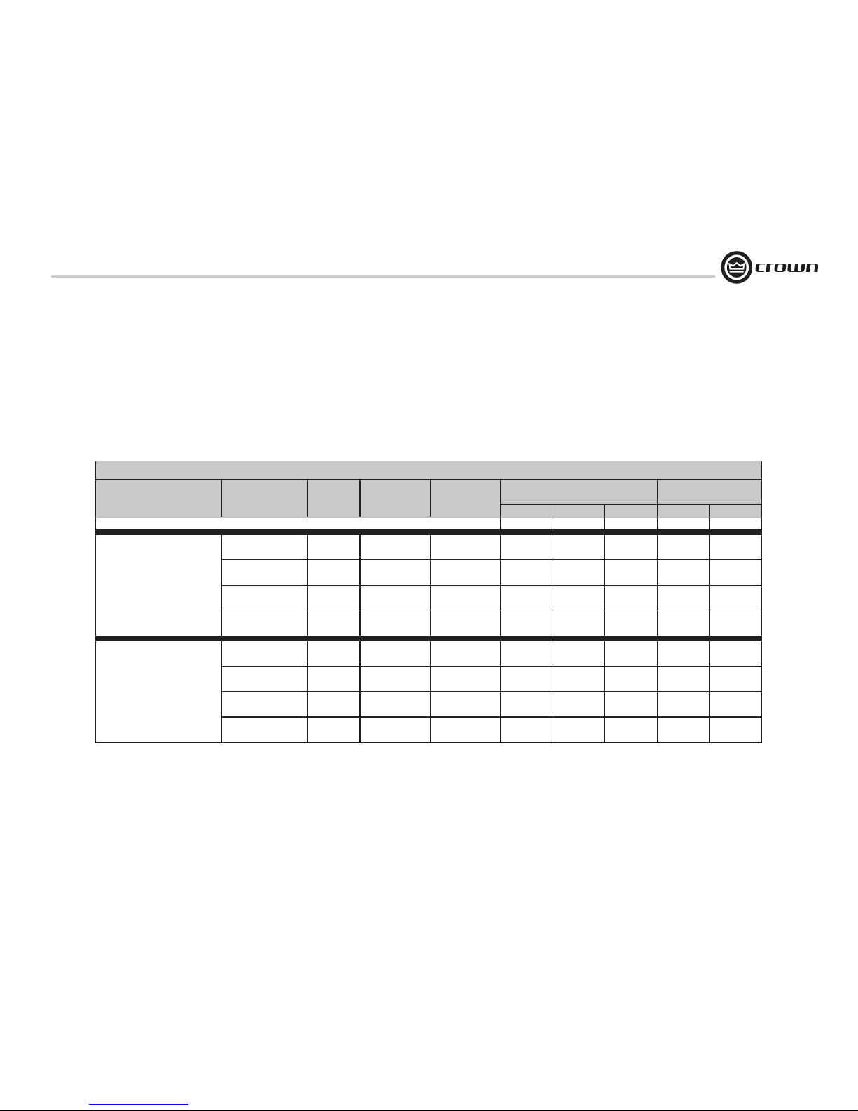
AC Power Draw and Thermal Dissipation:
Pink noise 12dB crest factor, bandwidth limited 22Hz to 22kHz.
Typical line impedance used.
Measurements made with 120VAC mains. Data based on all channels driven.
Line current figures for 230VAC units derived by multiplying 120VAC figures by 0.5.
Line current figures for 100VAC units (not shown) are 1.2 times the line current figures of 120VAC units.
Power draw (”watts in”) of 100VAC units is the same as power draw of 120VAC units.
watts in
watts out dissapated
Btu/hr kcal/hr
At Idle (sleep mode)
40 0 40 137 34
1/8th Power Pink Noise 8 Ohms/Ch.
1000x2
Typical of program material 16 Ohms Bridge
2000
just at clip. 4 Ohms/Ch.
1000x2
8 Ohms Bridge
2000
2 Ohms/Ch.
1000x2
4 Ohms Bridge
2000
70/100V/Ch. 1000x2
140/200V Bridge 2000
1/3rd Power Pink Noise 8 Ohms/Ch.
1000x2
Typical of program material 16 Ohms Bridge
2000
with severe clipping. 4 Ohms/Ch.
1000x2
8 Ohms Bridge
2000
2 Ohms/Ch.
1000x2
4 Ohms Bridge
2000
70/100V/Ch. 1000x2
140/200V Bridge 2000
485 1655 417
11.6 5.8 990 674 316 1080 272
13.7 6.9 1190 705
304 1036 261
12.3 6.2 1064 672 392 1338 337
11.3 5.6 980 676
351 1198 302
6.7 3.4 639 257 382 1304 329
7.2 3.6 602 251
290 988 249
7.0 3.5 563 255 307 1049 264
6.6 3.3 546 256
CTs 2000
Load
Rated
Power
Line Current
120VAC
Line Current
230VAC
Watts
Thermal Dissipation
8 AC Power Draw and Thermal Dissipation
Page 30
Operation Manual
CTs Power Amplifiers
page 30
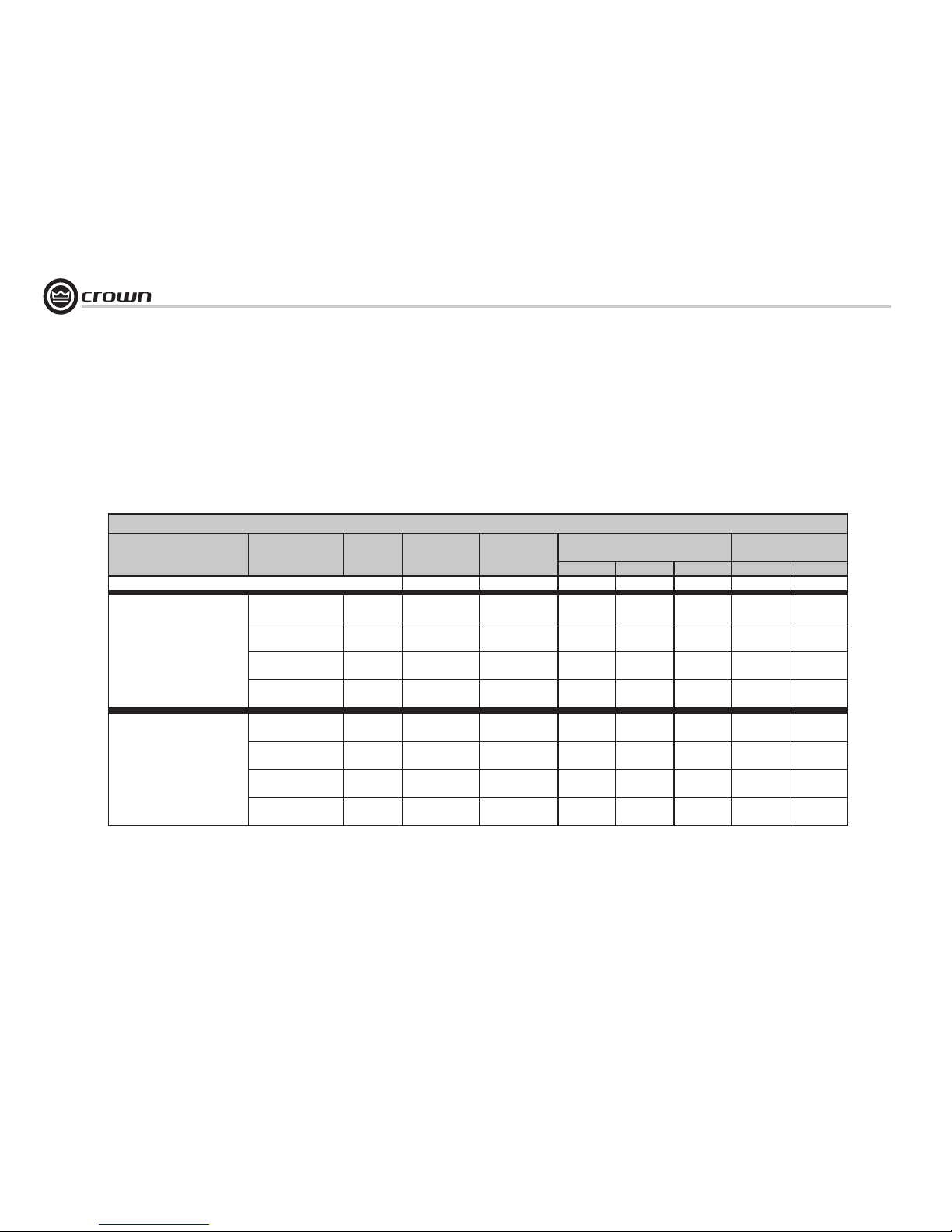
AC Power Draw and Thermal Dissipation:
Pink noise 12dB crest factor, bandwidth limited 22Hz to 22kHz.
Typical line impedance used.
Measurements made with 120VAC mains. Data based on all channels driven.
Line current figures for 230VAC units derived by multiplying 120VAC figures by 0.5.
Line current figures for 100VAC units (not shown) are 1.2 times the line current figures of 120VAC units.
Power draw (”watts in”) of 100VAC units is the same as power draw of 120VAC units.
watts in
watts out dissapated
Btu/hr kcal/hr
At Idle (sleep mode)
40 0 40 137 34
1/8th Power Pink Noise 8 Ohms/Ch.
1000x2
Typical of program material 16 Ohms Bridge
2000
just at clip. 4 Ohms/Ch.
1000x2
8 Ohms Bridge
2000
2 Ohms/Ch.
1000x2
4 Ohms Bridge
2000
70/100V/Ch. 1000x2
140/200V Bridge 2000
1/3rd Power Pink Noise 8 Ohms/Ch.
1250x2
Typical of program material 16 Ohms Bridge
2500
with severe clipping. 4 Ohms/Ch.
1500x2
8 Ohms Bridge
3000
2 Ohms/Ch.
1500x2
4 Ohms Bridge
3000
70/100V/Ch. 1500x2
140/200V Bridge 3000
CTs 3000
Load
Rated
Power
Line Current
120VAC
Line Current
230VAC
Watts
Thermal Dissipation
7.2 3.6 579 313 266 907 229
8.5 4.2 697 381 316 1079 272
9.6 4.8 790 384 405 1384 349
7.2 3.6 579 313 266 907 229
13.7 6.8 1196 835 360 1230 310
16.2 8.1 1469 1010 459 1565 395
19.2 9.6 1686 1024 662 2259 570
13.7 6.8 1196 835 360 1230 310
8 AC Power Draw and Thermal Dissipation
Page 31
page 31
CTs Power Amplifiers
Operation Manual
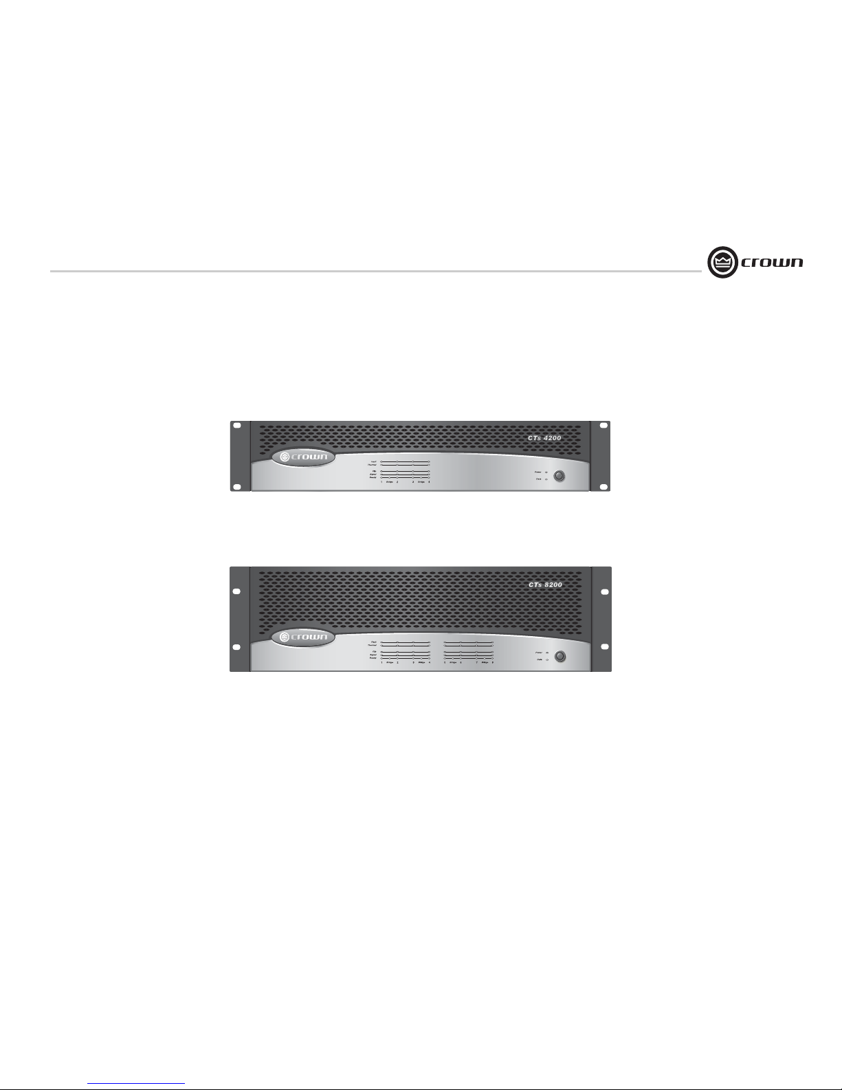
CTs Multi-Channel Series
CTs 8200
CTs 4200
Page 32
Operation Manual
CTs Power Amplifiers
page 32
DECLARATION of CONFORMITY
Crown Audio, Inc.
Sue Whitfield
574-294-8289
[email protected]
European Representative's Name and Address:
David Budge
10 Harvest Close
Yateley GU46 6YS
United Kingdom
Equipment Type: Commercial Audio Power Amplifiers
Family Name: CTs
Model Names: CTs 4200A, CTs 8200A
EMC Standards:
EN 55103-1:1995 Electromagnetic Compatibility - Product Family Standard for Audio, Video, Audio-Visual and Entertainment Lighting Control Apparatus for Professional Use, Part 1: Emissions
EN 55103-1:1995 Magnetic Field Emissions-Annex A @ 10 cm and 1 M
EN 61000-3-2:1995+A14:2000 Limits for Harmonic Current Emissions (equipment input current ≤16A per phase)
EN 61000-3-3:1995 Limitation of Voltage Fluctuations and Flicker in Low-Voltage Supply Systems Rated Current ≤16A
EN 55022:1992 + A1: 1995 & A2:1997 Limits and Methods of Measurement of Radio Disturbance Characteristics of ITE: Radiated, Class B Limits; Conducted, Class B
EN 55103-2:1996 Electromagnetic Compatibility - Product Family Standard for Audio, Video, Audio-Visual and Entertainment Lighting Control Apparatus for Professional Use, Part 2: Immunity
EN 61000-4-2:1995 Electrostatic Discharge Immunity (Environment E2-Criteria B, 4k V Contact, 8k V Air Discharge)
EN 61000-4-3:1996 Radiated, Radio-Frequency, Electromagnetic Immunity (Environment E2, criteria A)
EN 61000-4-4:1995 Electrical Fast Transient/Burst Immunity (Criteria B)
EN 61000-4-5:1995 Surge Immunity (Criteria B)
EN 61000-4-6:1996 Immunity to Conducted Disturbances Induced by Radio-Frequency Fields (Criteria A)
EN 61000-4-11:1994 Voltage Dips, Short Interruptions and Voltage Variation
Safety Standard:
EN 60065: 1998 Safety Requirements - Audio Video and Similar Electronic Apparatus
I certify that the product identified above conforms to the requirements of the EMC Council Directive 89/336/EEC as amended by 92/31/EEC, and the Low Voltage Directive 73/23/EES as amended by 93/68/EEC.
Larry Coburn
Signed
Title: Senior Vice President of Manufacturing
Date of Issue: March 1, 2002
ISSUED BY: Crown Audio, Inc.
1718 W. Mishawaka Road
Elkhart, Indiana 46517 U.S.A.
Due to line current harmonics, we recommend that you contact your supply authority before connection.
FOR COMPLIANCE QUESTIONS ONLY:
Page 33
page 33
CTs Power Amplifiers
Operation Manual
1 Welcome
Building on the foundation of the Com-Tech®
Series, Crown’s CTs Series offers new flexibility
and value for installed sound applications. The
Com-Tech Series were the first to offer independent selection of high- and low-impedance
operation for a specific channel, and CTs Series
amplifiers continue that tradition, with power
levels and features carefully chosen to perfectly
integrate into fixed install design requirements.
Modern power amplifiers are sophisticated
pieces of engineering capable of producing
extremely high power levels. They must be
treated with respect and correctly installed if
they are to provide the many years of reliable
service for which they were designed.
In addition, CTs Series amplifiers include a
number of features which require some explanation before they can be used to their maximum advantage.
Please take the time to study this manual so
that you can obtain the best possible service
from your amplifier.
1.1 Features
•New Crown
®
Switching Power Supply for
reduced weight.
• High power-density, with eight channels in
a 3U chassis and four channels in a 2U
chassis.
• Selectable constant-voltage (70V/100V) or
low-impedance (8/4 ohm) operation for
each channel pair.
• FIT (Fault Isolation Topology) circuitry
isolates faults within affected channels.
• 35 Hz High-Pass Filter (70 Hz in CTs
4200) is automatically inserted when the
channel pair is set for constant-voltage
operation. (corner frequency may be
changed as a service option).
• Accepts VC-MC accessory module that
tailors the amplifier for remote VCA level
control.
• Comprehensive array of indicators including Power and Data, along with Bridge,
Ready, Signal, Clip, Thermal and Fault for
each channel, provide accurate diagnostics.
• Blue Power Indicator flashes if the amplifier shuts off due to an under-/over-voltage
condition on the AC mains.
• Advanced protection circuitry guards
against: shorted outputs, open circuits,
DC, mismatched loads, general overheating, under-/over-voltage, high-frequency
overloads and internal faults.
• Proven Crown AB+B Multi-Mode
®
output
topology.
• Continuously-variable-speed fans optimize cooling efficiency.
• Three Year, No-Fault, Fully-Transferable
Warranty completely protects your investment and guarantees its specifications.
2 How to Use This
Manual
This manual provides you with the necessary
information to safely and correctly setup and
operate your amplifier. It does not cover every
aspect of installation, setup or operation that
might occur under every condition. For additional information, please consult Crown’s
Amplifier Application Guide (available online at
www.crownaudio.com), Crown Tech Support,
your system installer or retailer.
We strongly recommend you read all instructions, warnings and cautions contained in this
manual. Also, for your protection, please send
in your warranty registration card today, or register online at www.crownaudio.com. And save
your bill of sale—it’s your official proof of purchase.
4-ohm (per ch.)
8-ohm (per ch.)
70V (per ch.)
1 kHz
CTs 4200
20 Hz–20 kHz
Dual
4 Channels Driven
260W
180W
220W
215W
190W
220W
*
*
4-ohm (per ch.)
8-ohm (per ch.)
70V (per ch.)
1 kHz 20 Hz–20 kHz1 Channel Driven
270W
220W
250W
225W
210W
245W
8-ohm (per ch. pair)
16-ohm (per ch. pair)
100V (per ch. pair)
1 kHz 20 Hz–20 kHz
Bridge-Mono
2 Channel-Pairs Driven
520W
400W
220W
430W
380W
220W
*
*
8-ohm (per ch. pair)
16-ohm (per ch. pair)
100V (per ch. pair)
1 kHz 20 Hz–20 kHz1 Channel-Pair Driven
560W
440W
250W
450W
420W
245W
Maximum Average Power
in watts with 0.1% THD.
*
Constant Voltage full bandwidth power ratings support
100Hz - 20kHz due to automatic High-Pass Filters.
4-ohm (per ch.)
8-ohm (per ch.)
70V (per ch.)
1 kHz
CTs 8200
20 Hz–20 kHz
Dual
8 Channels Driven
200W
160W
200W
175W
155W
185W
*
*
4-ohm (per ch.)
8-ohm (per ch.)
70V (per ch.)
1 kHz 20 Hz–20 kHz1 Channel Driven
270W
220W
250W
230W
220W
230W
8-ohm (per ch. pair)
16-ohm (per ch. pair)
100V (per ch. pair)
1 kHz 20 Hz–20 kHz
Bridge-Mono
4 Channel-Pairs Driven
400W
320W
200W
350W
310W
185W
*
*
8-ohm (per ch. pair)
16-ohm (per ch. pair)
100V (per ch. pair)
1 kHz 20 Hz–20 kHz1 Channel-Pair Driven
540W
440W
250W
460W
440W
230W
Maximum Average Power
in watts with 0.1% THD.
*
Constant Voltage full bandwidth power ratings support
100Hz - 20kHz due to automatic High-Pass Filters.
Page 34
Operation Manual
CTs Power Amplifiers
page 34
Power
Data
12
Bridge34Bridge
Fault
Thermal
Clip
Signal
Ready
3.1 Unpack Your Amplifier
Please unpack and inspect your amplifier for
any damage that may have occurred during
transit. If damage is found, notify the transportation company immediately. Only you can initiate a claim for shipping damage. Crown will
be happy to help as needed. Save the shipping
carton as evidence of damage for the shipper’s
inspection.
We also recommend that you save all packing
materials so you will have them if you ever
need to transport the unit. Never ship the
unit without the factory pack.
YOU WILL NEED (not supplied):
• Input wiring cables
• Output wiring cables
Rack for mounting amplifier (or a stable surface
for stacking)
WARNING: Before you start to set up
your amplifier, make sure you read and
observe the Important Safety Instructions found at the beginning of this
manual.
3.2 Install Your Amplifier
CAUTION: Before you begin, make sure
your amplifier is disconnected from the
power source, with the power switch in
the “off” position and all level controls
turned completely down (counterclockwise).
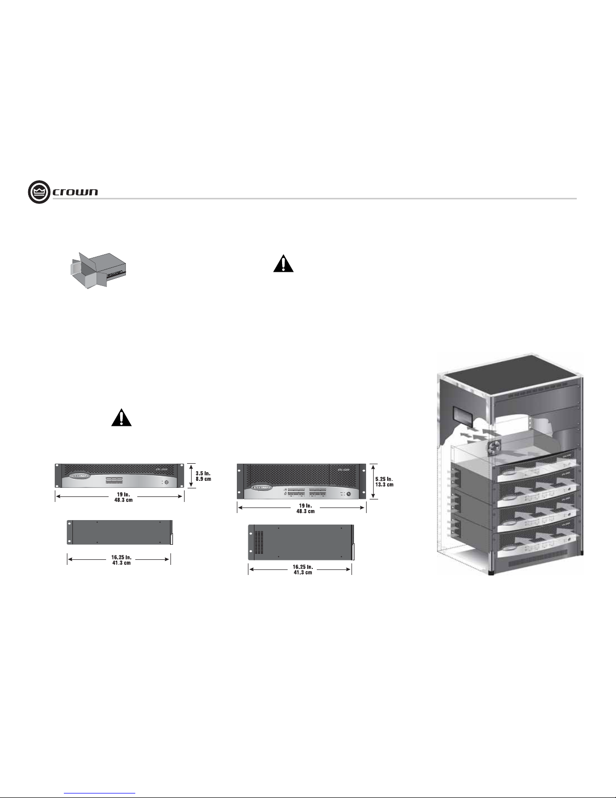
Use a standard 19-inch (48.3-cm) equipment
rack (EIA RS-310B). See Figure 3.1 for amplifier dimensions.
You may also stack amps without using a
cabinet.
NOTE: When transporting, amplifiers should be
supported at both front and back.
3.3 Ensure Proper Cooling
When using an equipment rack, mount units
directly on top of each other. Close any open
spaces in rack with blank panels. DO NOT
block front, rear or side air vents. The side
walls of the rack should be a minimum of two
inches (5.1 cm) away from the amplifier sides,
and the back of the rack should be a minimum
of four inches (10.2 cm) from the amplifier back
panel.
Figure 3.2 illustrates standard amplifier airflow.
3 Setup
Figure 3.1 Dimensions
Left: CTs 4200 Right: CTs 8200
Figure 3.2 Airflow
Page 35
page 35
CTs Power Amplifiers
Operation Manual
3.4 Choose Input Wire
and Connectors
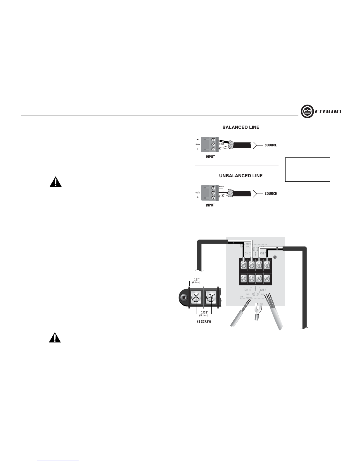
Figure 3.3 shows connector pin assignments for balanced wiring, and Figure
3.4 shows connector pin assignments for unbalanced wiring.
When possible, use balanced wiring for signal input, which provides better
rejection of unwanted noise and hum. For more information, refer to the
Crown Amplifier Application Guide, available online at www.crownaudio.com
NOTE: Custom wiring should only be performed by qualified personnel.
Figure 3.3 Balanced Input
Connector Wiring
Figure 3.4 Unbalanced Input
Connector Wiring
3 Setup
3.5 Choose Output Wire and
Connectors
Crown recommends using professionally constructed, highquality, two- or four-conductor, heavy gauge speaker wire and connectors.
You may use terminal forks or bare wire for your output connectors (see Figure 3.5). CTs amplifier terminal strips accept up to 10 AWG terminal forks
which fit over a #8 screw. For best results, Crown recommends Panduit part
#PV10-10LF-L or equivalent terminal fork. Screw spacing is shown in Figure
3.5.
To connect outputs, first remove the touch-proof cover plate covering the ter-
minal strip by removing the screw which holds it in place.
To prevent the possibility of short-circuits, wrap or otherwise insulate exposed
loudspeaker cable and connectors. Also, a touch-proof cover plate, which
covers the terminal strips, is provided to help prevent short circuits. The cover
plate should be reinstalled after connecting outputs.
Suggested below are guidelines to select the appropriate size of wire based on
the distance from amplifier to speaker. Check with local code as this may vary.
Distance Wire Size
up to 25 ft (7.6 m) 16 AWG
26-40 ft (7.9-12.2 m) 14 AWG
41-60 ft (12.5-18.3 m) 12 AWG
Over 60 ft (18.3 m) 10 AWG
CAUTION: Never connect the speaker return to the chassis of the
amplifier, or damage to the amplifier may result.
CAUTION: Never use shielded cable for output wiring.
Figure 3.5 Output Connector Wiring
(Typical of two channels)
See the Crown Amplifier Application Guide, available online at
www.crownaudio.com, for pin
assignments for commonly
used connector types.
Output panel
shown with
touch-proof
cover plate
removed.
NOTE: CTs 8200 is shown. Some CTs 4200 features are in different locations.
Page 36
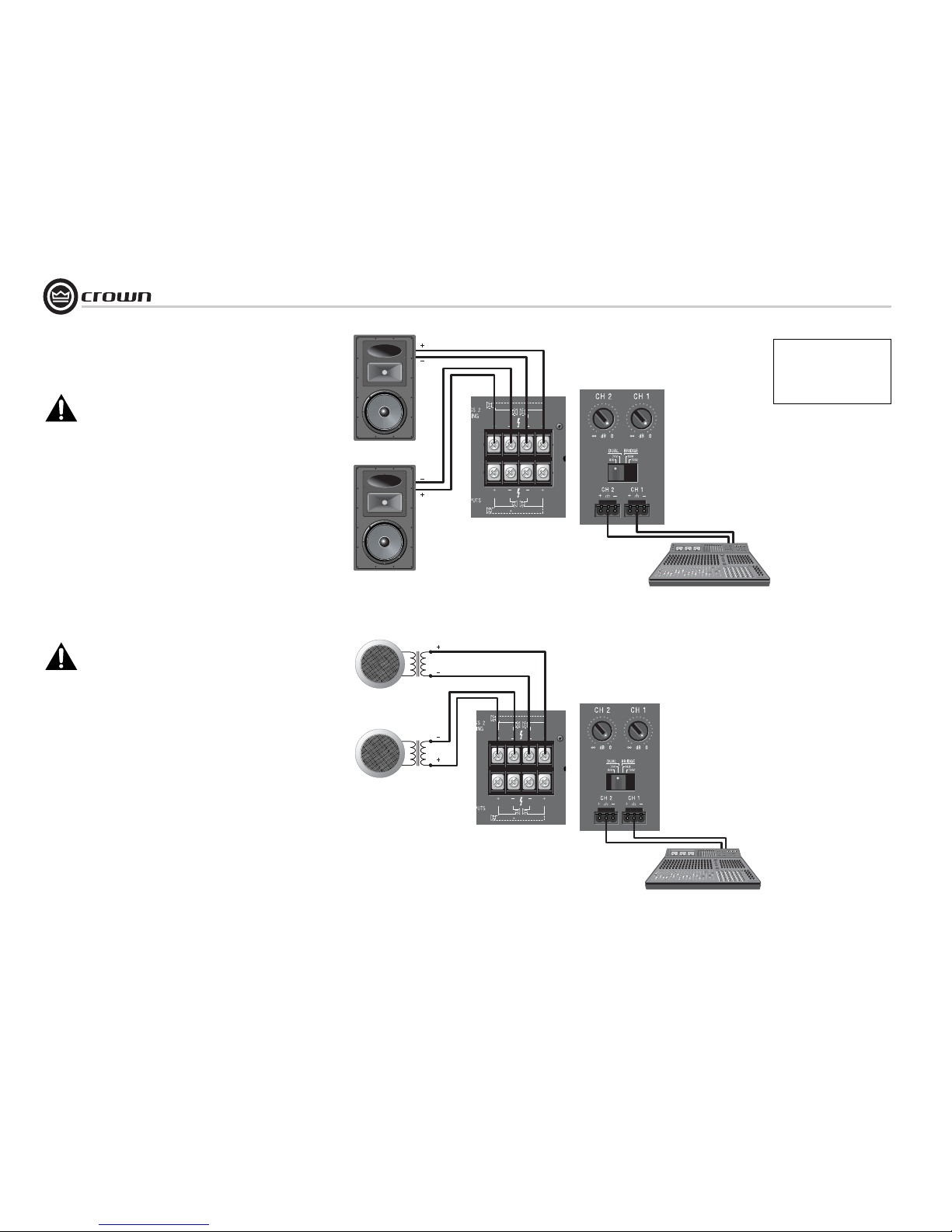
Operation Manual
CTs Power Amplifiers
page 36
3.6 Wire Your System
CAUTION: Never change the position of
the Mode Switch while the amplifier
power is on. See Section 5.2.2 for more
information.
3.6.1 Dual 8/4 Mode
Typical input and output wiring, along with level
control and Mode Switch settings are shown in
Figure 3.6. Make sure the Mode switch is set to
the “Dual 8/4” position.
INPUTS: Connect input wiring for each channel.
OUTPUTS: Maintain proper polarity (+/–) on
output connectors.
Connect the Channel 1 speaker’s positive (+)
lead to amplifier Channel 1 positive terminal;
repeat for negative (–). Repeat each channel wiring as for Channel 1. Refer to Section 3.5 for
output connector pin assignments.
3.6.2 Dual 70V Mode
CAUTION: Never change the position of
the Mode Switch while the amplifier
power is on. See Section 5.2.2 for more
information.
Typical input and output wiring, along with level
control and Mode Switch settings are shown in
Figure 3.7. Make sure the Mode switch is set to
the “Dual 70V” position.
INPUTS: Connect input wiring for each channel.
OUTPUTS: Maintain proper polarity (+/–) on
output connectors.
Connect Channel 1 positive (+) speaker load to
Channel 1 positive terminal of amp; repeat for
negative (–). Repeat each channel wiring as for
Channel 1. Refer to Section 3.5 for output connector pin assignments.
3 Setup
Figure 3.6 System Wiring and Control Settings, Dual Mode, 8/4 Ohm
Figure 3.7 System Wiring and Control Settings, Dual Mode, 70V.
Output panel
shown with
touch-proof
cover plate
removed.
Output panel
shown with
touch-proof
cover plate
removed.
CH 4
DUAL DUAL
BRIDGE
CH 3
CH 2
DUAL DUAL
BRIDGE
CH 1
See the Crown Amplifier Application Guide, available online at
www.crownaudio.com, for pin
assignments for commonly
used connector types.
CH 4
DUAL DUAL
BRIDGE
CH 3
CH 2
DUAL DUAL
BRIDGE
CH 1
70V
70V
Page 37
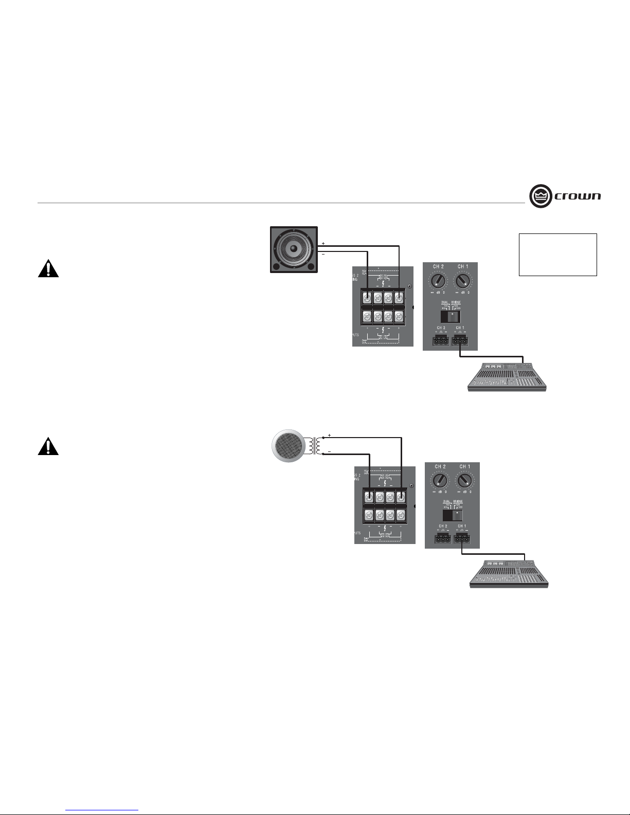
page 37
CTs Power Amplifiers
Operation Manual
3.6.3 Bridge-Mono 16/8 Mode
CAUTION: Never change the position of
the Mode Switch while the amplifier
power is on. See Section 5.2.2 for more
information.
Typical input and output wiring, along with level
control and Mode Switch settings are shown in
Figure 3.8. Make sure the Mode switch is set to
the “Bridge 16/8” position.
INPUTS: Connect input wiring only to the lower(odd-) numbered channel pair.
OUTPUTS: Connect the speaker across the positive terminals of each channel pair. Do not use
the negative terminals of the channel pair when
the pair is being operated in Bridge-Mono mode.
NOTE: When operating the channel pair in
Bridge-Mono mode, turn down (full CCW) the
level control for the higher (even)-numbered
channel of the channel pair. The lower (odd)numbered level control works both channels.
3.6.4 Bridge-Mono 100V Mode
CAUTION: Never change the position of
the Mode Switch while the amplifier
power is on. See Section 5.2.2 for more
information.
Typical input and output wiring, along with level
control and Mode Switch settings are shown in
Figure 3.9. Make sure the Mode switch is set to
the “Bridge 100V” position.
INPUTS: Connect input wiring only to the lower(odd-) numbered channel pair.
OUTPUTS: Connect the speaker across the positive terminals of each channel pair. Do not use
the negative terminals of the channel pair when
the pair is being operated in Bridge-Mono mode.
NOTE: When operating the channel pair in
Bridge-Mono mode, turn down (full CCW) the
level control for the higher (even)-numbered
channel of the channel pair. The lower (odd)numbered level control works both channels.
3 Setup
Figure 3.8 System Wiring and Control Settings, Bridge-Mono Mode, 16/8 Ohm.
Figure 3.9 System Wiring and Control Settings, Bridge-Mono Mode, 100V
CH 4
DUAL DUAL
BRIDGE
CH 3
CH 2
DUAL DUAL
BRIDGE
CH 1
See the Crown Amplifier Application Guide, available online at
www.crownaudio.com, for pin
assignments for commonly
used connector types.
CH 4
DUAL DUAL
BRIDGE
CH 3
CH 2
DUAL DUAL
BRIDGE
CH 1
100V
Page 38
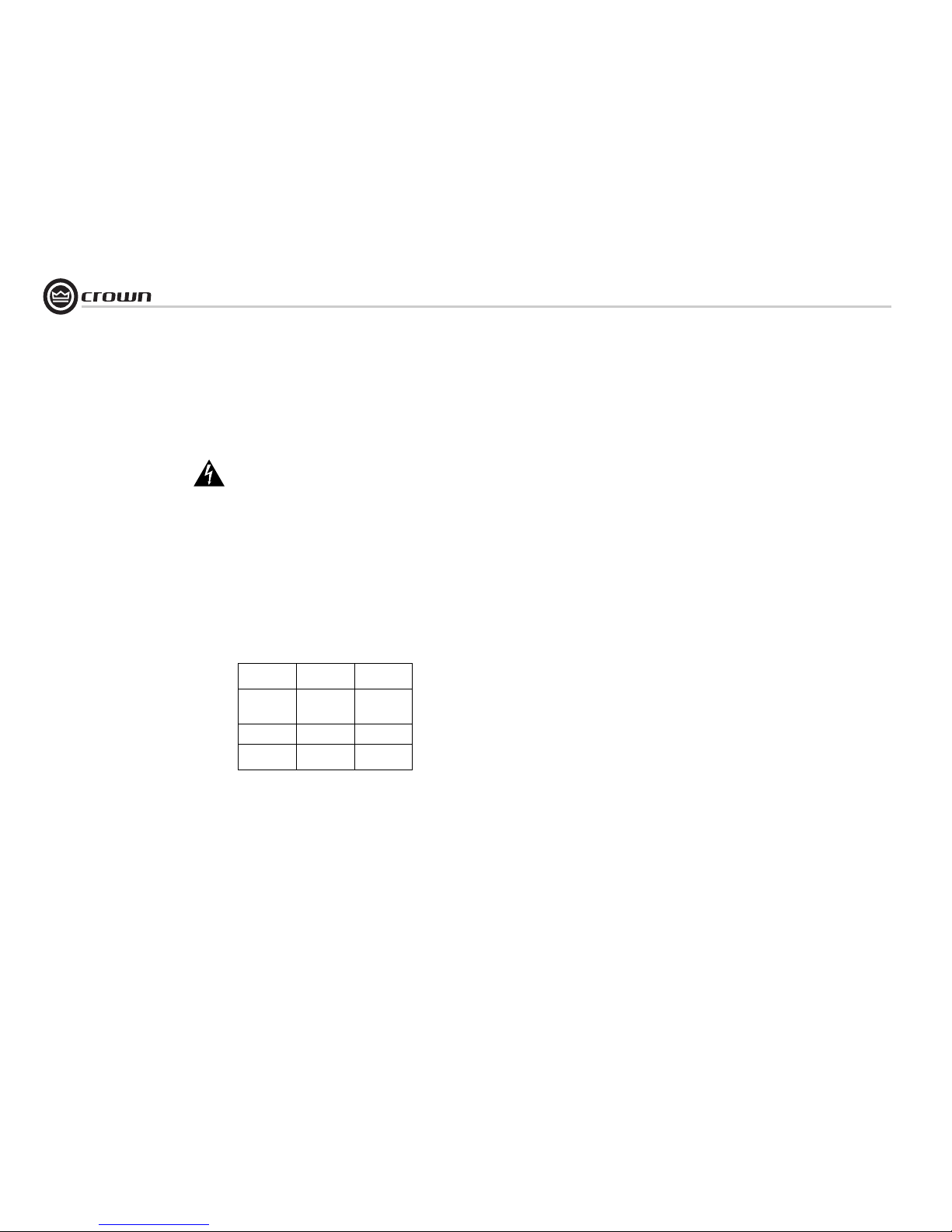
Operation Manual
CTs Power Amplifiers
page 38
3.7 Connect to AC Mains
Connect your amplifier to the AC mains power
source (power outlet) with the supplied AC power
cordset. First, connect the IEC end of the cordset to
the IEC connector on the amplifier; then, plug the
other end of the cordset to the AC mains.
WARNING: The third prong of this connector
(ground) is an important safety feature. Do
not attempt to disable this ground connection by using an adapter or other methods.
Amplifiers don’t create energy. The AC mains voltage and current must be sufficient to deliver the
power you expect. If the AC line voltage varies out
of an acceptable range, the amplifier’s power supply
turns off and the blue Power LED flashes. The
amplifier will turn back on when the AC line voltage
returns to safe operating levels. Figure 3.10 provides voltage limits for all amplifier AC voltage configurations. Also, the amplifier must be run within
the specified mains frequency requirements (indicated on the amplifier’s back panel label). If you are
unsure of the output voltage of your AC mains,
please consult your electrician.
Models
Under-Voltage
Limit
Over-Voltage
Limit
100VAC
(CTs 8200
only)
90VAC 110VAC
120 VAC units 108VAC 132VAC
220V/230V/
240V units
198VAC 264VAC
3.8 Startup Procedure
Use the following procedure when first turning on
your amplifier:
1. Turn down the level of your audio source.
2. Turn down the level controls of the amplifier.
3. Turn on the “Power” switch. The Power indicator should glow.
4. Turn up the level of your audio source to an
optimum level.
5. Turn up the Level controls on the amplifier until
the desired loudness or power level is
achieved.
6. Turn down the level of your audio source to its
normal range.
If you ever need to make any wiring or installation
changes, don’t forget to disconnect the power cord.
For help with determining your system’s optimum
gain structure (signal levels) please refer to the
Crown Amplifier Application Guide, available online
at www.crownaudio.com.
3 Setup
Figure 3.10 AC Under-Voltage and Over-Voltage
Limits for Various Amplifier Models
Page 39

page 39
CTs Power Amplifiers
Operation Manual
4. WARNING: Never connect the output
to a power supply, battery or power
main. Electrical shock may result.
5. Tampering with the circuitry, or making
unauthorized circuit changes may be hazardous and invalidates all agency listings, and
may also void the product’s warranty.
6. Do not operate the amplifier with the red Clip
LEDs constantly flashing.
7. Do not overdrive the mixer, which will cause
clipped signal to be sent to the amplifier.
Such signals will be reproduced with
extreme accuracy, and loudspeaker damage
may result.
8. Use caution when operating the amplifier
with a 2-ohm load impedance on 1 channel.
Do not operate the amplifier with less than a
2-ohm load impedance per channel when
driving more than 1 channel. Due to the
amplifier’s output protection, such a configuration may result in premature clipping,
speaker damage or a blown power fuse.
Remember: Crown is not liable for damage that
results from overdriving other system components.
4.1 Precautions
Your amplifier is protected from internal and
external faults, but you should still take the following precautions for optimum performance and
safety:
1. Before use, your amplifier first must be configured for proper operation, including input
and output wiring hookup. Improper wiring
can result in serious operating difficulties.
For information on wiring and configuration,
please consult the Setup section of this
manual or, for advanced setup techniques,
consult Crown’s Amplifier Application Guide
available online at www.crownaudio.com.
2. Use care when making connections, selecting signal sources and controlling the output level. The load you save may be your
own!
3. Do not short the ground lead of an output
cable to the input signal ground. This may
form a ground loop and cause oscillations.
4 Operation
Page 40
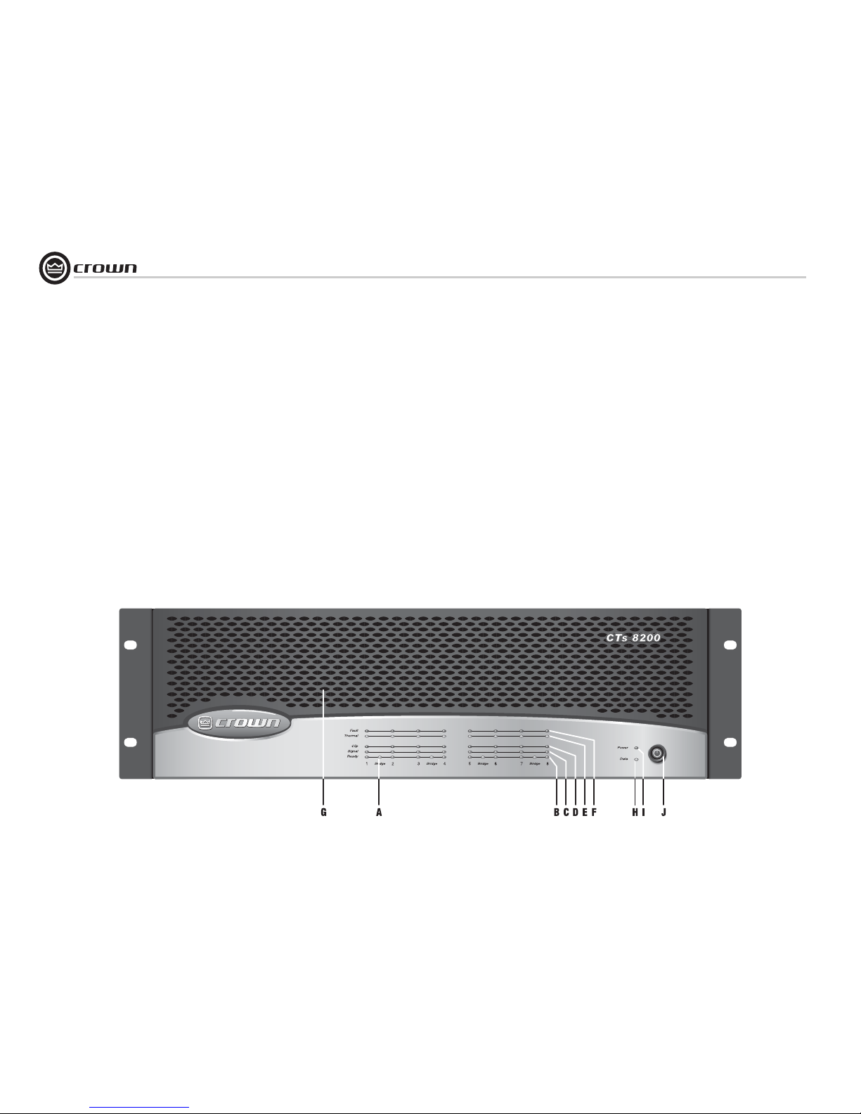
Operation Manual
CTs Power Amplifiers
page 40
4.2 Front Panel Controls
and Indicators
Note: CTs 8200 is shown. Some CTs
4200 features are in different locations.
A. Bridge Mode Indicator
Yellow LED, one per channel pair, illuminates when the channel pair's Mode
Switch is set to the “Bridge” position. If
Mode switch is changed while amplifier is
powered up, Bridge LED will flash, indicating that the amplifier must be powered off
and on to reset the Mode. See Section 6.9.
B. Ready Indicator
Green LED, one per channel, illuminates
when the channel is initialized and ready to
produce audio output.
C. Signal Indicator
Green LED, one per channel, illuminates to
indicate the presence of input signals
above –40 dBu.
D. Clip Indicator
Red LED, one per channel, illuminates
when the THD of the channel’s output signal rises to a level typically considered as
the onset of audible clipping. The Clip
Indicator also will illuminate during Thermal Level Control (TLC) or input overload.
E. Thermal Indicator
Red LED, one per channel, flashes when
the channel has shut down due to thermal
stress or overload. If the power supply
goes into thermal overload, all channel
LEDs will flash.
F. Fault Indicator
Red LED, one per channel, illuminates
when the amplifier output channel has
stopped operating.
G. Ventilation Grille
Front-to-rear forced airflow.
H. Data Indicator
Yellow LED indicates IQ Loop data activity
(if the amplifier is equipped with an IQ-MC
module, and connected to an IQ Loop).
I. Power Indicator
Blue LED indicates amplifier has been
turned on and AC power is available. Indicator also flashes if the amplifier shuts off
due to an under/over-voltage condition on
the AC mains.
J. Power Switch
Amplifier is on when the switch is in the IN
position.
Figure 4.1 CTs 8200 front panel.
4 Operation
Page 41
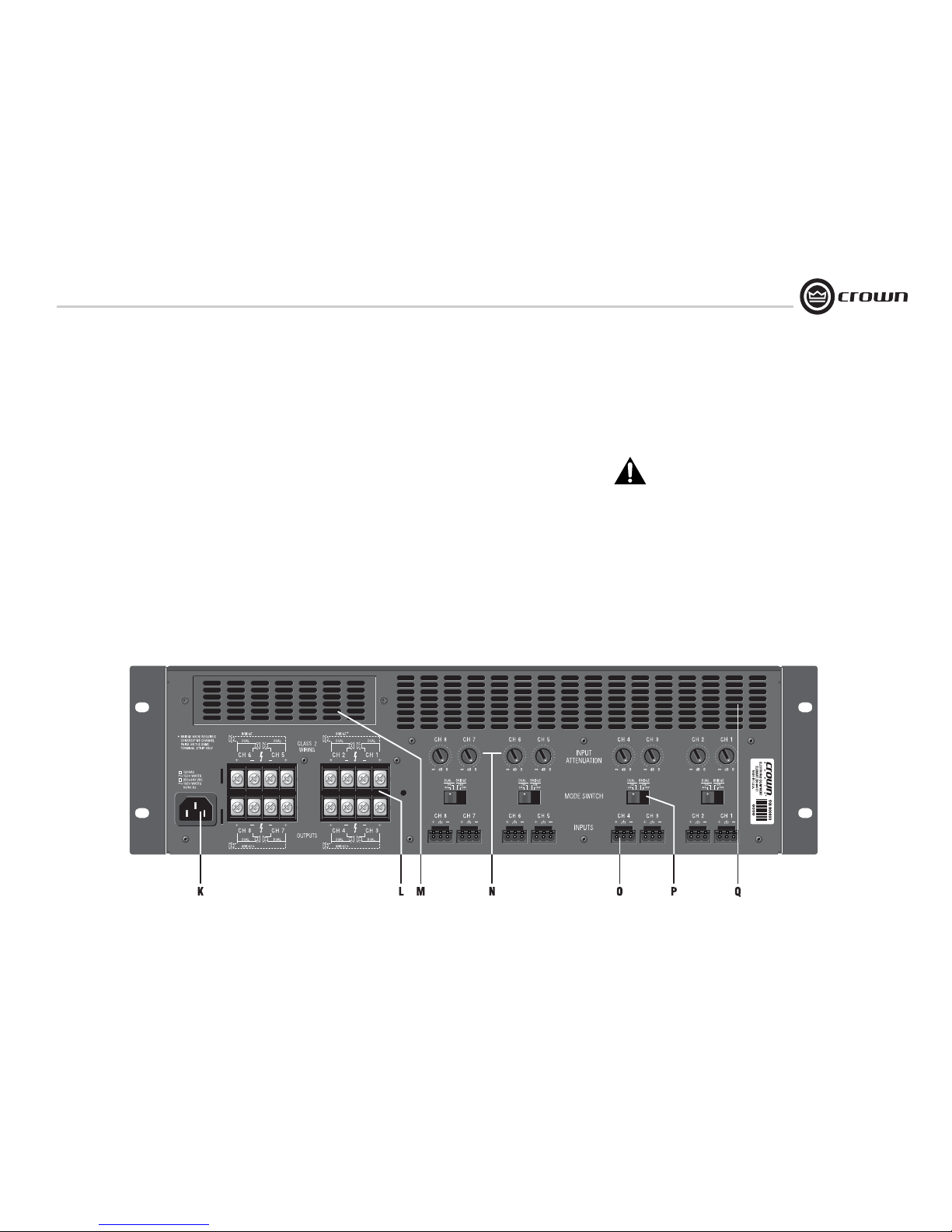
page 41
CTs Power Amplifiers
Operation Manual
4.3 Back Panel Controls
and Connectors
Note: CTs 8200 is shown. Some CTs
4200 features are in different locations.
K. AC Power Cord Connector
Standard IEC type 320 inlet.
120V models: 15-amp.
220-240V models: 10-amp.
Voltage is indicated above IEC inlet.
L. Output Connectors
One four-pole terminal strip for every two channels with touch-proof cover. Accepts up to 10
AWG terminal forks. To connect outputs, first
remove the touch-proof cover plate covering
the terminal strip by removing the screw which
holds it in place.
M. Accessory Panel
CTs 4200: Accepts an optional IQ-MC4A or
VCA-MC4A module.
CTs 8200: Accepts an optional IQ-MC8 or
VCA-MC8 module (explained in Section 5.3.1,
Control Modules).
N. Channel Level Controls
One 21-position detented rotary potentiometer
per channel, ranging from infinity (-70 dB) to
0 dB attenuation. Refer to Section 5.2.4 for precise dB attenuation increments for each detent.
O. Input Connectors
Removable Phoenix-style barrier connectors
for balanced input.
P. Mode Switch
Used on each consecutive pair of channels, this
four-position switch is used to select the amplifier’s mode of operation: Dual 8/4 ohms,
Dual 70V, Bridge-Mono 16/8 ohms, and
Bridge-Mono 100V.
IMPORTANT: Be sure to power off the
amplifier before change the Modeswitch setting. If this is not done, the Bridge
light will flash to indicate that the power must
be cycled off and back on to reset the mode.
Q. Cooling Vents
Front-to-rear forced airflow.
4 Operation
Figure 4.2 CTs 8200 back panel (shown with touch-proof cover removed).
Page 42
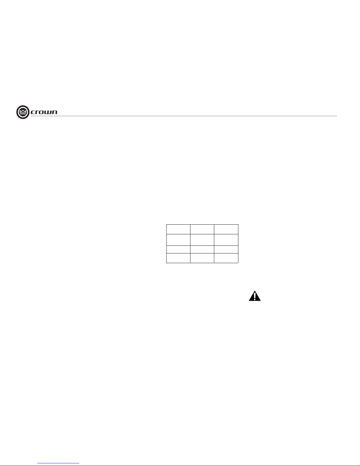
Operation Manual
CTs Power Amplifiers
page 42
NOTE: For more information about these Crown
amplifier features, please visit the Crown website at www.crownaudio.com.
5.1 Protection Systems
Your Crown amplifier provides extensive protection and
diagnostic capabilities, including thermal level control,
fault indicators, automatic high-pass filtering, DC protect, AC under-/over-voltage protection, inrush limiting,
and variable-speed fans.
5.1.1 Thermal Level Control (TLC)
If an amplifier channel starts to overheat, the TLC circuit
will engage that channel’s input compressor. By compressing the input, the amplifier will not generate as
much heat and will have a chance to cool down. The
degree of compression is proportional to the amount of
overheating. If the channel becomes too hot for safe
operation even after full TLC limiting, the channel will
shut off, and the Thermal Indicator for that channel will
flash brightly to alert the user that a state of thermal
stress or overload has cause the channel to shut down.
5.1.2 Fault
If an amplifier channel requires service, the corresponding Fault indicator will illuminate to alert the user of this
condition. If this occurs, return the amplifier to the Cro wn
factory or to an authorized Crown service center.
5.1.3 Fault Isolation Topology (FIT)
Crown’s new FIT (Fault Isolation Topology) design isolates channel-specific faults, and prevents them from
affecting remaining channels. If a CTs multi-channel amp
is powering multiple zones, and a channel fails, the other
zones continue to operate. FIT makes the CTs 4200 and
CTs 8200 the most trustworthy multi-channel amplifiers
in the business!
5.1.4 35-Hz High-Pass Filter
A fixed 35-Hz (70-Hz in CTs 4200) high-pass filter per
channel pair is automatically inserted when the mode
switch is set to either of the constant-voltage settings.
The high-pass filter corner frequency can be set to 70 Hz,
or bypassed, with a service option.
5.1.5 AC Under-/Over-Voltage
Protection
If the AC line voltage varies out of an acceptable range,
the amplifier’s power supply turns off and the blue Power
LED flashes. The amplifier will turn back on when the AC
line voltage returns to safe operating levels. Figure 5.1
provides voltage limits for all amplifier AC voltage configurations. Also, the amplifier must be run within the
specified mains frequency requirements (indicated on the
amplifier’s back panel label). If you are unsure of the output voltage of your AC mains, consult your electrician.
5.1.6 Power Fuse
A fuse protects the amplifier from excessive AC current
draw.
5.1.7 Inrush Limiting
A soft-start circuit in the power supply minimizes the
amplifier’s current draw during power-on.
5.1.8 Variable-speed Fans
Continuously variable speed fans direct the airflow
through the amplifier for cooling.
Models
Under-Voltage
Limit
Over-Voltage
Limit
100VAC
(CTs 8200 only)
90VAC 110VAC
120 VAC units 108VAC 132VAC
220V/230V/
240V units
198VAC 264VAC
5.2 Advanced Features
5.2.1 Switching Power Supply
Crown’s new Switching Power Supply minimizes the
amplifier’s weight.
Typical non-switching power supplies require large,
heavy transformers in order to produce the required
power at the output stage. These transformers must be
large to absorb the substantial waste that occurs when
operating at 50 to 60 Hz (standard AC supplied by the
power company).
By contrast, switching power supplies can operate with a
much smaller (and lighter) transformer because they first
convert the AC up to a much higher frequency, thereby
reducing waste.
The power supply is voltage-specific, allowing use in
regions using 120V/60Hz, 220V/50Hz, 230V/50Hz,
240V/50Hz, and 100V/50Hz AC mains.
5.2.2 Mode Switch
Each consecutive pair of channels has one four-position
switch that selects the amplifier’s mode of operation. The
switch positions are:
• Dual mode for 4 or 8 ohm operation.
• Dual mode for 70V constant-voltage operation.
• Bridge-Mono mode for 8 or 16 ohm operation.
• Bridge-Mono mode for 100V constant-voltage
operation.
Be sure to turn off the amplifier before changing
the Mode-switch setting.
5.2.3 Bridge Mode Indicator
This yellow LED indicates when the amplifier’s mode
switch is set to the Bridge position. Each consecutive pair
of channels has one Bridge LED.
5 Advanced Features
and Options
Figure 5.1 AC Under-Voltage and
Over-Voltage Limits for Various Amplifier
Models
Page 43
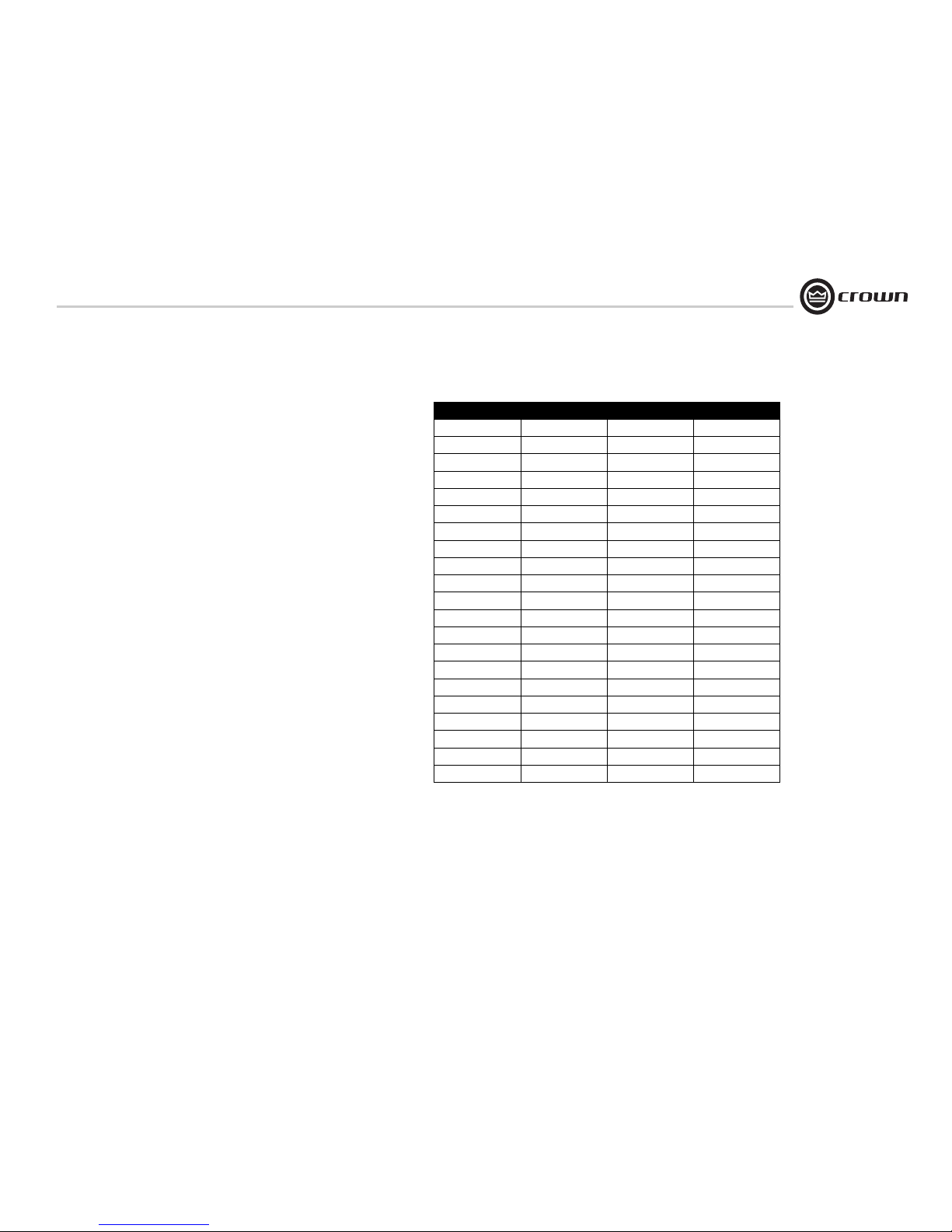
page 43
CTs Power Amplifiers
Operation Manual
5.2.4 Channel Level Control
The signal level for each input can be attenuated accurately by adjusting the 21-step Level
Control (see Section 4.2). Figure 5.2 shows the
amount of attenuation in dB for each detent.
Note: Attenuation per detent varies with operating mode since gain varies with operating
mode. Attenuation amounts shown may vary
±6%.
Detent 4/8 Ohm 70V 100V
0 (full CCW) 68.31 72.90 71.02
1 67.54 72.06 70.26
2 32.23 36.61 34.90
3 25.46 29.74 28.00
4 21.83 25.87 24.22
5 19.23 23.20 21.58
6 17.12 20.94 19.40
7 15.36 19.02 17.53
8 13.76 17.22 15.79
9 12.28 15.53 14.20
10 10.84 13.90 12.62
11 9.51 12.32 11.16
12 8.28 10.87 9.81
13 7.09 9.45 8.45
14 6.30 8.11 7.22
15 4.92 6.70 5.94
16 3.82 5.26 4.63
17 2.62 3.70 3.21
18 1.35 1.90 1.66
19 0.01 0.01 0.01
20 (full CW) 0.00 0.00 0.00
ATTENUATION in dB
Figure 5.2 Level-control Attenuation per Detent in CTs Multichannel Amplifiers
5 Advanced Features
and Options
Page 44
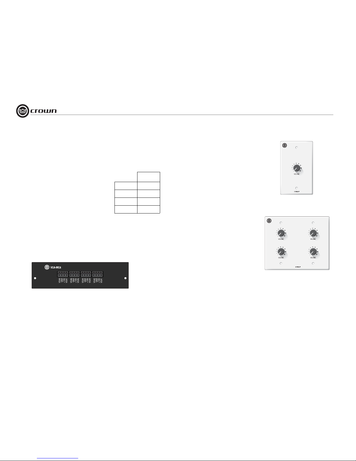
Operation Manual
CTs Power Amplifiers
page 44
Choosing the Right Module
To order accessory modules for your amplifier,
please refer to the model tag (located on the back
panel of the amplifier) for your amplifier’s specific
model number. Then refer to the chart below to
select the correct accessory for your requirements.
VCA MODULE
CTs 4200 VCA-MC4
CTs 4200A VCA-MC4A
CTs 8200 VCA-MC8
CTs 8200A VCA-MC8
Wall-Mount level control panels for use with
VCA module:
1-VCAP: See Figure 5.4. Used in conjunction with
a VCA-MC module, this is a single-gang panel providing remote volume control for one or more CTs
amplifier channels. The potentiometer on the panel
is wired directly to one of the VCA connectors on
the VCA-MC.
4-VCAP: See Figure 5.5. This is a two-gang panel
providing remote volume control for four or more
CTs amplifier channels. The potentiometers on the
panel are wired directly to the respective VCA connector on the VCA-MC.
Refer to the VCA-MC Operation Manual for wiring
of the single or multiple channel level control.
Your amplifier may have come with a VCA-MC
module already factory-installed, or your choice of
MC modules can be easily added to the amplifier by
any authorized Crown Service Center. Contact
Crown Technical Support for more details.
5.3.2 Input Sensitivity
The CTs 4200 and CTs 8200 have a fixed input sensitivity of 1.4V. A service option is available for
other input sensitivities.
Figure 5.3 VCA-MC8 Module
Figure 5.5 4-VCAP Module
5 Advanced Features
and Options
Figure 5.4 1-VCAP Module
5.3 Options
Below are some available options. For current
options, visit the Crown website at www.crownaudio.com.
5.3.1 Control Modules
VCA-MC (VCA module): See Figure 5.3. Provides independent remote level control for each
channel. 4-pin removable Phoenix-style barrier
connectors provide the +10VDC control voltage,
ground, and control lines for two amplifier channels. Thus, 4-channel amplifiers use two connectors; 8-channel amplifiers use four connectors.
Page 45
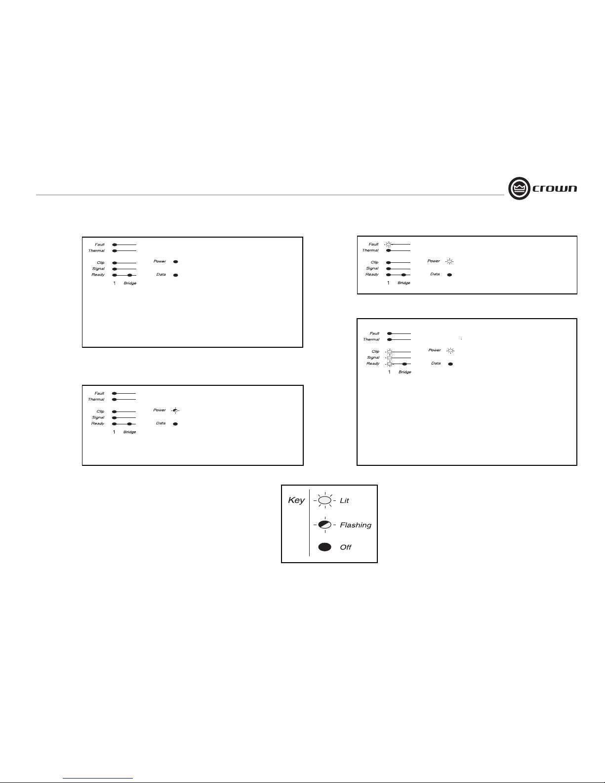
page 45
CTs Power Amplifiers
Operation Manual
CONDITION: Power indicator is off.
POSSIBLE REASON
• The amplifier has lost AC power.
• The amplifier’s Power switch is off.
• The amplifier is not plugged into the
power receptacle.
• The amplifier output level is so high that
the power supply fuse has blown. Verify
that input levels and output impedances
are within safe ranges. Refer the unit to
an authorized Crown service center for
fuse replacement.
CONDITION: Power indicator is
flashing.
POSSIBLE REASON:
• The AC line voltage has dropped below
10% or has risen above 10% of the
nominal line voltage of the power supply.
Refer to section 5.1.6 for specific voltage
requirements.
CONDITION: Fault indicator is on.
POSSIBLE REASON:
• The amplifier channel has stopped operating. Return the unit to an authorized
Crown Service Center.
CONDITION: Distorted sound.
POSSIBLE REASON:
• Load is wired incorrectly or Dual/Bridge
mode switch is set incorrectly. Check
both.
• Input is overloaded by a signal level that
is too high. Turn down your amplifier
level controls, or turn down the input signal, until the clip light goes out.
• Thermal Level Control (TLC) is active.
Note: If the signal sounds distorted even
though the Clip LED is off, the input signal is
distorted. Check gain staging and output levels of the mixer or preamp.
6 Troubleshooting
Page 46
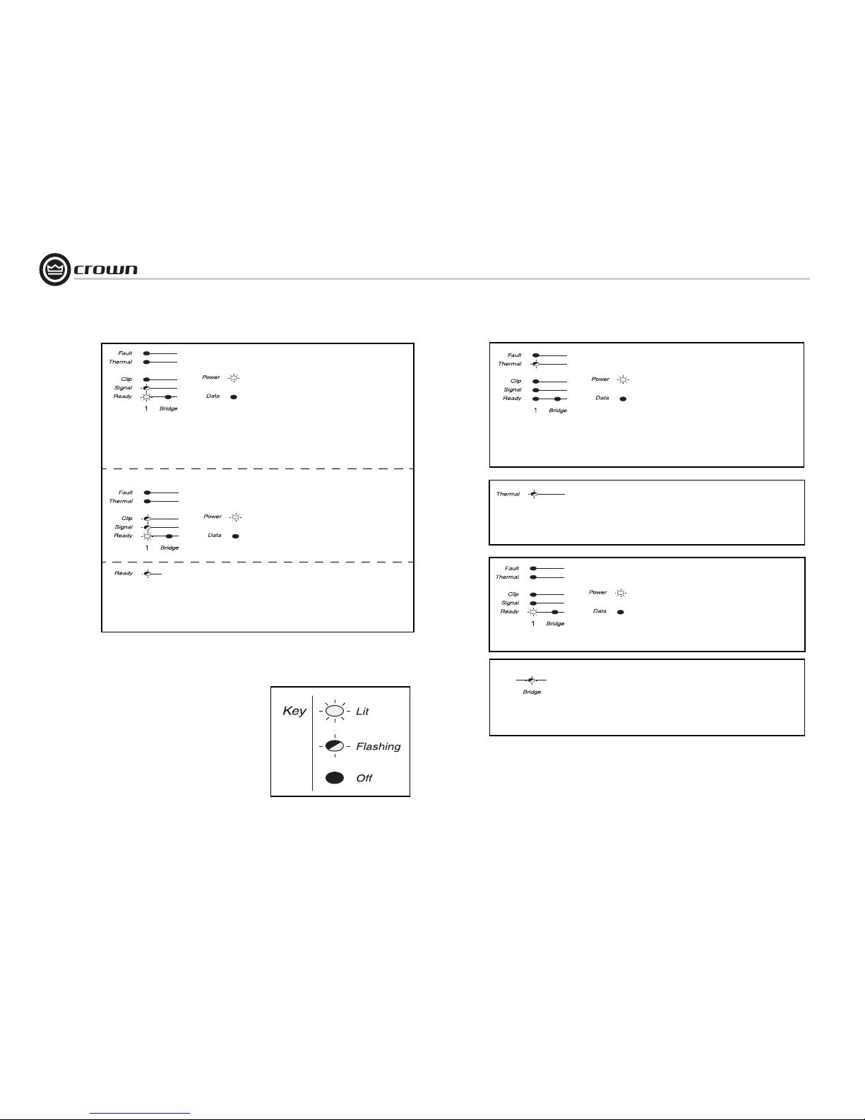
Operation Manual
CTs Power Amplifiers
page 46
CONDITION: No sound, even though
the amp has power. Power LED is on
without flashing and the amp is receiving an
input signal. Signal indicator is flashing.
• Speakers not connected.
• Open circuit due to speaker failure.
CONDITION: No input signal.
(Signal indicator is not flashing even though
audio is applied and channel is ready).
POSSIBLE REASON:
• Input signal level is very low.
• Input cables have become disconnected.
• There is a short on the amplifier
output. First disconnect your speakers
from the affected channel(s) one by one
to determine if one of the loads is
shorted.
6 Troubleshooting
CONDITION: Thermal indicator is
flashing.
POSSIBLE REASON:
• The amplifier has become too hot for
safe operation. Check for loads less than
2 ohms, and for excessive input levels.
Check for proper ventilation and proper
mode-switch setting. Driving lowimpedance loads while in high-voltage
mode can cause overheating.
CONDITION: All channel thermal
indicators are flashing.
POSSIBLE REASON:
• Power supply thermal overload.
• DC or excessive low-frequency signal at
the amplifier’s output has enabled
speaker protection.
CONDITION: Bridge LED is flashing.
POSSIBLE REASON:
• The mode switch was switched while the
power was on.
Page 47
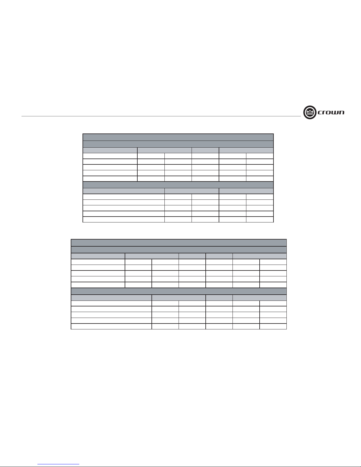
page 47
CTs Power Amplifiers
Operation Manual
7 Specifications
Channel Pairs Driven
160
200
200
175
155
185*
250
190
220
260
200
240
270
220
250
230
220
230*
400
320
200
350
310
185*
540
440
250
460
440
230*
500
380
220
Bridge-Mono Mode
8 Ohm
16 Ohm
100V (50 Ohm) at 0.1% THD
70V (25 Ohm) at 0.1% THD
8 Ohm
4 Ohm
Channels Driven
Dual Mode
1 kHz 1 kHz 1 kHz
1 kHz
20 Hz - 20 kHz
1 kHz
20 Hz - 20 kHz
20 Hz - 20 kHz
1 kHz
1 kHz 20 Hz - 20 kHz
CTs 8200: MINIMUM GUARANTEED POWER
(In watts, 0.1% THD) 120VAC, 60 Hz units
8
4
2
1
42
1
* Constant Voltage full bandwidth power ratings support 100 Hz - 20 kHz due to automatic high-pass filters.
Channels Driven
2
4
1
21
1 kHz 20 Hz - 20 kHz 1 kHz 1 kHz 20 Hz - 20 kHz
4 Ohm 260 215 270 270 225
8 Ohm 180 190 210 220 210
70V
(
25 Ohm) at 0.1% THD
220 220* 240 250 245*
Channel Pairs Driven
1 kHz 20 Hz - 20 kHz 1 kHz 20 Hz - 20 kHz
520 430 560 450
400 380 440 420
220 220* 250 245*
8 Ohm
16 Ohm
100V (50 Ohm)
Bridge-Mono Mode
CTs 4200: MINIMUM GUARANTEED POWER
(in watts, 0.1% THD) 120VAC, 60 Hz units
Dual Mode
at 0.1% THD
* Constant Voltage full bandwidth power ratings support 100 Hz - 20 kHz due to automatic high-pass filters.
Figure 7.1 CTs 4200
Power Chart
Figure 7.2 CTs 8200
Power Chart
Page 48
Operation Manual
CTs Power Amplifiers
page 48
7 Specifications
Performance CTs 4200 CTs 8200
Frequency Response (at 1 watt, 20 Hz - 20 kHz) ± 0.5 dB ± 0.5 dB
Phase Response (at 1 watt, 10 Hz - 20 kHz) ± 35° ± 35°
Signal to Noise Ratio below rated power (20 Hz to 20 kHz) 100 dB unweighted 100 dB unweighted
Total Harmonic Distortion (THD) at 1 watt, from 20 Hz to 20 kHz < 0.05% < 0.05%
Intermodulation Distortion (IMD) 60 Hz and 7 kHz at 4:1,
from 163 milliwatts to full bandwidth power, typical
< 0.05% < 0.05%
Damping Factor: 10 Hz to 400 Hz >180 >180
Crosstalk (below rated power, 20 Hz to 1 kHz) > 80 dB > 80 dB
Common Mode Rejection (CMR) (20 Hz to 1 kHz) > 50 dB > 50 dB
DC Output Offset (Shorted input) < ± 5 mV < ± 5 mV
Input Impedance nominally balanced, nominally unbalanced 20 kilohms, 10 kilohms 20 kilohms, 10 kilohms
Maximum Input Level (before input compression) + 20 dBu + 20 dBu
Load Impedance (Note: Safe with all types of loads)
Stereo
Bridge Mono
4/8 and 25 ohms (70V)
8/16 and 50 ohms (100V)
4/8 and 25 ohms (70V)
8/16 and 50 ohms(100V)
Voltage Gain (at maximum level setting), 1.4V sensitivity
4/8 Ohm Operation
70V Operation
100V Operation
20:1 (26 dB)
50:1 (34 dB)
71.4:1 (37 dB)
20:1 (26 dB)
50:1 (34 dB)
71.4:1 (37 dB)
Required AC Mains (model dependent) 120V, 60 Hz. 220/230/240V, 50 Hz 100V, 50/60Hz. 120V, 60 Hz. 220/230/240V, 50 Hz
Power Draw at Idle (120VAC mains, all channels in 4/8 ohm mode) 70W 70W
Power Draw at Idle (120VAC mains, all channels in 70V mode) 114W 114W
Cooling Continuously variable speed forced air, front-to-back airflow Continuously variable speed forced air, front-to-back airflow
Dimensions: Width, Height, Depth 19 in. (48.3 cm) W x 3.5 in. (8.9 cm) H x 16.25 in. (41.3 cm) D 19 in. (48.3 cm) W x 5.25 in. (13.3 cm) H x 16.25 in. (41.3 cm) D
Net Weight, Shipping Weight 2 6 l b . 6 o z . (1 2 k g ) , 3 0 l b. 1 4 o z. ( 1 4 k g ) 36 l b. 6 o z . ( 16 . 5 k g ) , 4 7 l b . (2 1 . 3 k g )
The following specifications apply to all models in Dual 8/4 ohm mode with 8-ohm loads unless otherwise specified.
Page 49
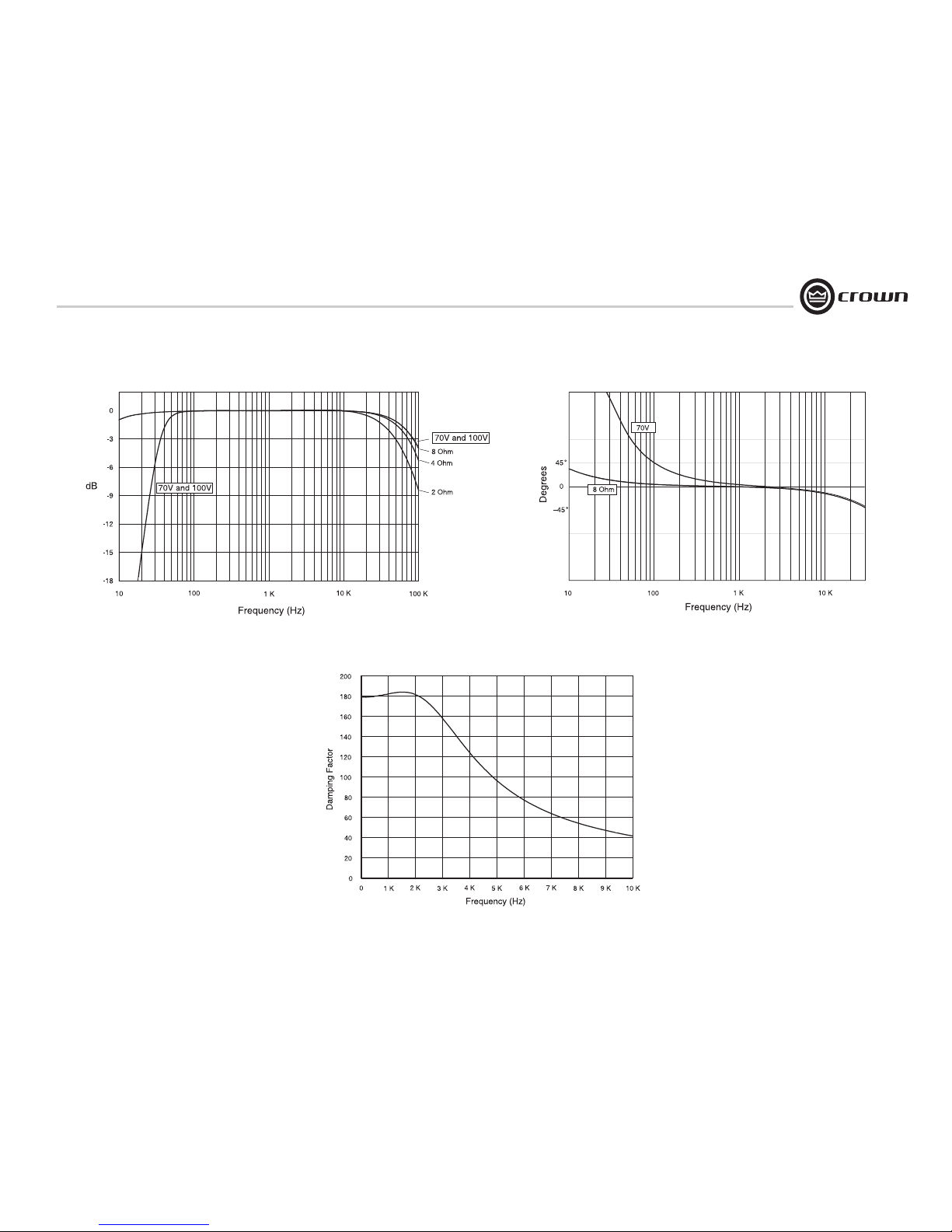
page 49
CTs Power Amplifiers
Operation Manual
7 Specifications
Figure 7.3 CTs 8200 Typical Frequency Response (1 W)
Figure 7.4 CTs 8200 Typical Phase Response (1 W)
Figure 7.5 CTs 8200 Typical Damping Factor vs. Frequency
Page 50
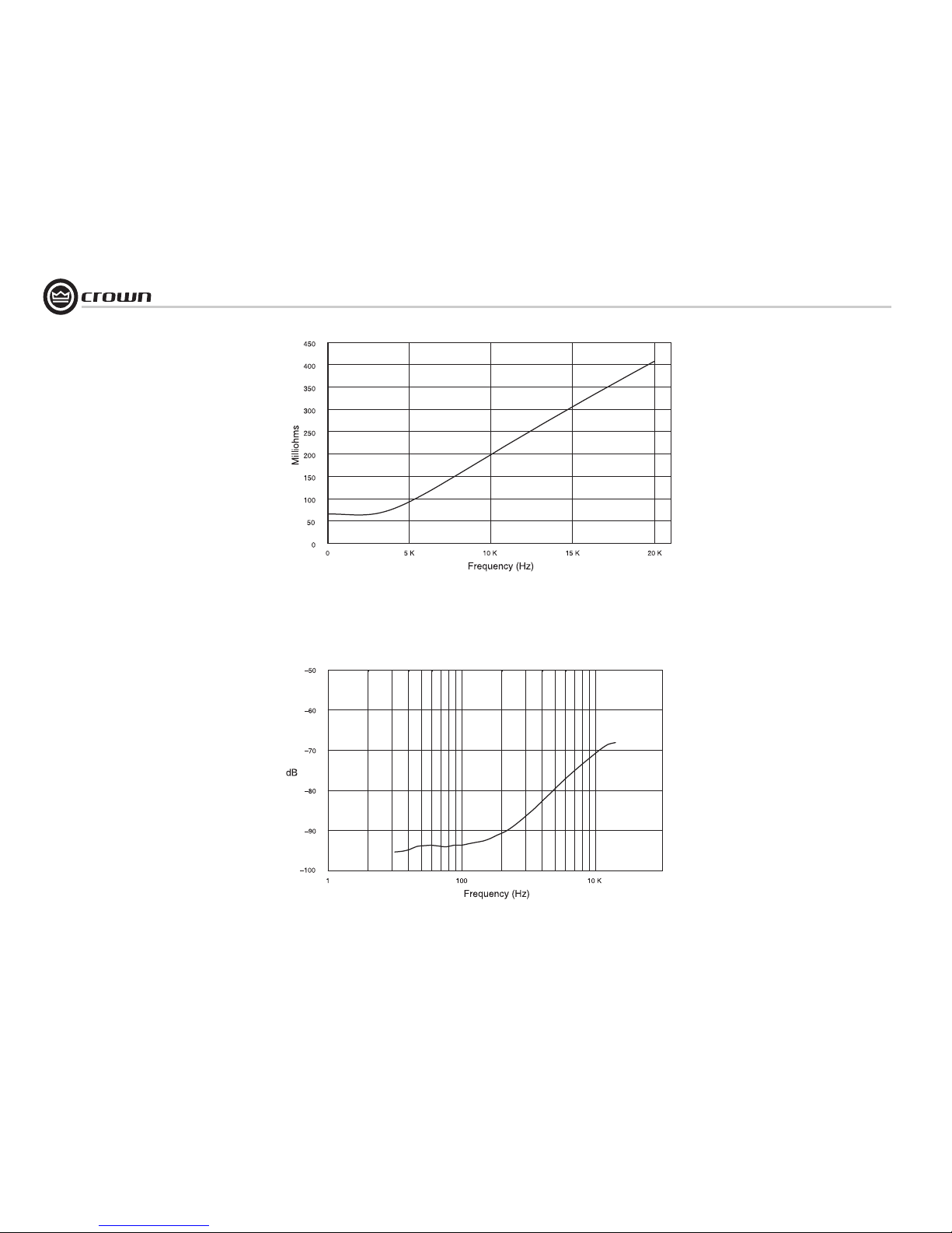
Operation Manual
CTs Power Amplifiers
page 50
Figure 7.6 CTs 8200 Typical Output Impedance vs. Frequency
Figure 7.7 CTs 8200 Typical Crosstalk vs. Frequency
7 Specifications
Page 51
page 51
CTs Power Amplifiers
Operation Manual
AC Power Draw and Thermal Dissipation:
Pink noise 12dB crest factor, bandwidth limited 22Hz to 22kHz.
Typical line impedance used.
Measurements made with 120VAC mains. Line current figures for 230VAC units derived by multiplying 120VAC figures by 0.5.
Data based on all channels driven.
watts in
watts out dissapated
Btu/hr kcal/hr
At Idle (8.4 Ohm mode )
70 0 70 239 60
At Idle (70/100V mode)
114 0 114 389 98
1/8th Power Pink Noise 8 Ohms/Ch.
200x4
Typical of program material 16 Ohms Bridge
400x2
just at clip. 4 Ohms/Ch.
260x4
8 Ohms Bridge
520x2
70V/Ch. 220x4
100V Bridge 220x2
1/3rd Power Pink Noise 8 Ohms/Ch.
200x4
Typical of program material 16 Ohms Bridge
400x2
with severe clipping. 4 Ohms/Ch.
260x4
8 Ohms Bridge
520x2
70V/Ch. 220x4
100V Bridge 220x2
382 1303 3297.9 4.0 668 286
391 1336 337
11.8 5.9 1005 349 655 2236 564
7.6 3.8 648 257
318 1084 2735.3 2.7 427 110
301 1027 259
7.8 3.9 639 134 505 1722 434
5.2 2.6 400 99
CTs 4200
Load
Rated
Power
Line Current
120VAC
Line Current
230VAC
Watts
Thermal Dissipation
8 AC Power Draw and
Thermal Dissipation
Page 52
Operation Manual
CTs Power Amplifiers
page 52
AC Power Draw and Thermal Dissipation:
Pink noise 12dB crest factor, bandwidth limited 22Hz to 22kHz.
Typical line impedance used.
Measurements made with 120VAC mains. Line current figures for 230VAC units derived by multiplying 120VAC figures by 0.5.
Data based on all channels driven.
watts in
watts out dissapated
Btu/hr kcal/hr
At Idle (8.4 Ohm mode )
70 0 70 239 60
At Idle (70/100V mode)
114 0 114 389 98
1/8th Power Pink Noise 8 Ohms/Ch.
160x8
Typical of program material 16 Ohms Bridge
320x4
just at clip. 4 Ohms/Ch.
200x8
8 Ohms Bridge
400x4
70V/Ch. 200x8
100V Bridge 200x4
1/3rd Power Pink Noise 8 Ohms/Ch.
160x8
Typical of program material 16 Ohms Bridge
320x4
with severe clipping. 4 Ohms/Ch.
200x8
8 Ohms Bridge
400x4
70V/Ch. 200x8
100V Bridge 200x4
CTs 8200
Load
Rated
Power
Line Current
120VAC
Line Current
230VAC
Watts
Thermal Dissipation
8.7 4.3 725 172 553 1889 476
13.3 6.7 1155 218 938 3200 807
10.1 5.1 857 203 653 2230 562
13.1 6.5 1136 437 699 2385 601
19.3 9.7 1748 557 1190 4062 1024
15.3 7.7 1344 552 792 2702 681
8 AC Power Draw and
Thermal Dissipation
Page 53

page 53
CTs Power Amplifiers
Operation Manual
9 Service
Crown amplifiers are quality units that rarely require servicing. Before returning your unit for service, please contact Crown Technical Support to verify the need for
servicing.
This unit has very sophisticated circuitry which should
only be serviced by a fully trained technician. This is one
reason why each unit bears the following label:
CAUTION: To prevent electric shock, do not
remove covers. No user serviceable parts
inside. Refer servicing to a qualified technician.
Complete the Crown Audio Factory Service Information
form, in the back of this manual, when returning a Crown
product to the factory or authorized service center. The
form must be included with your product inside the box
or in a packing slip envelope securely attached to the
outside of the shipping carton. Do not send this form
separately.
Warranty is only valid within the country in which the
product is purchased.
9.1 International and Canada Service
Service may be obtained from an authorized service center. (Contact your local Crown/Amcron representative or
our office for a list of authorized service centers.) To
obtain service, simply present the bill of sale as proof of
purchase along with the defective unit to an authorized
service center. They will handle the necessary paperwork
and repair.
Remember to transport your unit in the original factory
pack.
9.2 US Service
Service may be obtained in one of two ways: from an
authorized service center or from the factory. You may
choose either. It is important that you have your copy of
the bill of sale as your proof of purchase.
9.2.1 Service at a US Service Center
This method usually saves the most time and effort. Simply present your bill of sale along with the defective unit
to an authorized service center to obtain service. They
will handle the necessary paperwork and repair. Remember to transport the unit in the original factory pack. A list
of authorized service centers in your area can be obtained
from Crown Factory Service, or online from
http://www.crownaudio.com/support/servcent.htm.
9.2.2 Factory Service
Crown accepts no responsibility for non-serviceable
product that is sent to us for factory repair. It is the
owner’s responsibility to ensure that their product is serviceable prior to sending it to the factory. Serviceable
product list is available at
http://crownweb.crownintl.com/crownrma/.
For more information, please contact us direct.
A Service Return Authorization (SRA) is required for
product being sent to the factory for repair. An SRA can
be completed online at www.crownaudio.com/support/
factserv.htm. If you do not have access to the web, please
call Crown’s Customer Service at 574.294.8200 or
800.342.6939 extension 8205.
For warranty service, we will pay for ground shipping
both ways in the United States. Contact Crown Customer
Service to obtain prepaid shipping labels prior to sending the unit. Or, if you prefer, you may prepay the cost of
shipping, and Crown will reimburse you. Send copies of
the shipping receipts to Crown to receive reimbursement.
Your repaired unit will be returned via UPS ground.
Please contact us if other arrangements are required.
9.2.3 Factory Service Shipping Instructions:
1. Ser vice Return Authorization (SRA) is required for
product being sent to the factory for service. Please
complete the SRA by going to
www.crownaudio.com/support/factserv.htm. If you
do not have access to our website, call
1.800.342.6939, extension 8205 and we'll create the
SRA for you.
2. See packing instructions that follow.
3. Ship product to:
CROWN AUDIO FACTORY SERVICE
1718 W MISHAWKA RD.
ELKHART, IN 46517
4. Use a bold black marker and write the SRA number
on three sides of the box.
5. Record the SRA number for future reference. The
SRA number can be used to check the repair status.
9.2.4 Packing Instructions
Important: These instructions must be followed. If they
are not followed, Crown Audio, Inc. assumes no responsibility for damaged goods and/or accessories that are
sent with your unit.
1. Fill out and include the Crown Audio Factory Service Information sheet in the back of this manual.
2. Do not ship any accessories (manuals, cords, hardware, etc.) with your unit. These items are not
needed to service your product. We will not be
responsibility for these items.
3. When shipping your Crown product, it is important
that it has adequate protection. We recommend you
use the original pack material when returning the
product for repair. If you do not have the original
box, please call Crown at 800.342.6939 or
574.294.8210 and order new pack material. See
instructions for “foam-in-place” shipping pack. (Do
not ship your unit in a wood or metal cabinet.)
4. If you provide your own shipping pack, the minimum recommended requirements for materials are
as follows:
a. 275 P.S.I. burst test, Double-Wall carton that allows
for 2-inch solid Styrofoam on all six sides of unit or
3 inches of plastic bubble wrap on all six sides of
unit.
b. Securely seal the package with an adequate carton
sealing tape.
c. Do not use light boxes or “peanuts”. Damage caused
by poor packaging will not be covered under warranty.
Using your 'foam-in-place' shipping pack
Note: The foam-in-place packing is molded so that there
is only one correct position for your product.
1. Open carton and lift center cushion leaving both
end-cushions in place.
2. Carefully place your product with the product's front
panel facing the same direction as arrows indicate.
3. Reset center cushion down over top of product's
chassis. The foam-in-place packing was molded to
accommodate different chassis depth sizes. If your
product's chassis does not completely fill the foamin-place cavity, you may use a soft but solid packing
material (such as paper or bubble wrap) behind the
chassis.
4. Enclose the completed Crown Audio Factor y Service
Information form (or securely attach it to the outside
of carton) and re-seal the shipping pack with a
sturdy carton sealing tape.
9.2.5 Estimate Approval
Approval of estimate must be given within 30 days after
being notified by Crown Audio Inc. Units still in the possession of Crown after 30 days of the estimate will
become the property of Crown Audio Inc.
9.2.6 Payment of Non-Warranty Repairs
Payment on out-of-waranty repairs must be received
within 30 days of the repair date. Units unclaimed after
30 days become the property of Crown Audio Inc.
If you have any questions, please contact Crown Factory
Service.
Crown Factory Service
1718 W. Mishawaka Rd.,
Elkhart, Indiana 46517 U.S.A.
Telephone:
574.294.8200
800.342.6939 (North America,
Puerto Rico, and Virgin Islands only)
Facsimile:
574.294.8301 (Technical Support)
574.294.8124 (Factory Service)
Internet:
http://www.crownaudio.com
Page 54
Operation Manual
CTs Power Amplifiers
page 54
10 Warranty
SUMMARY OF WARRANTY
Crown International, 1718 West Mishawaka Road,
Elkhart, Indiana 46517-4095 U.S.A. warrants to
you, the ORIGINAL PURCHASER and ANY SUBSEQUENT OWNER of each NEW Crown product,
for a period of three (3) years from the date of
purchase by the original purchaser (the “warranty
period”) that the new Crown product is free of
defects in materials and workmanship. We further
warrant the new Crown product regardless of the
reason for failure, except as excluded in this Warranty.
Warranty is only valid within the country in which
the product was purchased.
ITEMS EXCLUDED FROM THIS
CROWN WARRANTY
This Crown Warranty is in effect only for failure of
a new Crown product which occurred within the
Warranty Period. It does not cover any product
which has been damaged because of any intentional misuse, accident, negligence, or loss which
is covered under any of your insurance contracts.
This Crown Warranty also does not extend to the
new Crown product if the serial number has been
defaced, altered, or removed.
WHAT THE WARRANTOR WILL DO
We will remedy any defect, regardless of the reason for failure (except as excluded), by repair,
replacement, or refund. We may not elect refund
unless you agree, or unless we are unable to provide replacement, and repair is not practical or
cannot be timely made. If a refund is elected, then
you must make the defective or malfunctioning
product available to us free and clear of all liens
or other encumbrances. The refund will be equal
to the actual purchase price, not including interest, insurance, closing costs, and other finance
charges less a reasonable depreciation on the
product from the date of original purchase. Warranty work can only be performed at our authorized service centers or at the factory. Warranty
work for some products can only be performed at
our factory. We will remedy the defect and ship
the product from the service center or our factory
within a reasonable time after receipt of the defective product at our authorized service center or
our factory. All expenses in remedying the defect,
including surface shipping costs in the United
States, will be borne by us. (You must bear the
expense of shipping the product between any foreign country and the port of entry in the United
States including the return shipment, and all
taxes, duties, and other customs fees for such foreign shipments.)
HOW TO OBTAIN WARRANTY
SERVICE
You must notify us of your need for warranty service within the warranty period. All components
must be shipped in a factory pack, which, if
needed, may be obtained from us free of charge.
Corrective action will be taken within a reasonable time of the date of receipt of the defective
product by us or our authorized service center. If
the repairs made by us or our authorized service
center are not satisfactory, notify us or our authorized service center immediately.
DISCLAIMER OF CONSEQUENTIAL
AND INCIDENTAL DAMAGES
YOU ARE NOT ENTITLED TO RECOVER FROM
US ANY INCIDENTAL DAMAGES RESULTING
FROM ANY DEFECT IN THE NEW CROWN
PRODUCT. THIS INCLUDES ANY DAMAGE TO
ANOTHER PRODUCT OR PRODUCTS RESULTING FROM SUCH A DEFECT. SOME STATES DO
NOT ALLOW THE EXCLUSION OR LIMITATIONS
OF INCIDENTAL OR CONSEQUENTIAL DAMAGES, SO THE ABOVE LIMITATION OR EXCLUSION MAY NOT APPLY TO YOU.
WARRANTY ALTERATIONS
No person has the authority to enlarge, amend, or
modify this Crown Warranty. This Crown Warranty is not extended by the length of time which
you are deprived of the use of the new Crown
product. Repairs and replacement parts provided
under the terms of this Crown Warranty shall
carry only the unexpired portion of this Crown
Warranty.
DESIGN CHANGES
We reserve the right to change the design of any
product from time to time without notice and with
no obligation to make corresponding changes in
products previously manufactured.
LEGAL REMEDIES OF PURCHASER
THIS CROWN WARRANTY GIVES YOU SPECIFIC
LEGAL RIGHTS, YOU MAY ALSO HAVE OTHER
RIGHTS WHICH VARY FROM STATE TO STATE.
No action to enforce this Crown Warranty shall be
commenced after expiration of the warranty
period.
THIS STATEMENT OF WARRANTY SUPERSEDES
ANY OTHERS CONTAINED IN THIS MANUAL
FOR CROWN PRODUCTS. 9/07
UNITED STATES & CANADA
Page 55

page 55
CTs Power Amplifiers
Operation Manual
10 Warranty
WORLDWIDE EXCEPT USA & CANADA
SUMMARY OF WARRANTY
Crown International, 1718 West Mishawaka Road,
Elkhart, Indiana 46517-4095 U.S.A. warrants to
you, the ORIGINAL PURCHASER and AN Y SUBSEQUENT OWNER of each NEW Crown1 product,
for a period of three (3) years from the date of purchase by the original purchaser (the “warranty
period”) that the new Crown product is free of
defects in materials and workmanship, and we
further warrant the new Crown product regardless
of the reason for failure, except as excluded in this
Warranty.
Warranty is only valid within the country in which
the product is purchased.
1 Note: If your unit bears the name “Amcron,” please substitute
it for the name “Crown” in this warranty.
ITEMS EXCLUDED FROM THIS CROWNWARRANTY
This Crown Warranty is in effect only for failure of
a new Crown product which occurred within the
Warranty Period. It does not cover any product
which has been damaged because of any intentional misuse, accident, negligence, or loss which
is covered under any of your insurance contracts.
This Crown Warranty also does not extend to the
new Crown product if the serial number has been
defaced, altered, or removed.
WHAT THE WARRANTOR WILL DO
We will remedy any defect, regardless of the reason for failure (except as excluded), by repair,
replacement, or refund. We may not elect refund
unless you agree, or unless we are unable to provide replacement, and repair is not practical or
cannot be timely made. If a refund is elected, then
you must make the defective or malfunctioning
product available to us free and clear of all liens
or other encumbrances. The refund will be equal
to the actual purchase price, not including interest, insurance, closing costs, and other finance
charges less a reasonable depreciation on the
product from the date of original purchase. Warranty work can only be performed at our authorized service centers. We will remedy the defect
and ship the product from the service center
within a reasonable time after receipt of the defective product at our authorized service center.
HOW TO OBTAIN WARRANTY SERVICE
You must notify your local Crown importer of
your need for warranty service within the warranty
period. All components must be shipped in the
original box. Corrective action will be taken within
a reasonable time of the date of receipt of the
defective product by our authorized service center.
If the repairs made by our authorized service center are not satisfactory, notify our authorized service center immediately.
DISCLAIMER OF CONSEQUENTIAL AND
INCIDENTAL DAMAGES
YOU ARE NOT ENTITLED TO RECOVER FROM US
ANY INCIDENTAL DAMAGES RESULTING FROM
ANY DEFECT IN THE NEW CROWN PRODUCT.
THIS INCLUDES ANY DAMAGE TO ANOTHER
PRODUCT OR PRODUCTS RESULTING FROM
SUCH A DEFECT.
WARRANTY ALTERATIONS
No person has the authority to enlarge, amend, or
modify this Crown Warranty. This Crown Warranty
is not extended by the length of time which you are
deprived of the use of the new Crown product.
Repairs and replacement parts provided under the
terms of this Crown Warranty shall carry only the
unexpired portion of this Crown Warranty.
DESIGN CHANGES
We reserve the right to change the design of any
product from time to time without notice and with
no obligation to make corresponding changes in
products previously manufactured.
LEGAL REMEDIES OF PURCHASER
No action to enforce this Crown Warranty shall be
commenced after expiration of the warranty
period.
THIS STATEMENT OF WARRANTY SUPERSEDES
ANY OTHERS CONTAINED IN THIS MANUAL FOR
CROWN PRODUCTS. 9/07
Page 56

Operation Manual
CTs Power Amplifiers
page 56
NOTES
Page 57
page 57
CTs Power Amplifiers
Operation Manual
Online registration is also available at http://crownweb.crownintl.com/webregistration
When this form is used to register your product, it may be mailed or faxed.
Crown Audio, Inc. Fax: 574-294-8329
1718 W Mishawaka Rd
Elkhart IN 46517
Please note that some information is required. Incomplete registrations will not be processed. * Indicates required information.
OWNER'S INFORMATION - PLEASE PRINT
* First name: ______________________ Middle initial: _____ * Last name: ________________________________
Company: _________________________________________________________________________________
* Mailing address: ____________________________________________________________________________
* City: ____________________________* State: ___________________________* Zip Code: ________________
* Country: __________________________ E-mail address: ___________________________________________
* Phone # (include area code): ___________________________ Fax #: __________________________________
* MODEL * SERIAL # PURCHASE DATE
ie. IT8000, CDi1000, PCC160 i.e. 8000000000 mo/day/yr
________________________________ ____________________ ______ /_____ /_____
________________________________ ____________________ ______ /_____ /_____
________________________________ ____________________ ______ /_____ /_____
________________________________ ____________________ ______ /_____ /_____
Product purchased from: ___________________________ City: __________________ State: ___________
Comments: ____________________________________________________________________________________
_____________________________________________________________________________________________
_____________________________________________________________________________________________
Crown Audio, Inc.
1718 W. Mishawaka Rd.
Elkhart, IN 46517-9439
Phone: 574-294-8000
Fax: 574-294-8329
www.crownaudio.com
PRODUCT REGISTRATION
PRODUCT INFORMATION
CUT ON THIS LINE
Page 58

Operation Manual
CTs Power Amplifiers
page 58
THIS PAGE INTENTIONALLY LEFT BLANK
Page 59
page 59
CTs Power Amplifiers
Operation Manual
Crown Factory Service Information
Shipping Address: Crown Factory Service, 1718 W. Mishawaka Rd., Elkhart, IN 46517
PLEASE PRINT CLEARLY
SRA #: __________________(If sending product to Crown factory service.) Model: _________________________________ Serial Number: _____________________ Purchase Date: ________________
PRODUCT RETURN INFORMATION
Individual or Business Name:
___________________________________________________________________________________________________________________________________________________________________________
Phone #: __________________________________________________ Fax #: ________________________________________ Email: ____________________________________________________
Street Address (please, no P.O. Boxes):
___________________________________________________________________________________________________________________________________________________________________________
City: __________________________________________ State/Prov: ________________________________ Postal Code: _________________ Countr y: _____________________
Nature of problem:
___________________________________________________________________________________________________________________________________________________________________________
___________________________________________________________________________________________________________________________________________________________________________
___________________________________________________________________________________________________________________________________________________________________________
Other equipment in your system:
___________________________________________________________________________________________________________________________________________________________________________
If warranty is expired, please provide method of payment. Proof of purchase may be required to validate warranty.
PAYMENT OPTIONS
I have open account payment terms. Purchase order required. PO#____________________________________________________ COD
Credit Card (Information below is required; however if you do not want to provide this information at this time, we will contact you for the information when your unit is repaired).
Credit card information:
Type of credit card: Master Card Visa American Express Discover
Type of credit card account: Personal/Consumer Business/Corporate
Card # ______________________________________________ Exp. date: _____________ * Card ID #: __________________________
* Card ID # is located on the back of the card following the credit card #, in the signature area. On American Express, it may be located on the front of the card. This number is required to process the charge to your account. If you do not want
to provide it at this time, we will call you to obtain this number when the repair of your unit is complete.
Name on credit card: ____________________________________________________________________________
Billing address of credit card: __________________________________________________________________________
__________________________________________________________________________
__________________________________________________________________________
Page 60

 Loading...