

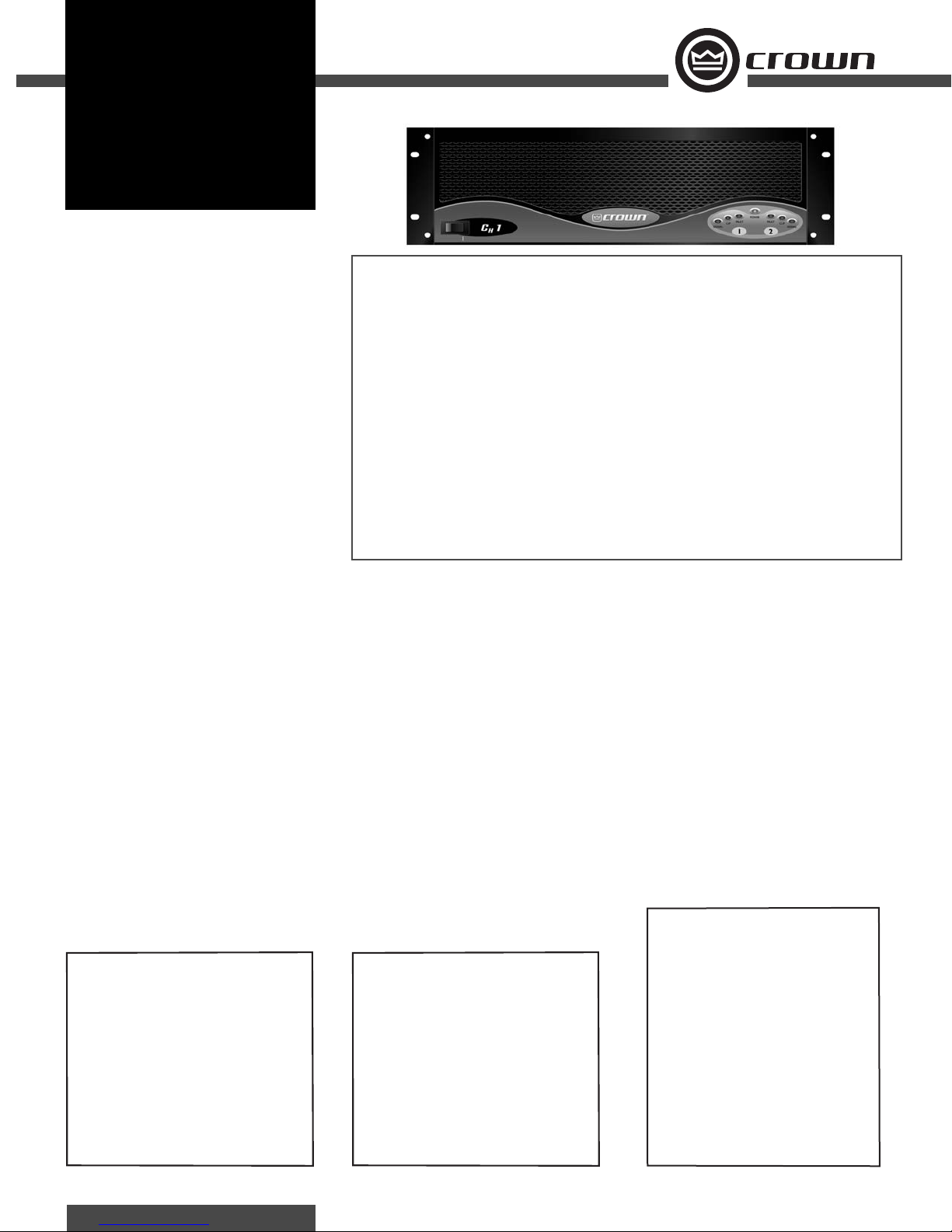
Crown CH1, CH2, CH3, CH4 Specifications
CH1
CH2
CH4
ooking for a quality, constant voltage and low
impedance two channel amplifi er for your restaurant, nightclub, retail store, school or house
L
of worship projects? The Crown
amplifi ers are designed just for you.
CH-Series amplifi ers can directly drive “constant
voltage” lines, so you can avoid the expense of
adding step-up transformers for distributed loudspeaker systems.
All Contractor-Series amplifi ers feature Crown’s
exclusive SST (System Solutions Topologies) expansion system. The SST expansion system makes it
easy to tailor your amplifi er to a specifi c application
or to add future technology as it develops.
With an incredibly wide range of power and feature/benefi ts, Contractor-Series amplifi ers give the
professional sound contractor more options. Crown
quality is available at the best dollar-per-watt ratio on
the market.
For more details about the Crown Contractor Series,
contact the Crown Technical Support Group at 800342-6939 or 574-294-8200. Also, visit the Crown
Audio website at www.crownaudio.com.
®
“Contractor Series”
CONTRACTOR SERIES
Features
• Drives multiple impedances, with both low
impedance and high impedance outputs per
channel.
• High-pass filter for each channel provides
low-frequency roll off to eliminate step down
transformer saturation when used in 70V distributed systems.
• Shallow chassis design, allowing for installation in most wall-mount racks.
• Rear panel detented level controls allow for
accurate level settings and secure operation.
• “Contractor-Correct” barrier strip output connectors allow for quick and easy connection,
regardless of the load.
• Advanced protection circuitry guards against:
shorted outputs, open circuits, DC, mismatched
loads, general overheating, high-frequency
overloads and internal faults.
• Can be mounted in standard (19-inch (48.3cm)) rack, shallow (14-inch (35.56-cm)) rack,
or stacked on top of each other.
• Accurate, uncolored sound with very low
distortion for the best in music and voice reproduction.
• Three-Year, No-Fault, Fully Transferable Warranty completely protects your investment and
guarantees its specifi cations.
• Crown’s Profi t Protection Plan guarantees quick,
no-questions-asked replacement of your covered
Contractor Series amplifi er should it fail at any
time up to 6 months following date of installation.
Specifi cations
Note: All measurements apply to amplifi ers in stereo
mode with 8 ohm loads and an input sensitivity of 26
dB gain, 1 kHz at rated power unless other otherwise
specifi ed. Specifi cations for units supplied outside
the U.S.A. may vary slightly at different AC voltages
and frequencies.
Power
Output Power: See power charts below.
Load Impedance:
Safe with all types of loads.
4 and 8 ohm Stereo.
16 ohm (CH1) or 8 ohm (CH2) or 4 ohm (CH4) at
70V Stereo.
4, 8 and 16 ohm Bridge.
32 ohm (CH1) or 16 ohm (CH2) or 8 ohm (CH4) at
140V Bridge.
64 ohm (CH1) or 32 ohm (CH2) at 200V Bridge.
*
CH1
4 ohm Stereo (per channel)
8 ohm Stereo (per channel)
70V Stereo (per channel)
8 ohm Bridge-Mono
140V Bridge-Mono
*1 kHz Power: refers to maximum average power in watts
at 1 kHz with 0.5% THD.
1 kHz
Power
450W
275W
300W
900W
600W
Voltage Gain, 1 kHz, 1.4V sensitivity:
30.5 dB (CH1) or 32.1 dB (CH2) or 34 dB (CH4)
at 8 ohms.
34 dB (CH1) or 34 dB (CH2) or 34 dB (CH4) at
70V.
AC Line Requirements:
Note: North American units are 60 Hz only. All other
models are 50/60 Hz. Voltages are ±10%.
AC Line Current:
100V: 7.6A (CH1) or 11.4A (CH2) or 8.5A (CH4).
120V: 6.3A (CH1) or 9.5A (CH2) or 7.1A (CH4).
230-240V: 3.5A (CH1) or 5.0A (CH2) or
3.7A (CH4).
AC Line Connector: Detachable 15A IEC connector
with country-specifi c plug.
*
1 kHz
CH2
4 ohm Stereo (per channel)
8 ohm Stereo (per channel)
70V Stereo (per channel)
8 ohm Bridge-Mono
140V Bridge-Mono
*1 kHz Power: refers to maximum average power in watts
at 1 kHz with 0.5% THD.
Power
660W
400W
600W
1,320W
1,200W
Performance
Frequency Response, 20 Hz to 20 kHz at 1 watt: ±0.1
dB (CH1, CH2) or ±0.25 dB (CH4).
Phase Response: ±15 degrees deviation from linear
phase from 20 Hz to 20 kHz at 1 watt.
Signal to Noise Ratio, A-Weighted: Better than 105
dB (CH1, CH2) or 102 dB (CH4) below rated 1-kHz
power.
Total Harmonic Distortion (THD), 1 kHz at rated
power: 0.5% or less true THD from 20 Hz to 20 kHz.
Intermodulation Distortion (60 Hz and 7 kHz at 4:1):
Less than 0.1% (CH1, CH2) or 0.5% (CH4) at rated
power to 30 dB below rated power at 8 ohms.
Damping Factor (8 ohm): Better than 400 (CH1, CH2)
or 700 (CH4) from 10 Hz to 400 Hz.
Crosstalk, 20 Hz to 20 kHz: Better than 50 dB below
rated power.
Common Mode Rejection (CMR): Better than 40 dB
from 20 Hz to 1 kHz.
DC Output Offset (shorted Input): < ±10 mV.
*
CH4
2 ohm Stereo (per channel)
4 ohm Stereo (per channel)
8 ohm Stereo (per channel)
70V Stereo (per channel)
4 ohm Bridge-Mono
8 ohm Bridge-Mono
140V Bridge-Mono
*1 kHz Power: refers to maximum average power in watts
at 1 kHz with 0.5% THD.
**≥200V line voltage provides 1800W (2 ohm stereo)
and 3600W (4 ohm bridge-mono).
1 kHz
Power
1,400W**
1,200W
600W
1,200W
2,800W**
2,400W
2,400W
CH1
CH2
CH4
Controls
Level: A detented rotary level control for each channel
located on the rear panel.
Power: An on/off rocker switch located on the front
panel.
Mode: A two-position switch located on the back
panel which, when turned to “Stereo,” operates
the amplifi er as two independent channels. When
“Bridge” is selected, the amplifi er bridges the two
output channels for twice the output voltage.
Channel Operation Switch: A two-position switch
located on the back panel which, when turned to
4/8 Ohm, sets the amplifi er to drive low-impedance speaker loads. Turning the switch to 70V sets
the amplifi er to drive distributed high-impedance
speaker loads and inserts a 70 Hz high-pass fi lter into
the signal chain to prevent step-down transformer
saturation.
Indicators
Signal: A green indicator for each channel which
fl ashes when a very low-level signal (> –40 dBm) is
present at input. May be used for troubleshooting
cable runs.
Clip: A red indicator for each channel which turns
on when distortion becomes audible in the amplifi er
output.
Fault: A red indicator for each channel which indicates amplifi er has muted output. Normally off. Status
may be monitored remotely by plugging into backpanel RJ-11 Fault jack.
Power: A blue indicator that turns on when the amplifi er has been turned on and has power.
Input/Output
Input Connector (standard module): One per chan-
nel, 3-pin female XLR connector, in parallel with a
barrier strip termination.
Input Stage: Input is electronically balanced and
employs precision 1% resistors.
Input Impedance (nominal): 20 k ohms, balanced.
10 k ohms, unbalanced.
Input Sensitivity: Channel independent. Factory set at
1.4 volts for standard 1 kHz, 8 ohm power. 26 dB
gain and 0.775 volt sensitivity available as a Service
Option.
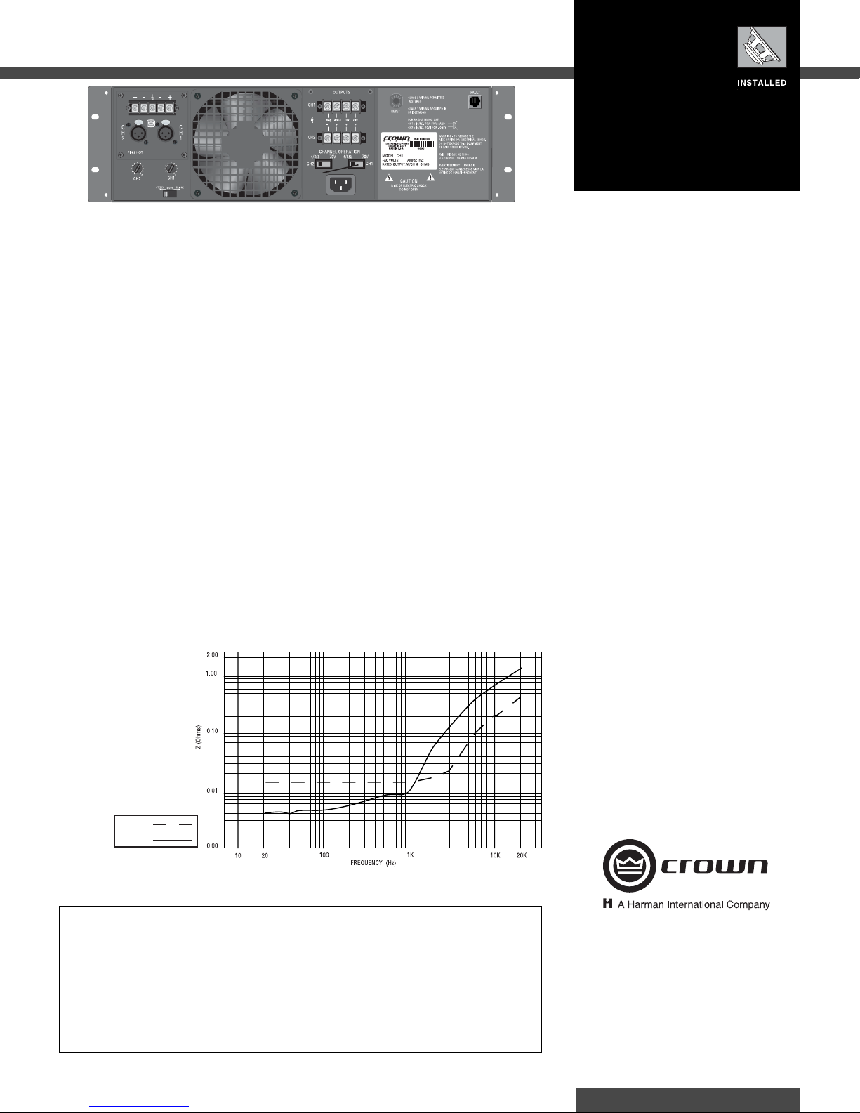
Output Impedance: See Figure 1.
Output Connectors: Four-terminal touch-proof barrier
block, one per channel.
Output Signal:
Stereo: Unbalanced, two-channel.
Bridge-Mono: Balanced, single-channel. Channel 1
controls are active; Channel 2 should be turned
down.
Protection
Contractor Series amplifi ers are protected against
shorted, open or mismatched loads; overloaded
power supplies; excessive temperature, chain
destruction phenomena, input overload damage and
high-frequency blowups. They also protect loudspeakers from input/output DC, large or dangerous DC offsets and turn-on/turn-off transients.
Options
Service Options: SST-4622, SST-3632, SST-4632—
custom two-channel crossover networks with equalization and delay purposely engineered for use with
JBL model 4622, 3632 and 4632 cinema speakers.
SST-SBSC 3632T, SST-SBSC 4632T—custom threechannel crossover networks with CD-horn equalization and mono-summed low-frequency outputs
similarly designed for use with JBL model 3632T and
4632T cinema speakers.
Construction
Rugged steel chassis is formed into a durable
package, then fi nished with environmentally friendly
powder coat for long life and ease of maintenance.
Cooling: Proportional speed fan in CH1 and CH2;
3-speed fan in CH4.
Dimensions:
Width: EIA Standard 19-inch rack mount (EIA RS-
310-B).
Height: 5.25 inches (13.34 cm).
Depth (behind front mounting surface):
CH1 and CH2: 12.25 inches (31.11 cm) to back of
amplifi er.
CH4: 16.25 inches (36.56 cm) to back of amplifi er.
CH4: 17.5 inches (14.45 cm) from back of front
rack ears to back of speaker-terminal cover.
Net Weight:
CH1: 40.6 lb (18.4 kg).
CH2: 48.3 lb (18.5 kg).
CH4: 33.4 lb (15.1 kg).
For shipping weight, add 6 lb (2.7 kg).
CH1, CH2
CH4
Figure 1 CH1, CH2, and CH4 Output Impedance
Crown’s Three-Year, No-Fault, Fully Transferable Warranty
Crown offers a Three-Year, No-Fault, Fully Transferable Warranty for every new Crown amplifi er—an unsurpassed industry standard. With this unprecedented No-Fault protection, your new Crown amplifi er is warranted
to meet or exceed original specifi cations for the fi rst three years of ownership. During this time, if your amplifi er
fails, or does not perform to original specifi cations, it will be repaired or replaced at our expense. About the
only things not covered by this warranty are those losses normally covered by insurance and those caused by
intentional abuse. And the coverage is transferable, should you sell your amplifi er.
See your authorized Crown dealer for full warranty disclosure and details. For customers outside of the USA,
please contact your authorized Crown distributor for warranty information or call 574-294-8200.
Crown Audio, Inc.
1718 W. Mishawaka Rd.
Elkhart, IN 46517-9439
TEL: 574-294-8200
FAX: 574-294-8FAX
www.crownaudio.com
Specifi cations subject to change without prior notice. Latest
information available at www.crownaudio.com.
Crown and Crown Audio are registered trademarks of Crown
International. Other trademarks are the property of their
respective owners. Printed in U.S.A.
©2005 Crown Audio
®
, Inc.
9/05 136706-1F
 Loading...