

Page 1
2 1
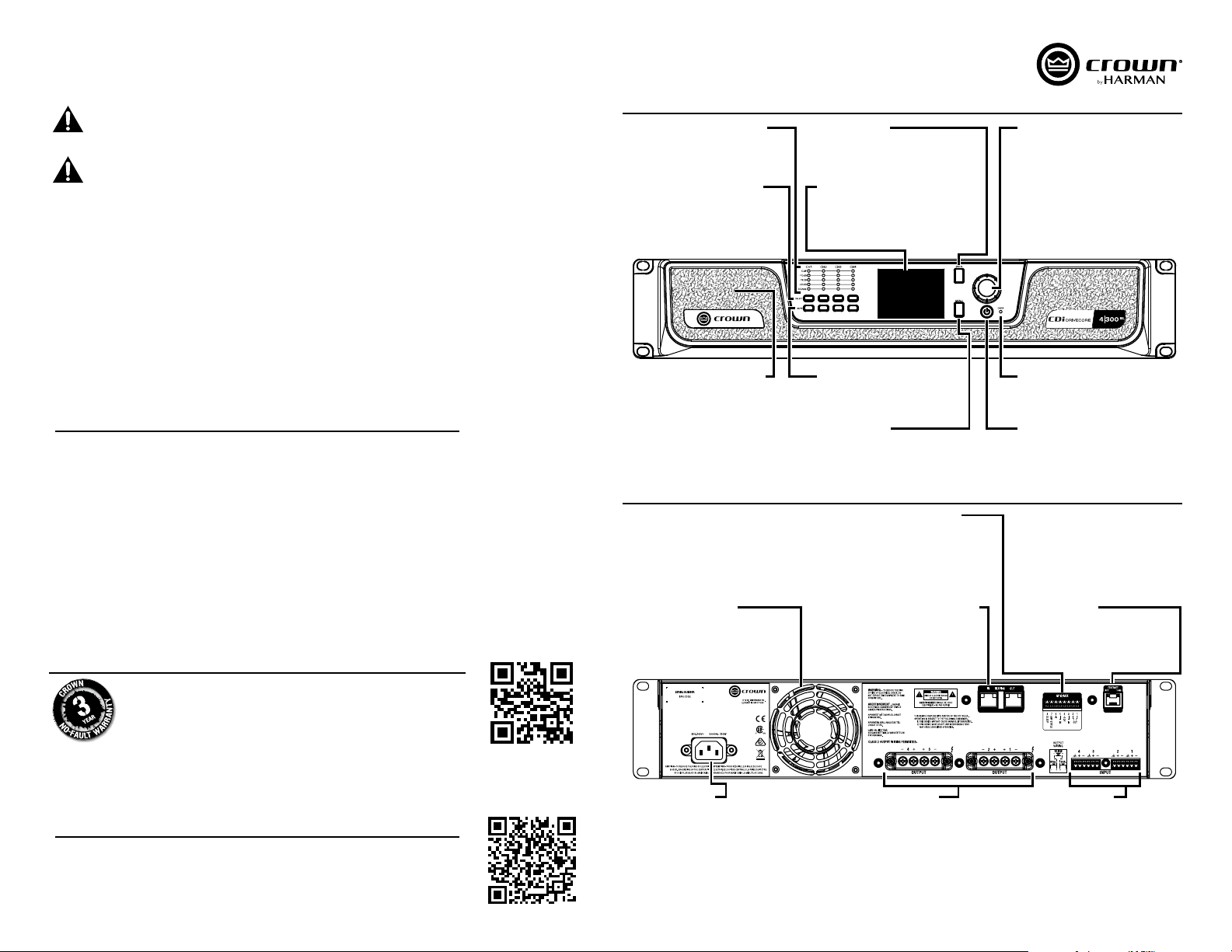
Cooling Fan Outlet
Provides cooling air flow. Do not block
or cover this outlet.
BLU Link Input/Output Ports
These two RJ45 ports are used for BLU
link audio transport and are available
only on BLU link-equipped CDi
DriveCore models.
General Purpose I/O Port
This port combines the 2-in, 2-out GPIO
with the SLEEP and AMP STATUS pin
from the AUX circuit. An 8-pin block
connector is provided for making
connections.
Ethernet Port
Connect this RJ45 port to a computer or
network for monitoring and controlling
the amp over Cat 5e wiring via the
Audio Architect software.
AC Power Inlet
Connect the included AC power cord to
this standard IEC type 320 C13 inlet.
Supported mains voltage range is
100-240V~.
Output Connectors
Connect these terminal output
connectors to your speakers. One
four-pole, touch-proof terminal strip is
provided per channel pair. Accepts up to
10 AWG wire or terminal forks.
Input Connectors
Connect your audio source(s) to these
inputs using the provided plug-in
connectors. One 6-pin plug-in
connector can be used per input pair.
These inputs are high impedance,
balanced connections.
CDi DriveCore Series Quick Start Guide
WARNING! READ THE IMPORTANT SAFETY INSTRUCTIONS PROVIDED IN THE BOX BEFORE OPERATING
THIS EQUIPMENT.
CAUTION: Before you begin, make sure your amplifier is disconnected from the power source and that all
channel levels are turned all the way down.
This quick start guide does not include all of the details of design, production, or variations of the equipment. Nor does it cover every
possible situation which may arise during installation, operation, or maintenance.
The information provided in this quick start guide was deemed accurate as of the publication date. However, updates to this information
may have occurred. Later versions of this quick start guide and additional information about this product may be available at the Crown
website at www.crownaudio.com.
Trademark Notice: Crown, Crown Audio, and Amcron are registered trademarks of Crown International. Other trademarks are the
property of their respective owners.
Some models may be exported under the name Amcron®
© 2016 by HARMAN International, Inc., 1718 W. Mishawaka Rd., Elkhart, Indiana 46517-9439 U.S.A. Telephone: 574-294-8000.
INCLUDED IN THE BOX
• CDi DriveCore Amplifier (1)
• 6-Pin Connectors (2 or 3 depending on amp model/channel count)
• 8-Pin GPIO Block Connector (1)
• Terminal Forks (5 or 10 depending on amp model/channel count)
• Clip On Ferrites (2, included with BLU link amp models only)
• Rear Rack Supports (2)
• Rack Mount Screw Kit (10 Screws and 10 Washers)
• Power Cable (1)
WARRANTY REGISTRATION
Register your product at http://warranty.harmanpro.com or scan the code to
the right with a QR scanner app on your mobile device to go straight to web URL.
Signal Level LED Meters
These meters indicate channel signal
levels.
Channel Select Buttons
Press to select a channel for editing.
Press and hold for channel information.
Cooling Vents/Air Filters
Provides cooling air flow. Do not block
or cover these vents.
Cooling Fan Outlet
Provides cooling air flow. Do not block
or cover this outlet.
FRONT PANEL
Back Button
Press to navigate back one level when
navigating menus.
Color LCD Display
Provides product information and visual
feedback for configuring and operating
the amp from the front panel.
Mute Buttons
Press to mute the corresponding
output channel.
Menu Button
Press to enter the System menu and edit
amp settings.
REAR PANEL
General Purpose I/O Port
This port combines the 2-in, 2-out GPIO
with the SLEEP and AMP STATUS pin
from the AUX circuit. An 8-pin block
connector is provided for making
connections.
BLU Link Input/Output Ports
These two RJ45 ports are used for BLU
link audio transport and are available
only on BLU link-equipped CDi
DriveCore models.
Encoder
This encoder supports rotary and
pushbutton operation. It is used to
navigate menus, select on-screen
options, and adjust channel volume.
Data LED
Lights yellow when valid HiQnet data is
transmitted to/from the amp.
Power Button
Press to turn the amplifier power on or
off.
Ethernet Port
Connect this RJ45 port to a computer or
network for monitoring and controlling
the amp over Cat 5e wiring via the
Audio Architect software.
DOWNLOAD THE OPERATION MANUAL
Get the operation manual at http://www.crownaudio.com or scan the code to the right with a QR
scanner app on your mobile device to go straight to web URL.
AC Power Inlet
Connect the included AC power cord to
this standard IEC type 320 C13 inlet.
Supported mains voltage range is
100-240V~.
WARNING: Only connect to networks that remain inside the building.
CDi DriveCore 4|300BL front and rear panel shown.
Output Connectors
Connect these terminal output
connectors to your speakers. One
four-pole, touch-proof terminal strip is
provided per channel pair. Accepts up to
10 AWG wire or terminal forks.
2 1
Input Connectors
Connect your audio source(s) to these
inputs using the provided plug-in
connectors. One 6-pin plug-in
connector can be used per input pair.
These inputs are high impedance,
balanced connections.
Page 2
2 1
2 1
2 1
2 1
SETUP
Configure The Amp
1
IMPORTANT: Do not connect the speakers to the amplifier until after it has been properly configured for the application.
• Make certain the building’s AC mains voltage and current ratings are sufficient to deliver full power to all amplifiers being
installed.
• Using the supplied AC power cord, connect the IEC end to the IEC connector on the amplifier, then plug the other end to the AC
mains outlet.
WARNING: The third prong of this connector (ground) is an important safety feature. Do not
attempt to disable this ground connection by using an adapter or other methods.
• The amp may automatically power on. If it does not, press the POWER button to turn the amp on (the power indicator will light
blue if sufficient mains power is provided).
• Wait for the amplifier to boot.
• Once the amplifier has completed the boot sequence, turn the ENCODER counter-clockwise until all channel level settings in
the front panel display read -80.0dB.
• Press the MENU button.
• Select the “CONFIGURE AMPLIFIER” option from the menu using the ENCODER.
• Select the “GUIDED SETUP” option from the menu.
• Select the desired configuration options, making selections with the ENCODER.
WARNING: The CDi DriveCore outputs are configured for Low Z operation by default. To prevent speaker damage, make sure
to properly configure each output for the type of speaker(s) being connected (i.e., Low Z, 70V, or 100V). See the online operation
manual for more information.
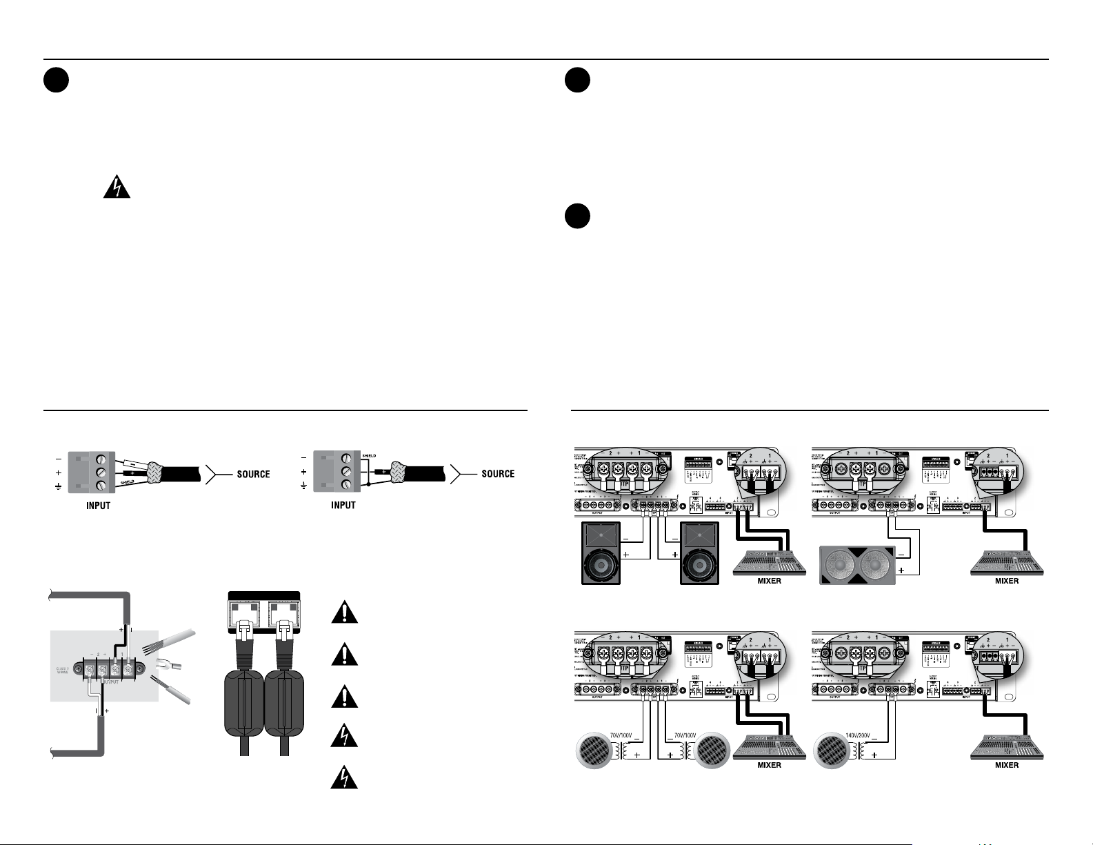
INPUT/OUTPUT WIRING
Balanced Input Wiring Unbalanced Input Wiring
Make Connections
2
WARNING: Always turn off the amplifier — by pressing and holding the Power button for 2 seconds — and disconnect the
power cord before making any wiring or installation changes.
• Turn down the level of your audio source.
• Connect the audio source to each applicable amp input using the provided 6-pin connectors.
• Connect the speakers to the amplifier outputs.
See the “Input/Output Wiring” and “Connection Diagram” sections below for reference.
Set Levels
3
• Reconnect the AC power cord to the amp, press the POWER button, then wait for the amp to boot.
• Turn your audio source up to an optimum level. Refer to all device meters and ensure that at no point in the signal chain is the
signal being clipped in any way. If any of the amplifier’s Clip indicators light yellow, reduce the source level until the Clip LEDs
no longer light.
• Turn up the amp levels.
a. To adjust all amp channel levels respectively: From the Home screen, turn the ENCODER.
b. To adjust individual amp channel levels: From the Home screen, press the channel SELECT button for the channel you
wish to adjust (the channel will become highlighted in the LCD display). Now turn the ENCODER.
For help with determining your system’s optimum gain structure (signal levels), please refer to the Crown Amplifier Application
Guide, available online at www.crownaudio.com.
CONNECTION DIAGRAMS
Low Z / Dual Output Mode Low Z / Bridge Mono Output Mode
2 1
Crown recommends using the included terminal fork connectors and two-conductor or four-conductor, heavy gauge speaker wire. You may
use terminal forks up to 10 AWG or bare wire for your output connectors. For best results, Crown recommends Panduit part #PV10-6LF-L or
equivalent terminal fork. For bare wire, it is highly recommended that output wiring is tinned. To reduce strain on input and output wiring, Crown
recommends the use of horizontal lacer bars. For best results, Crown recommends Middle Atlantic
®
part# LBP-4R90 or equivalent horizontal
lacer bar.
BLU linkIN OUTBLU linkIN OUT
NOTE: The Crown-designed output cover
does not need to be removed to connect the
output wiring. CDi DriveCore 4|300BL rear panel shown.
Attach the included ferrites to the
BLU link cables at the back of the
amplifier.
CAUTION: Never use shielded cable for output
wiring.
CAUTION: Never connect the speaker return to
the chassis of the amplifier, or damage to the
amplifier may result.
NOTE: Custom wiring should only be performed
by qualified personnel. Class 2 output wiring
is required.
Never connect the output to a power supply,
battery or power main. Electrical shock may
result.
WARNING: The third prong of the AC connector
(ground) is an important safety feature. Do not
attempt to disable this ground connection by
using an adapter or other methods.
High Z / Dual Output Mode High Z / Bridge Mono Output Mode
2 1
2 1
2 1
PN: 5075505-A
 Loading...