

Page 1
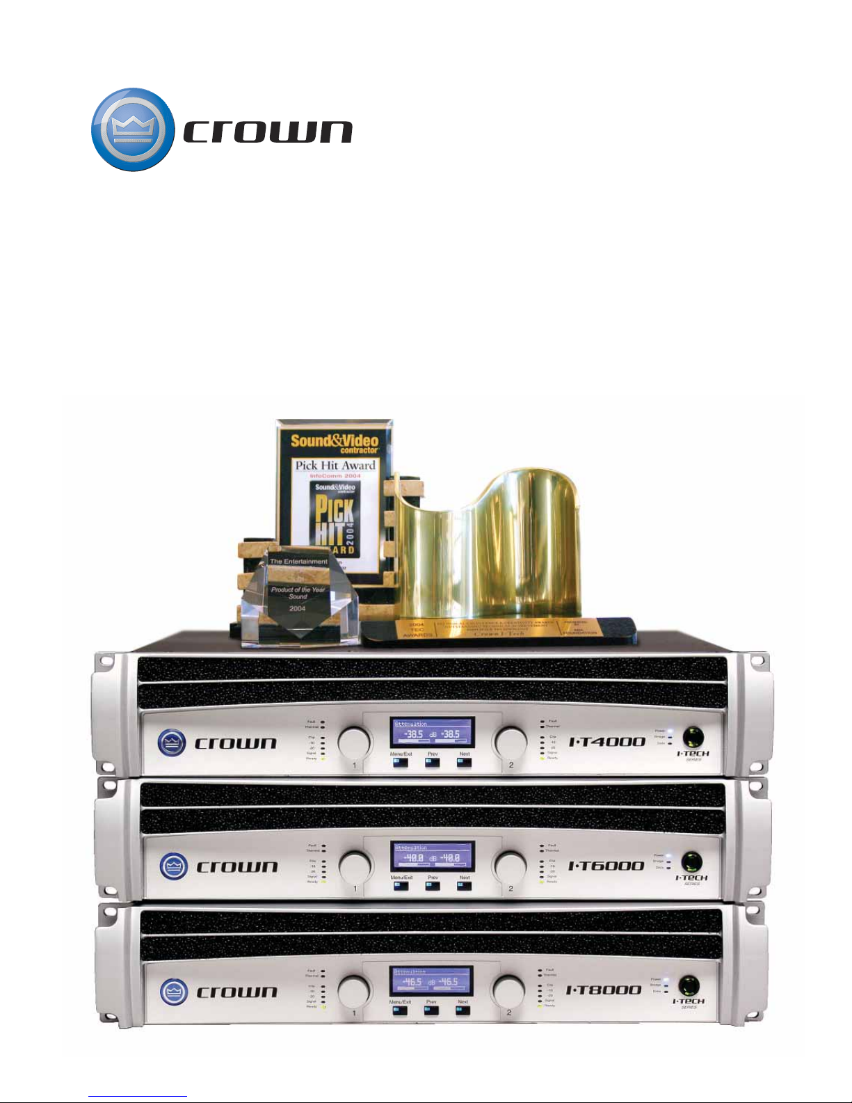
Crown® Power Amplifiers
Page 2
Page 3
CTs 2-Channel Series
CTs Multi-Channel Series
CTs Multi-Channel with CobraNet
TM
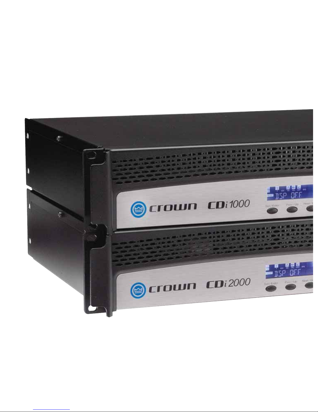
CDi Series
DSi Series
INSTALLED SOUND
Page 4
AMPLIFIERS INSTALLED SOUND
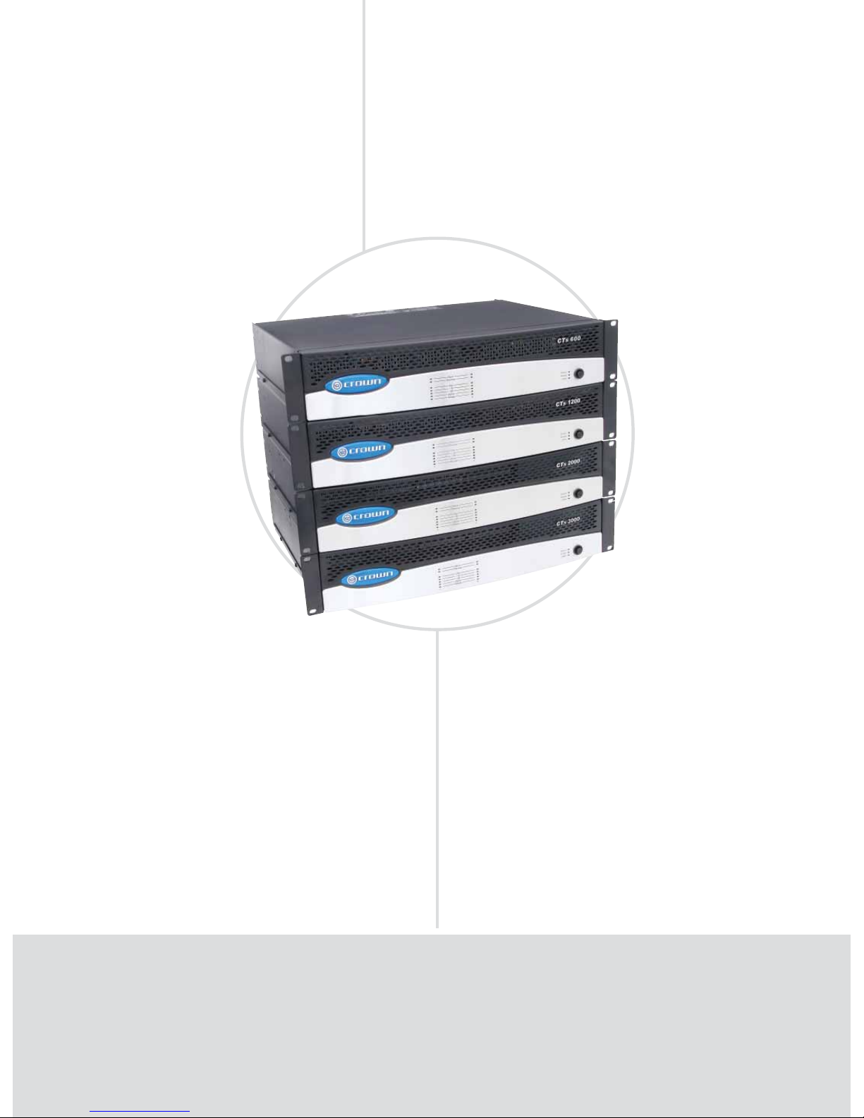
CTs Series: The New Standard
CTs 600, CTs 1200, CTs 2000, CTs 3000
Foundation
FEATURES
High power density. All two channel
models in a 2U chassis.
New Crown Switching Power Supply
for lighter weight.
Selectable “Constant-Voltage” or
low-impedance operation per channel.
100V direct outputs on all models.
Fully PIP2-compatible.
•
•
•
•
•
POWER OUTPUT*
2-ohm Dual 4-ohm Dual 8-ohm Dual 16-ohm Dual 70V Dual 100V Dual 4-ohm 8-ohm 16-ohm 100V 140V 200V
Models (per channel) (per channel) (per channel) (per channel) (per channel) (per channel) Bridge Bridge Bridge Bridge Bridge Bridge
CTs 600 150W 300W 300W 300W 300W 300W‡ 300W 600W 600W 600W‡ 600W 600W‡
CTs 1200 250W 600W 600W 300W 600W 600W‡ 500W 1,200W 1,200W 1,200W‡ 1,200W 1,200W‡
CTs 2000 1,000W 1,000W 1,000W 625W 1,000W 1,000W 2,000W 2,000W 2,000W 2,000W 2,000W 2,000W
CTs 3000 1,500W 1,500W 1,250W 625W 1,500W 1,500W 3,000W 3,000W 3,000W 3,000W 3,000W 3,000W
*Maximum average power in watts at rated THD, 20 Hz - 20 kHz. ‡With T-170V or TP-170V.
Page 5

INSTALLED SOUND
• 5
www.crownaudio.com
SPECIFICATIONS
Performance
Frequency Response (at 1 watt) 20 Hz to 20 kHz:
±0.25 dB.
Signal-to-Noise Ratio, A-weighted, below rated
power (20 Hz to 20 kHz): 105 dB.
Total Harmonic Distortion (THD) at full rated
power, from 20 Hz to 20 kHz
CTs 600 & CTs 1200: < 0.1%.
CTs 2000 & CTs 3000: < 0.35%.
Damping Factor, 10 Hz to 100 Hz: > 3000.
Crosstalk (below rated power, 20 Hz to 1 kHz):
> 80 dB.
Voltage Gain (at maximum level setting)
8/4-ohm operation, 1.4V sensitivity
CTs 600: 35:1 (31 dB).
CTs 1200: 50:1 (34 dB).
CTs 2000: 63.9:1 (36 dB).
CTs 3000: 71.4:1 (37 dB).
26 dB: 20:1 (26 dB).
70V operation, 1.4V sensitivity or
100V operation, 2.0V sensitivity: 50:1 (34 dB).
Common Mode Rejection (CMR) (20 Hz to 1 kHz,
typical): 50 dB.
Maximum Input Level: +20 dBu before input com-
pression, +32 dBu absolute maximum.
Load Impedance (safe with all types of loads):
Stereo, 2 to 16 ohms, 70V and 100V*; Mono, 4 to
16 ohms, 140V and 200V.
Input Impedance (nominal): 10 kilohms balanced,
5 kilohms unbalanced.
*CTs 600 and CTs 1200 with T-170V or TP-170V
AC Line Voltage and Frequency Configurations
Available (±10%): 120VAC, 60 Hz and 230VAC,
50 Hz.
Power Draw at Idle (120VAC mains):
CTs 600 & CTs 1200: 24W (standby mode).
CTs 2000 & CTs 3000: 35W (standby mode).
DC Output Offset (shorted input): < ±2 millivolts.
Front Panel Controls and Indicators
Power Switch: Push-on / push-off switch.
Indicators: Bridge Mode, Ready, Signal, Clip,
Thermal, Fault, Data, Power.
Back Panel Controls and Connectors
Power Cord Connector: Standard 15 amp IEC inlet.
Voltage is indicated above IEC inlet.
Reset Switch: Resets the circuit breaker that pro-
tects the power supply.
Speaker Connectors: One four-pole touch-proof
terminal strip. Accepts up to 10 AWG terminal
forks.
Input Connectors: Balanced 3-pin terminal block
connectors, one per channel, on the standard PIP2BBY module.
Channel Level Control: One 21-position detented
rotary attenuator per channel, ranging from minus
infinity (–70 dB) to 0 dB gain.
Mode Switch: Two-position switch is used to select
the amplifier’s mode of operation: Dual or BridgeMono.
Highpass Filter: One 3-position switch per channel
selects between OFF, 35 Hz and 70 Hz 3rd-order
filters.
“Y” Input Switch: When set to ON, this switch parallels the input signals of the two channels, for use
when the input signal is mono. Also can be used to
daisy-chain the signal to another amplifier.
Ventilation Grille: Front-to-rear forced airflow.
Protection
CTs Series amplifiers provide extensive protection
and diagnostic capabilities, including Thermal Level
Control (TLC), fault, low-pass filters, high-pass
filters, AC under/over voltage protection, DC output
servo, circuit breaker, in-rush limiting, and Junction
Temperature Simulation (JTS) in CTs 600/1200.
Construction
Ventilation: Front-to-rear forced airflow. Two
continuously variable speed fans direct the airflow
through the amplifier for cooling.
Dimensions: EIA Standard 19-inch (48.3-cm)
rack mount width (EIA RS-310-B), 3.5-inch
(8.9-cm) height and 14.25-inch (36.2-cm)
depth behind the mounting surface.
Weight
Net Weight:
CTs 600: 22.8 lbs. (10.3 kg).
CTs 1200: 23.4 lbs. (10.6 kg).
CTs 2000: 27.0 lbs. (12.2 kg).
CTs 3000: 27.7 lbs. (12.6 kg).
Shipping Weight;
CTs 600: 27.7 lbs. (12.6 kg).
CTs 1200: 28.3 lbs. (12.8 kg).
CTs 2000: 32.0 lbs. (14.5 kg).
CTs 3000: 32.7 lbs. (14.8 kg).
System Solutions
PIP™ LITE, PIP USP3,
PIP USP3/CN.
Regulatory Certifications
Other Applications
Note: Specifications apply to units in Dual mode with
8-ohm loads and rated input sensitivity unless otherwise specified.
C
rown’s CTs Series amplifiers provide exceptional performance, flexibility and value for installed
sound applications. CTs Series amplifiers feature independent selection of high and low impedance
operation for a specific channel, plus power levels and features that were carefully chosen to match
the requirements of fixed install design. Easy integration with HiQnet™ and CobraNet™ allows CTs
amplifiers to deliver a comprehensive lineup of monitoring and control features along with digital audio
transport for an award-winning digital audio solution.
Page 6
AMPLIFIERS INSTALLED SOUND
CTs Multi-Channel Series: The New Standard
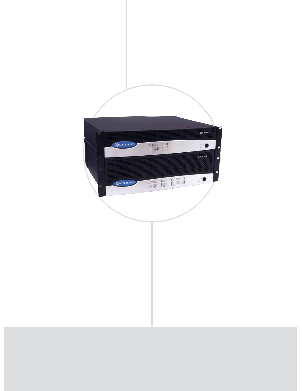
CTs 4200, CTs 8200
Flexibility
FEATURES
High power density: Four-channel model in a 2U chassis,
eight-channel model in a 3U chassis.
New Crown Switching Power Supply for lighter weight.
Selectable “Constant-Voltage” or low-impedance (4/8 ohm)
operation per channel-pair.
100V direct outputs.
New “FIT” (Fault Isolation Topology) circuitry isolates fault
conditions without affecting neighboring channels.
Accept new MC accessory modules.
•
•
•
•
•
•
POWER OUTPUT*
All channels driven 1 channel driven All channel pairs driven 1 channel pair driven
Models 4-ohm Dual 8-ohm Dual 70V Dual 4-ohm Dual 8-ohm Dual 70V Dual 8-ohm Bridge 16-ohm Bridge 100V Bridge 8-ohm Bridge 16-ohm Bridge 100V Bridge
CTs 4200 260W 180W 220W† 270W 220W 245W† 520W 400W 220W† 560W 440W 245W
†
CTs 8200 200W 160W 185W† 270W 220W 230W† 400W 320W 185W† 540W 440W 230W
†
*
Maximum average power in watts at 1kHz at 0.1% THD.
†Constant Voltage full-bandwidth power ratings support 100 Hz to 20 kHz due to automatic high-pass filters.
Page 7

INSTALLED SOUND
• 7
www.crownaudio.com
SPECIFICATIONS
Performance
Frequency Response (at 1 watt, 20 Hz - 20 kHz):
±0.5 dB.
Phase Response (at 1 watt, 10 Hz - 20 kHz): ±35°.
Signal to Noise Ratio (below rated power, 20 Hz to
20 kHz): 100 dB unweighted.
Total Harmonic Distortion (THD) at 1 watt, from
20 Hz to 20 kHz: < 0.05%.
Intermodulation Distortion (IMD) 60 Hz and 7 kHz
at 4:1, from 163 milliwatts to full bandwidth power:
< 0.05% (typical).
Damping Factor: 10 Hz to 400 Hz: >180.
Crosstalk (below rated power, 20 Hz to 1 kHz):
> 80 dB.
Common Mode Rejection (CMR) (20 Hz to 1 kHz):
> 50 dB.
DC Output Offset (shorted input): < ±5 mV.
Input Impedance (nominal): 20 kilohms balanced,
10 kilohms unbalanced.
Maximum Input Level (before input compression):
+20 dBu.
Load Impedance: (Note: Safe with all types of
loads)
Stereo: 4/8 and 25 ohms (70V).
Bridge Mono: 8/16 and 50 ohms (100V).
Voltage Gain (at maximum level setting), 1.4V
sensitivity,
4/8 Ohm Operation: 20:1 (26 dB).
70V Operation: 50:1 (34 dB).
100V Operation: 71.4:1 (37 dB).
AC Line Voltage and Frequency Configurations
Available (±10%): 120V/60 Hz, 220/230/240V/50
Hz.
Power Draw at Idle (120VAC mains, all channels in
4/8 ohm mode): 58W.
C
rown’s CTs Multi-Channel Series offers wide flexibility for a wide range of installed sound applications. CTs Multi-Channel Series amplifiers offer independent selection of high- and low-impedance
operation for each channel pair, making these amps ideal for multi-zone installations.
Power Draw at Idle (120VAC mains, all channels in
70V mode): 77W.
Front Panel Controls and Indicators
Indicators: Bridge, Ready, Signal, Clip, Thermal,
Fault, Data, Power.
Power Switch: Amplifier is on when the switch is
in the IN position.
Back Panel Controls and Connectors
AC Power Cord Connector: IEC inlet, type 320;
100/120VAC units: 15A.
220/230/240VAC units: 10A.
Voltage is indicated above IEC inlet.
Output Connectors: One four-pole terminal strip
for every two channels with touch-proof cover.
Accepts up to 10 AWG terminal forks.
Accessory Panel: CTs 4200 accepts an optional
VCA-MC4A module. CTs 8200 accepts an optional
VCA-MC8 module.
Channel Level Controls: One 21-position detented
rotary potentiometer per channel, ranging from
infinity (–70 dB) to 0 dB attenuation.
Input Connectors: Removable Phoenix-style barrier
connectors for balanced input.
Mode Switch: Used on each consecutive pair of
channels, this four-position switch is used to select
the amplifier’s mode of operation: Dual 8/4 ohms,
Dual 70V, Bridge-Mono 16/8 ohms, and BridgeMono 100V.
Protection
CTs Multi-channel Series amplifiers provide
extensive protection and diagnostic capabilities,
including Thermal Level Control (TLC), fault, FIT
protected circuitry, AC under/over voltage protection, power fuse, and in-rush limiting
Construction
Ventilation: Front-to-rear forced airflow.
Continuously variable speed fans (four in the
CTs 8200, one in the CTs 4200) direct the airflow
through the amplifier for cooling.
Dimensions
CTs 4200: EIA Standard 19-inch (48.3-cm) rack
mount width (EIA RS-310-B), 3.5-inch (8.9-cm)
height and 16.25-inch (41.3-cm) depth behind the
mounting surface.
CTs 8200: EIA Standard 19-inch (48.3-cm) rack
mount width (EIA RS-310-B), 5.25-inch (13.3-cm)
height and 16.25-inch (41.3-cm) depth behind the
mounting surface.
Weight
Net Weight:
CTs 4200: 27 lb 8 oz (12.5 kg);
CTs 8200: 36 lb 6 oz (16.5 kg).
Shipping Weight:
CTs 4200: 32 lb (14.5 kg).
CTs 8200: 47 lb (21.3 kg).
System Solutions
VCA-MC4A: VCA module for CTs 4200A.
VCA-MC8: VCA module for CTs 8200.
VCA modules allow remote volume control.
Accessories
Wall-mount level control panels for use with
VCA module:
1-VCAP: 1-gang panel with 1 VCA channel
volume control.
4-VCAP: 2-gang panel with 4 VCA channel
volume controls.
Regulatory Certifications
Other Applications
Page 8

CobraNet
TM
Capable
FEATURES (input module)
100 Mbps Ethernet single-plug solution for CobraNet audio,
and HiQnet™ control and monitoring.
Analog audio inputs allow CobraNet network audio input,
CobraNet audio backup, or a hardwire emergency override
of CobraNet audio.
24 bit digital to analog conversion with 32 bit, fl oating point
DSP processing.
Firmware upgrades via the network.
10 user selectable presets.
Reliable FLASH memory backup of all parameters.
•
•
•
•
•
•
POWER OUTPUT*
All channels driven 1 channel driven All channel pairs driven 1 channel pair driven
Models 4-ohm Dual 8-ohm Dual 70V Dual 4-ohm Dual 8-ohm Dual 70V Dual 8-ohm Bridge 16-ohm Bridge 100V Bridge 8-ohm Bridge 16-ohm Bridge 100V Bridge
CTs 4200USP/CN
260W 185W 220W
†
270W 220W 245W† 520W 400W 220W† 560W 440W 245W
†
CTs 8200USP/CN
200W 160W 185W† 270W 220W 230W† 400W 320W 185W† 540W 440W 230W
†
*Maximum average power in watts at 1kHz at 0.1% THD.
†Constant Voltage full-bandwidth power ratings support 100 Hz to 20 kHz due to automatic high-pass fi lters.
CTs Multi-Channel Series: With CobraNet
CTs 4200USP/CN, CTs 8200USP/CN
AMPLIFIERS INSTALLED SOUND
Page 9
INSTALLED SOUND
• 9
www.crownaudio.com
D/A and A/D Conversion: 24 bit.
Latency:
DSP processing: 1 ms or 1000 µs.
D/A Conversion: 250 µs.
A/D Conversion: 250 µs.
Amplifier: 100 µs.
Total: 1.6 ms or 1600 µs.
Dynamic Range: 103 dB typical (A-weighted,
20Hz–20kHz, audio sourced from muted CobraNet
channel).
Distortion: < 0.1% THD+N, 20Hz–20kHz.
Frequency Response: ± 0.5 dB, 20Hz–20kHz.
Input/Output Monitor Accuracy: Typically ±1dB.
Maximum Input Level: + 20 dBu.
Regulatory Certifications
Other Applications
IQ Data Indicator: Flashes when the module
receives a valid command that is addressed to the
CTs 4200 USP/CN and CTs 8200USP/CN.
Switches:
Reset/Preset Switch: Used to change presets,
restore settings to factory default or restore all the
presets to the factory defaults. During operation of
the switch, the Data indicator flashes as an aid to
the user. Accessible with a straightened paper clip
through the rear panel, the switch selects the next
user preset if pressed for less than 2 seconds, and
resets the module to preset “0” if pressed for more
than 2 seconds.
General:
Memory Backup: Non-volatile FLASH memory for
backup of run-time parameters, presets, and program storage.
Communications: 100Mb Fast Ethernet conforming
to IEEE 802.3.
Overall Audio Performance:
DSP Processing: Two processors, 32 bit, Floating
Point, 724 µs latency.
SPECIFICATIONS
USP/CN CobraNet Module Specifications
(for amplifier specifications, see the CTs MultiChannel Series pages)
Connectors:
AUX Connector: Configurable for AUX input, AUX
output and Listen Bus. Listen Bus is also supported
through CobraNet.
Network Connector: The dual RJ45 CobraNet connectors allow a Primary & Secondary connection to
the 100Mb Ethernet network. Should the Primary
connection lose link activity with the network,
the input module will automatically switch to the
Secondary connection to ensure uninterrupted
audio and control. The indicators on the RJ45 connectors display network information concerning the
Ethernet and CobraNet connections.
Indicators:
Preset Indicator: Signals the number of the cur-
rent preset, if active, by flashing a series of flashes
equal to the current preset number.
T
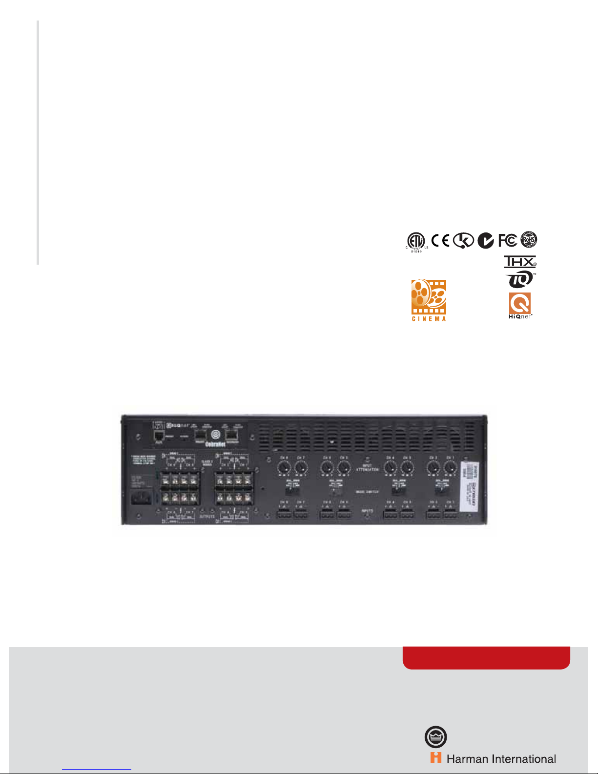
he Crown® CTs 4200USP/CN and CTs 8200USP/CN power amplifiers have an integrated 3rd genera-
tion, DSP-based input module. It connects the amplifier to a 100 Mbps Ethernet network allowing it
to be remotely controlled and monitored via System Architect™ software. In addition, the input module
allows the transport of real-time digital audio via CobraNet™ over the same Ethernet network. The
amplifi ers connect to a HiQnet™ audio control/monitor network using standard 100 Mbps Ethernet
hardware (switches, Network Interface Cards, and cables). CobraNet™ audio is available over the same
100 Mbps Ethernet network, providing a simple-to-install, single-plug solution for audio distribution,
control, and monitoring.
CTs 8200USP/CN Back Panel (note USP/CN CobraNet™ module at top left)
Page 10
AMPLIFIERS INSTALLED SOUND
CDi Series: 2/4/8 Ohm, 70V/100V per channel
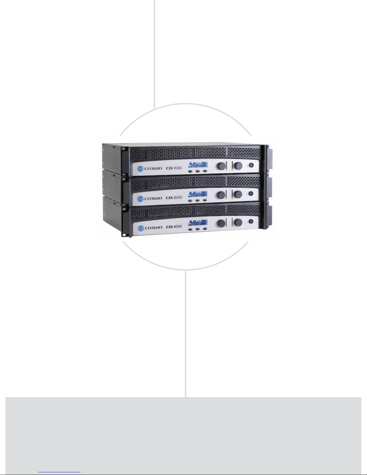
CDi 1000, CDi 2000, CDi 4000
Versatility
FEATURES
Onboard digital signal processing includes crossovers,
EQ fi lters, delay, and output limiting.
Computer connectivity via USB allows fast setup and
confi guration with HiQnet™.
Barrier strip outputs, removable Phoenix-style input.
Extremely versatile, handling a wide range of speaker
impedances and outputs.
Switch-mode universal power supply.
Speaker presets for crossover frequencies, EQ, limiting,
compression, delay, and subharmonic synthesis.
•
•
•
•
•
•
POWER OUTPUT*
2-ohm Dual 4-ohm Dual 8-ohm Dual 70V Dual 4-ohm 100V‡ Dual 140V Bridge
Models (per channel) (per channel) (per channel) (per channel) Bridge (per channel)
CDi 1000 700W** 500W 275W 500W 1,400W** 500W 1,000W
CDi 2000 1,000W** 800W 475W 800W 2,000W** 800W 1,600W
CDi 4000 1,600W** 1,200W 650W 1,000W 3,200W** 1,000W 2,000W
*Maximum average power in watts at 1 kHz at 0.5% THD. **With 1% THD. ‡100Vp
Page 11

INSTALLED SOUND
• 11
www.crownaudio.com
SPECIFICATIONS
Performance
Output Power: See power charts on previous page.
Voltage Gain at 1kHz, 8 ohm rated output:
CDi 1000: 30.5 dB.
CDi 2000: 32.9 dB.
CDi 4000: 34.2 dB.
Frequency Response: +0/–1 dB from 20 Hz to 20
kHz at 1 watt into 4 ohms.
Load Impedance: Safe with all types of loads.
Rated for 2 to 8 ohms in Stereo mode, 4 to 16
ohms in Bridge-Mono mode.
Sensitivity: 1.4V.
Signal to Noise Ratio (below rated 8-ohm power
at 1 kHz): 100 dB (A weighted).
Damping Factor: Better than 500 from 20 Hz to
400 Hz.
Crosstalk: > 70 dB below rated power, 20 Hz to
1 kHz.
Input Stage: Input is electronically balanced and
employs precision 1% resistors.
Input Impedance (nominal): 20 k ohms, balanced;
10 k ohms, unbalanced.
Maximum Input Signal: +22 dBu typical.
AC Line Voltage and Frequency Configurations
Available: 100V, 120V, 220-240V, 50/60 Hz.
AC Line Current:
CDi 1000: 11.50A.
CDi 2000: 11.93A.
CDi 4000: 11.75A.
At Idle: Draws no more than 45 watts.
Operating Temperature: 0° C to 40° C at 95%
relative humidity (non-condensing).
DSP Section
Input EQ: 6 parametric fi lters per channel with
adjustable Q, ±15 dB boost/cut. Also adjustable
high and low shelving fi lters. This 8-fi lter EQ
section can be bypassed.
Crossover Filters: Highpass and lowpass per
channel. Butterworth 6/12/18/24 dB per octave
and Linkwitz-Riley 24/48 dB per octave. Also
includes ±15 dB bandpass gain and polarity
control.
Output EQ: 8 parametric fi lters per channel with
adjustable Q, ±15 dB boost/cut. This 8-fi lter EQ
section can NOT be bypassed. Filters are enabled
individually.
Delay: Up to 50 msec total delay per channel.
Output Limiter: Prevents clipping and protects
loudspeakers. Choice of –3, –6, or –12 dB
threshold per channel.
Presets: 20 presets. 19 are user-defi nable.
Front Panel Controls and Indicators
Level: Detented rotary level control, one per chan-
nel.
Power Switch: On/off switch applies AC power to
the amplifier.
Sel/Prev/Next Buttons: Three buttons near the
LCD screen are used to access menu items and
front panel lockout.
LCD Screen: Backlit liquid crystal display shows
speaker presets and signal processing.
Signal Indicator: Green LED, one per channel,
illuminates when a very low-level signal is present
at input.
–10 Indicator: Green LED flashes when output
signal exceeds –10 dB below clip.
–20 Indicator: Green LED flashes when output
signal level exceeds –20 dB below clip.
Ready Indicator: Green LED, one per channel,
illuminates when the amplifier is ready to produce
audio.
Clip Indicator: Red LED, one per channel, turns on
at the threshold of audible distortion.
Temp Indicator: Red LED, one per channel, illuminates under excessive temperature conditions.
Power Indicator: Blue LED illuminates when the
amplifier has been turned on and has power.
Rear Panel Controls and Connectors
AC Line Connector: NEMA 5-15P (15A).
Input Connector: Two 3-pin removable Phoenix-
type connectors each accept a balanced line-level
input signal.
Output Connectors: 4-position barrier strip with
connectors for dual loudspeakers or bridge-mono
loudspeaker. Dual connectors work with 2-8 ohm
or 70V loads. Bridge-mono connectors work with
4-8 ohm or 140V loads.
HiQnet USB Connector: Type B, connects to a
USB port on a PC.
Protection
CDi-Series amplifiers are protected against shorted,
open or mismatched loads; overloaded power
supplies; excessive temperature; chain destruction
phenomena; excessive output current, and input
overload damage. They also protect loudspeakers
from input/output DC, large or dangerous DC offsets and turn-on/turn-off transients
Construction
Chassis: Steel.
Cooling: Proportional speed fan with front-to-rear
airflow.
Dimensions: EIA Standard 19-in. (48.3-cm) rack
mount width (EIA RS-310-B), 3.5 in. (8.9 cm) high
and 12.25 in. (31.11 cm) deep behind mounting
surface.
Net Weight: 19 lb (8.6 kg).
Shipping Weight: 22 lb (10.0 kg).
Regulatory Certifications
Note: All measurements apply to all models of CDi
Series amplifiers in stereo mode with 8-ohm loads and
an input sensitivity of 26 dB gain, 1 kHz at rated power
unless other otherwise specified. Specifications for
units supplied outside the U.S.A. may vary slightly at
different AC voltages and frequencies.
T
he CDi Series of Crown® amplifiers are designed for installed sound applications. The series includes
three models which are identical except for output power: CDi 1000, CDi 2000 and CDi 4000. All are
rugged and lightweight, and offer unmatched value in their class. CDi-Series amplifiers feature an LCD
screen with DSP speaker presets. Other features include a switch-mode universal power supply, useful
function indicators, proportional-speed fan-assisted cooling, removable Phoenix-style inputs, barrier
strip outputs for low-Z or 70V/140V loads, short-circuit protection and more.
Page 12
One-touch
Performance
FEATURES
Intuitive front-panel LCD screen, automatic presets for popular
JBL speaker systems for quick, easy confi guration.
Onboard digital signal processing includes crossovers, EQ fi lters,
delay, and output limiting.
Computer connectivity via USB allows fast setup and confi guration with HiQnet™.
Barrier strip outputs, removable Phoenix-style input.
All models are THX
®
-approved.
•
•
•
•
•
POWER OUTPUT
2-ohm Dual 4-ohm Dual 8-ohm Dual 4-ohm 8-ohm
Models (per channel) (per channel) (per channel) Bridge Bridge
DSi 1000 700W** 475W* 275W* 1,400W** 950W*
DSi 2000 1,000W** 800W* 475W* 2,000W** 1,600W*
DSi 4000 1,600W** 1,200W* 650W* 3,200W** 2,400W*
*Maximum average power in watts at 1 kHz at 0.5% THD. **With 1% THD.
DSi Series: 2, 4, 8 ohm
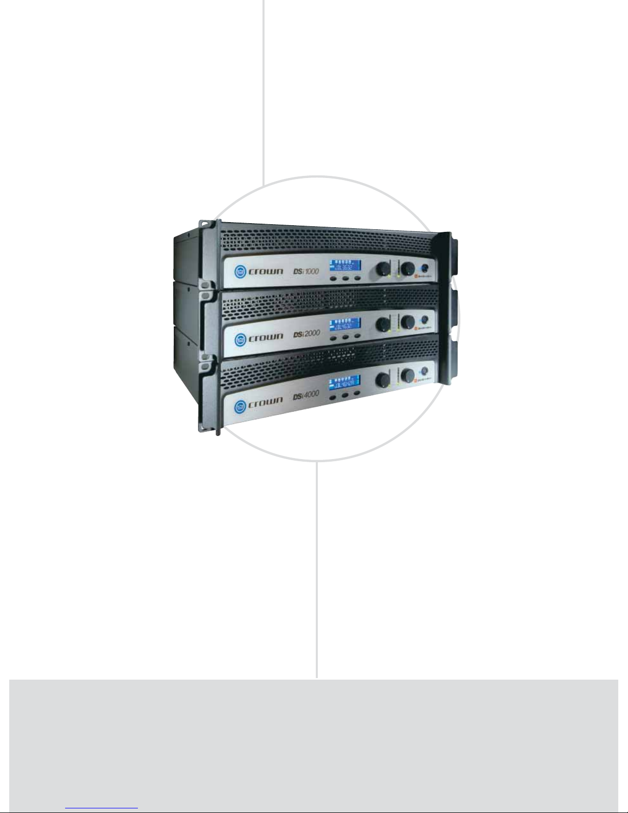
DSi 1000, DSi 2000, DSi 4000
AMPLIFIERS INSTALLED SOUND
Page 13

INSTALLED SOUND
• 13
www.crownaudio.com
SPECIFICATIONS
Performance
Voltage Gain at 1kHz, 8 ohm rated output:
DSi 1000: 26 dB.
DSi 2000: 26 dB.
DSi 4000: 26 dB.
Frequency Response: +0/–1 dB from 20 Hz to 20
kHz at 1 watt into 4 ohms.
Load Impedance: Safe with all types of loads.
Rated for 2 to 8 ohms in Stereo mode, 4 to 16
ohms in Bridge-Mono mode.
Sensitivity:
At 8 ohm rated output:
DSi 1000: 1.4V.
DSi 2000: 1.4V.
DSi 4000: 1.4V.
At 4 ohm rated output:
DSi 1000: 1.3V.
DSi 2000: 1.2V.
DSi 4000: 1.3V.
At 2 ohm rated output:
DSi 1000: 1.1V.
DSi 2000: 1.0V.
DSi 4000: 1.0V.
Signal to Noise Ratio (below rated 8-ohm power
at 1 kHz): 100 dB (A weighted).
Damping Factor: Better than 500 from 20 Hz to
400 Hz.
Crosstalk: > 70 dB below rated power, 20 Hz to 1
kHz, A-weighted.
Input Stage: Input is electronically balanced and
employs precision 1% resistors.
Input Impedance (nominal): 20 k ohms, balanced;
10 k ohms, unbalanced.
Maximum Input Signal: +22 dBu typical.
AC Line Voltage and Frequency Configurations
Available: 100V, 120V, 220-240V, 50/60 Hz.
AC Line Current:
DSi 1000: 11.56A.
DSi 2000: 11.93A.
DSi 4000: 11.75A.
At Idle: Draws no more than 45 watts.
Operating Temperature: 0° C to 40° C at 95%
relative humidity (non-condensing).
DSP Section
Input EQ: 6 parametric fi lters per channel with
adjustable Q, ±15 dB boost/cut. Also adjustable
high and low shelving fi lters. This 8-fi lter EQ
section can be bypassed.
Crossover Filters: Highpass and lowpass
per channel. Butterworth 6/12/18/24 dB per
octave, Linkwitz-Riley 24/48 dB per octave. Also
includes ±15 dB bandpass gain and polarity
control.
Output EQ: 8 parametric fi lters per channel with
adjustable Q, ±15 dB boost/cut. This 8-fi lter EQ
section can NOT be bypassed. Filters are enabled
individually.
Output Limiter: Prevents clipping and protects
loudspeakers. Choice of –3, –6, or –12 dB
threshold per channel.
Delay: Up to 50 msec total delay per channel.
Presets: 20 presets. One is “DSP OFF.” Fifteen
are factory-set for JBL Cinema systems. Four
are user-defi nable.
Front Panel Controls and Indicators
Level: Detented rotary level control, one per chan-
nel.
Power Switch: On/off switch applies AC power to
the amplifier.
Sel/Prev/Next Buttons: Three buttons near the
LCD screen are used to access menu items and
front panel lockout.
LCD Screen: Backlit liquid crystal display shows
speaker presets and signal processing.
Signal Indicator: Green LED, one per channel,
illuminates when a very low-level signal is present
at input.
–10 Indicator: Green LED flashes when output
signal exceeds –10 dB below clip.
–20 Indicator: Green LED flashes when output
signal level exceeds –20 dB below clip.
Ready Indicator: Green LED, one per channel,
illuminates when the amplifier is ready to produce
audio.
Clip Indicator: Red LED, one per channel, turns on
at the threshold of audible distortion.
Temp Indicator: Red LED, one per channel, illuminates under excessive temperature conditions.
Power Indicator: Blue LED illuminates when the
amplifier has been turned on and has power.
Back Panel Controls and Connectors
AC Line Connector: NEMA 5-15P (15A).
Input Connector: Two 3-pin removable Phoenix-
type connectors each accept a balanced line-level
input signal.
Output Connectors: 4-position barrier strip with
connectors for dual loudspeakers or bridge-mono
loudspeaker.
HiQnet USB Connector: Type B, connects to a
HiQnet network.
HD-15 Connector: For cinema I/O compatibility
with DSi-8M System Monitor.
Protection
DSi-Series amplifiers are protected against shorted,
open or mismatched loads; overloaded power
supplies; excessive temperature; chain destruction
phenomena; excessive output current, and input
overload damage. They also protect loudspeakers
from input/output DC, large or dangerous DC offsets and turn-on/turn-off transients
Construction
Chassis: Steel.
Cooling: Proportional speed fan with front-to-rear
airflow.
Dimensions: EIA Standard 19-in. (48.3-cm) rack
mount width (EIA RS-310-B), 3.5 in. (8.9 cm) high
and 12.25 in. (31.11 cm) deep behind mounting
surface.
Net Weight: 19 lb (8.6 kg).
Shipping Weight: 22 lb (10.0 kg).
Regulatory Certifications
Other Applications
Note: All measurements apply to all models of CDi
Series amplifiers in stereo mode with 8-ohm loads and
an input sensitivity of 26 dB gain, 1 kHz at rated power
unless other otherwise specified. Specifications for
units supplied outside the U.S.A. may vary slightly at
different AC voltages and frequencies.
T
he Crown® DSi Series of power amplifiers provides onboard digital signal processing
including crossovers, EQ filters, delay and output limiting. The intuitive front panel LCD
screen guides installers through a setup process—featuring presets for popular JBL speaker
systems—to make confi guration quick and easy. At the touch of a button, Crown’s DSi amplifi ers deliver perfectly matched performance with each award-winning JBL loudspeaker system,
making this the ultimate installed-sound solution.
Page 14
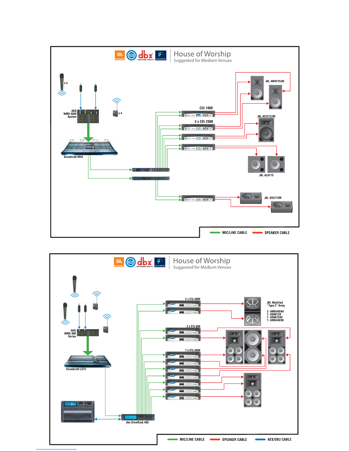
INSTALLED SOUND
Product Applications
CDi 2000
BSS FDS-336 Loudspeaker
Management System
dbx DriveRack 220V
dbx 480 Remote Unit
for DriveRack 480
Page 15
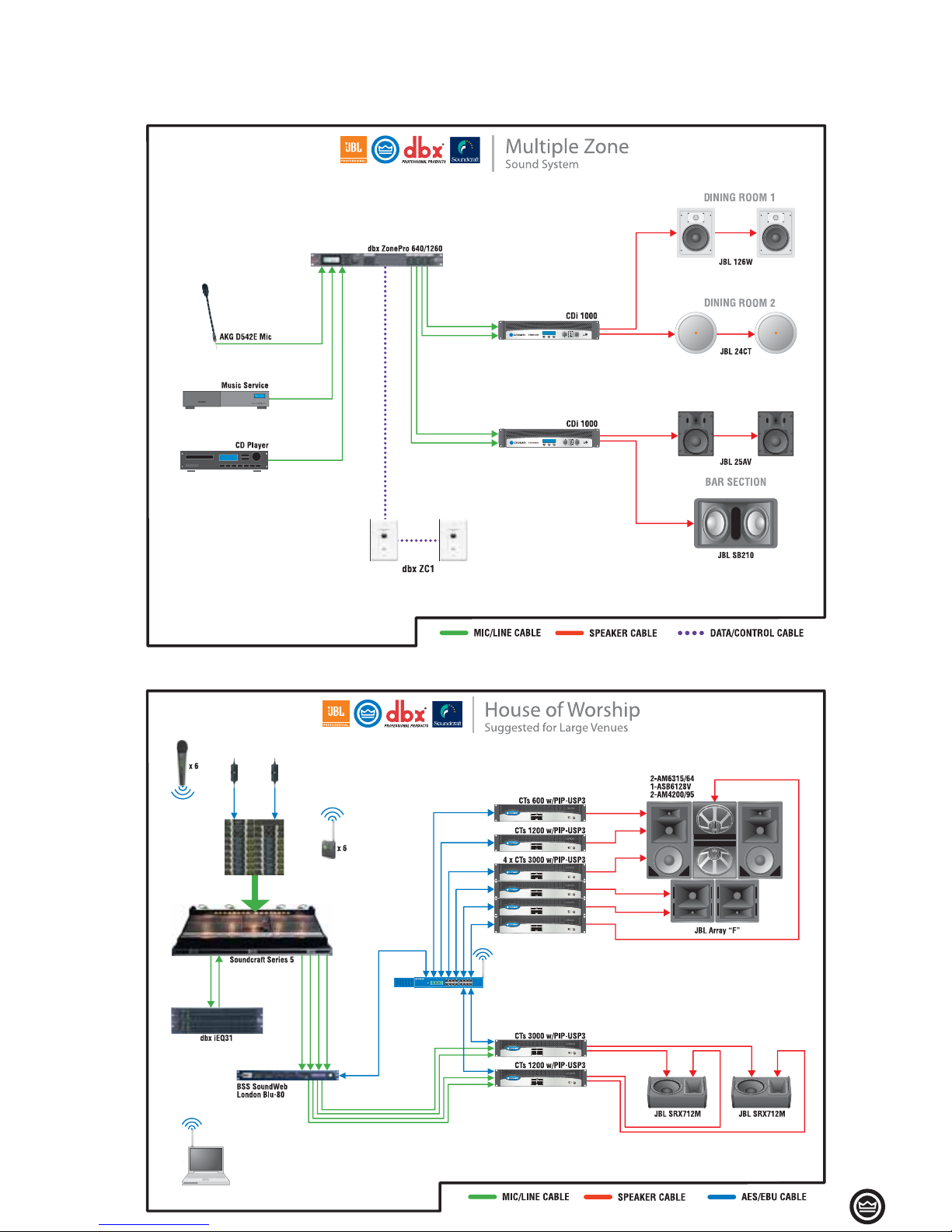
• 15
INSTALLED SOUND
Product Applications
Network Switch
Page 16
Page 17
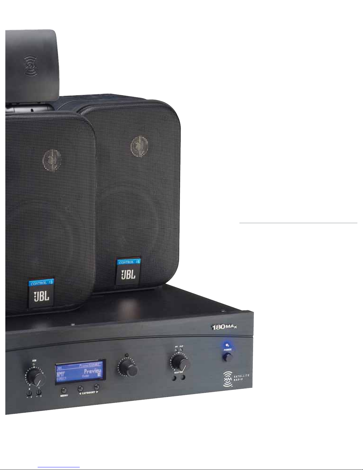
Preamplifier-Mixers
Amplifiers
Mixer-Amplifiers
XM Business Music Systems
COMMERCIAL AUDIO
Page 18
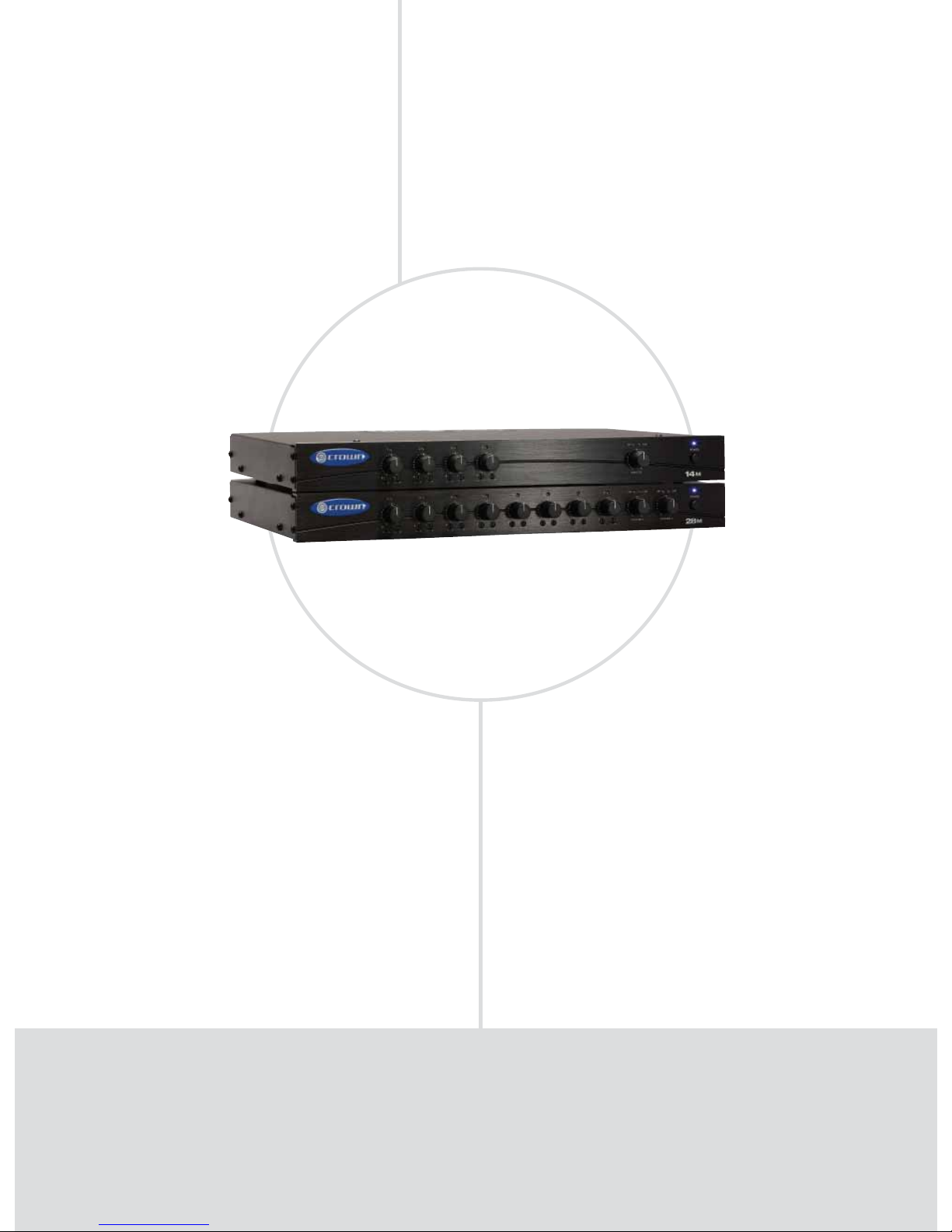
Adaptable
FEATURES
4 or 8 inputs, 1 or 2 output channels.
Ideal for commercial and industrial use.
Balanced Phoenix-type mic/line inputs; RCA inputs.
Balanced Phoenix-type line outputs.
Any input can be sent to any output.
Priority muting.
Independent bass and treble controls for each input.
•
•
•
•
•
•
•
Model Inputs System Zones
14M 4 Single-zone
28M 8 Two-zone
COMMERCIAL AUDIO PREAMPLIFIER-MIXERS
14M, 28M
Page 19

COMMERCIAL AUDIO
• 19
www.crownaudio.com
SPECIFICATIONS
Performance
Frequency Response (at line out): 20 Hz to 20
kHz +/- 1 dB.
Signal to Noise Ratio (master volume at minimum):
100 dB.
THD: 0.05% typical with 800 mV balanced input,
1V output.
Input Sensitivity (volts RMS for full output at
maximum gain):
Balanced mic inputs: 3 mV.
Balanced line inputs: 800 mV.
RCA connectors: 400 mV.
Input Impedance (nominal):
Mic: 400 ohms.
Line: 100 kilohms.
RCA: 50 kilohms.
Crosstalk (all controls at “10”): –50 dB at 1kHz.
Line Output Level (nominal): 1.2 V into 10
kilohms.
Phantom Power: 15 VDC.
AC Line Voltage and Frequency Configurations
Available:
100V 50/60 Hz.
120V 60 Hz.
220V 50/60 Hz.
230V 50/60 Hz.
240V 50/60 Hz.
Operating Temperature/Humidity:
0° C to 40° C
at 95% relative humidity (non-condensing).
Storage Temperature: –20° C to 85° C.
Front Panel Controls and Indicators
Power Switch: Push-button on-off switch. The
power switch does not affect the 24V DC auxiliary power input.
Input Volume Controls: Microphone/line, four
in 14M, eight in 28M. Detented potentiometers
with knobs.
Tone Controls:
Bass and Treble non-detented
potentiometers on each input channel. Bass ±10
dB at 100 Hz, Treble ±10 dB at 10 kHz.
Power Indicator: Blue LED indicates power on.
Input Signal Presence Indicator:
Green LED, one
for each input channel, illuminates when input
signal exceeds –24 dBu (line) or –70 dBu (mic).
Output Signal Presence Indicator: Green LED,
one for each output channel, illuminates when
output signal level exceeds 100 mV.
Clip Indicators:
Red LED, one per output chan-
nel. Illuminates at threshold of audible distortion.
Output Volume Controls: One per output channel.
Detented potentiometer with knob.
Back Panel Controls and Connectors
Fuse: Protects the power supply.
AC Power Inlet: Detachable IEC.
Auxiliary Power Input: 2-position terminal strip
for 24 VDC (±10%) backup power. Accepts up to
10 AWG terminal forks.
Mixer Config Switch: A DIP switch with two
functions:
1. Assigns an input as the priority input for
each output, thereby temporarily muting the
remaining inputs. Muting is activated by contact
closure.
2. Global enable switch for phantom power.
Does not affect RCA inputs. Default position is
off.
Priority Connector: 3-pin Phoenix-type connector allows Input 1 or Input 5 (28M only) to mute
other input signals by contact closure.
Input Routing Switch (28M only): DIP switches
that assign each input signal to each output. Two
switches per input.
Line Out Connector: One 3-pin balanced Phoenix-type connector per output channel. Level
controlled by master volume control.
Input Connectors:
Mic/Line Connector: 3-pin
Phoenix-type, balanced, one per input channel.
Dual RCA Input Connector: For stereo music
signals, unbalanced, summed together, two
connectors per input channel.
Mic/line Switch: Selects mic-level or line-level
signals. One switch for each balanced input
Included Accessories
Power cord.
Detachable rack ears.
Phoenix-type connectors.
Spade lugs.
Dimensions
Width (without rack ears): 17.3 in. (43.8 cm).
Width (with rack ears): EIA Standard 19 in. (48.3-
cm) W (EIA RS-310-B).
Height (front panel): 1.7 in. (4.3 cm).
Height (including feet): 2.3 in. (5.9 cm).
Depth (front panel to back panel): 10.7 in. (27.2
cm).
Depth (front of knobs to back of non-touch cover):
12.4 in. (31.4 cm).
Weight
Net Weight:
14M: 8.7 lb (3.9 kg).
28M: 8.7 lb (3.9 kg).
Shipping Weight:
14M: 14 lb (6.4 kg).
28M: 14 lb (6.4 kg).
Regulatory Certifications
Note: All measurements are related to 120VAC units 60
Hz unless other otherwise specified. Specifications for
units supplied outside the U.S.A. may vary slightly at
different AC voltages and frequencies.
T
he Crown® 14M and 28M are high-value mixers for commercial and industrial audio. The mixers
are part of Crown’s Commercial Audio Series, which also includes mixer-amplifiers and power
amplifiers. These low-cost units provide all necessary features in a simple building-block format. Some
applications include schools, hospitals, factories, restaurant/retail, houses of worship, fitness facilities,
A/V boardrooms, correctional facilities, and small offices. Typical uses are paging, background music,
security and evacuation instructions. Input routing allows each input to be assigned to any output. You
can add more mixers for more inputs, or add more power amps (or mixer-amps) to handle more zones.
Other features include priority muting and phantom power.
Page 20
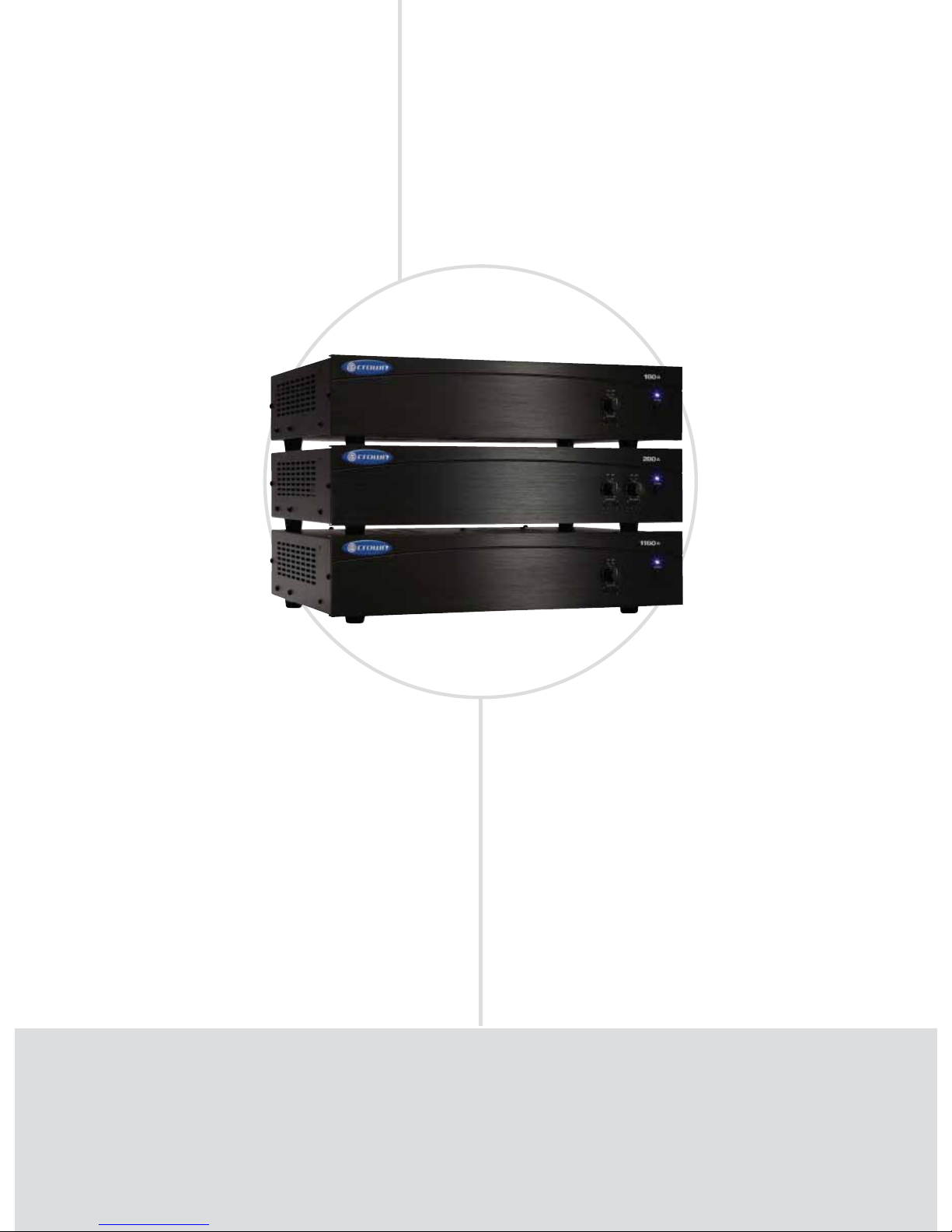
COMMERCIAL AUDIO AMPLIFIERS
180A, 280A, 1160A
Power Zone
FEATURES
Ideal for commercial and industrial use.
Balanced Phoenix-type line inputs; touch-proofed screw-terminal
speaker outputs.
Advanced protection system includes output current limiting,
DC protection, circuit breaker/fuse, and thermal protection.
1 or 2 inputs; 1 to 2 amplifi er output channels.
•
•
•
•
POWER OUTPUT*
Models 4-ohm 70V/100V Inputs System Zones
180A 80W 80W 1 Single-zone
280A 80W 80W 2 Two-zone
1160A 160W 160W 1 Single-zone
*Minimum guaranteed power in watts at 1 kHz with 0.5% THD.
Page 21

COMMERCIAL AUDIO
• 21
www.crownaudio.com
T
he Crown® 180A, 280A and 1160A are high-value amplifiers for commercial and industrial audio.
They provide 4-ohm and constant-voltage outputs (70V and 100V). The amps are part of Crown’s
Commercial Audio Series, which also includes mixers and mixer-amps. These low-cost units provide
all necessary features in a simple building-block format.
SPECIFICATIONS
Performance
Frequency Response (at 1 watt from 4-ohm tap):
70 Hz to 19 kHz +/- 1 dB.
Frequency Response (at line out): 20 Hz to 20 kHz
+/- 1 dB.
Power Bandwidth (at 4-ohm tap, 2 dB below
maximum 1 kHz power): 50 Hz to 20 kHz with
< 0.5% THD
Signal to Noise Ratio (ref. to rated power, master
volume at minimum): 85 dB.
DC Output Offset: < ±5 mV.
THD: Less than 0.5% at rated power at 1 kHz.
Input Sensitivity (for full output at maximum
gain): 800 mV.
Input Impedance (nominal): 100 kilohms.
Minimum Load Impedance:
100V output: 160 ohms
70V output: 80 ohms
4-ohm output: 4/8 ohms
Crosstalk (all controls at “10”): –70 dB at 1kHz.
Line Output Level (nominal): 1V into 10 kilohms.
AC Line Voltage and Frequency Configurations
Available:
100V 50/60 Hz.
120V 60 Hz.
220V 50/60 Hz.
230V 50/60 Hz.
240V 50/60 Hz.
Operating Temperature/Humidity: 0° C to 40° C
at 95% relative humidity (non-condensing).
Storage Temperature: –20° C to 85° C.
Front Panel Controls and Indicators
Power Switch: Push-button on-off switch. The
power switch does not affect the 24V DC auxiliary
power input.
Power Indicator: Blue LED indicates power on.
Output Signal Presence Indicator: Green LED,
one for each output channel, illuminates when output signal level exceeds 100 mV (45 dB below full
power) from the 4-ohm tap.
Clip Indicators: Red LED, one per output channel.
Illuminates at threshold of audible distortion.
Master Volume Controls: One per output channel.
Detented potentiometer with knob.
Tone Controls: Bass and Treble non-detented
potentiometers on each channel. Bass ±10 dB at
100 Hz, Treble ±10 dB at 10 kHz.
Back Panel Controls and Connectors
Reset Switch: Resets the circuit breaker that pro-
tects the power supply. 220/230/240V units have a
fuse instead.
AC Power Inlet: Detachable IEC.
Auxiliary Power Input: 2-position terminal strip
for 24 VDC (±10%) backup power. Accepts up
to 14 AWG terminal forks.
Amplifier Outputs Connectors: One per channel,
4-position terminal strip with COM (Common),
4 ohms, 70V and 100V terminals. Accepts up
to 10 AWG terminal forks. Non-touch cover
included.
Output VCA Connector: One for every two channels, 4-pin Phoenix-type connector for two
VCA control lines of +10 VDC and ground.
Compatible with Crown 1-VCAP and 4-VCAP
modules.
Line Out Connector: One 3-pin balanced
Phoenix-type connector per output channel.
Post master, pre-VCA. Level controlled by master volume control.
Amp Input Connector: 3-pin Phoenix-type, highimpedance balanced, one per amplifier channel.
Cooling
Convection cooled.
Protection
Current Limit Protection: Included.
Thermal Limit Protection: Over-temperature
thermal cutout.
DC-Fault Load Protection: Included.
Included Accessories
Power cord.
Detachable rack ears.
Screws for rack ears.
Non-touch cover for output connectors.
Phoenix-type connectors.
Spade lugs.
Optional Accessories
1-VCAP remote volume control for one channel.
4-VCAP remote volume control for four channels.
Dimensions
Width (without rack ears): 17.3 in. (43.8 cm).
Width (with rack ears): EIA Standard 19 in. (48.3-
cm) W (EIA RS-310-B).
Height (front panel): 3.5 in. (8.9 cm).
Height (including feet): 4.1 in. (10.5 cm).
Depth (front panel to back panel): 12.2 in. (31.0
cm).
Depth (front of knobs to back of non-touch cover):
13.9 in. (35.2 cm).
Weight
Net Weight:
180A: 21.0 lb (9.5 kg).
280A: 25.3 lb (11.5 kg).
1160A: 25.3 lb (11.5 kg).
Shipping Weight:
180A: 26.0 lb (11.8 kg).
280A: 30.3 lb (13.7 kg).
1160A: 30.3 lb (13.7 kg).
Regulatory Certifications
Note: All measurements are related to 120VAC units 60
Hz in stereo mode with 8-ohm loads at 1 kHz at rated
power unless other otherwise specified. Specifications
for units supplied outside the U.S.A. may vary slightly
at different AC voltages and frequencies.
Page 22
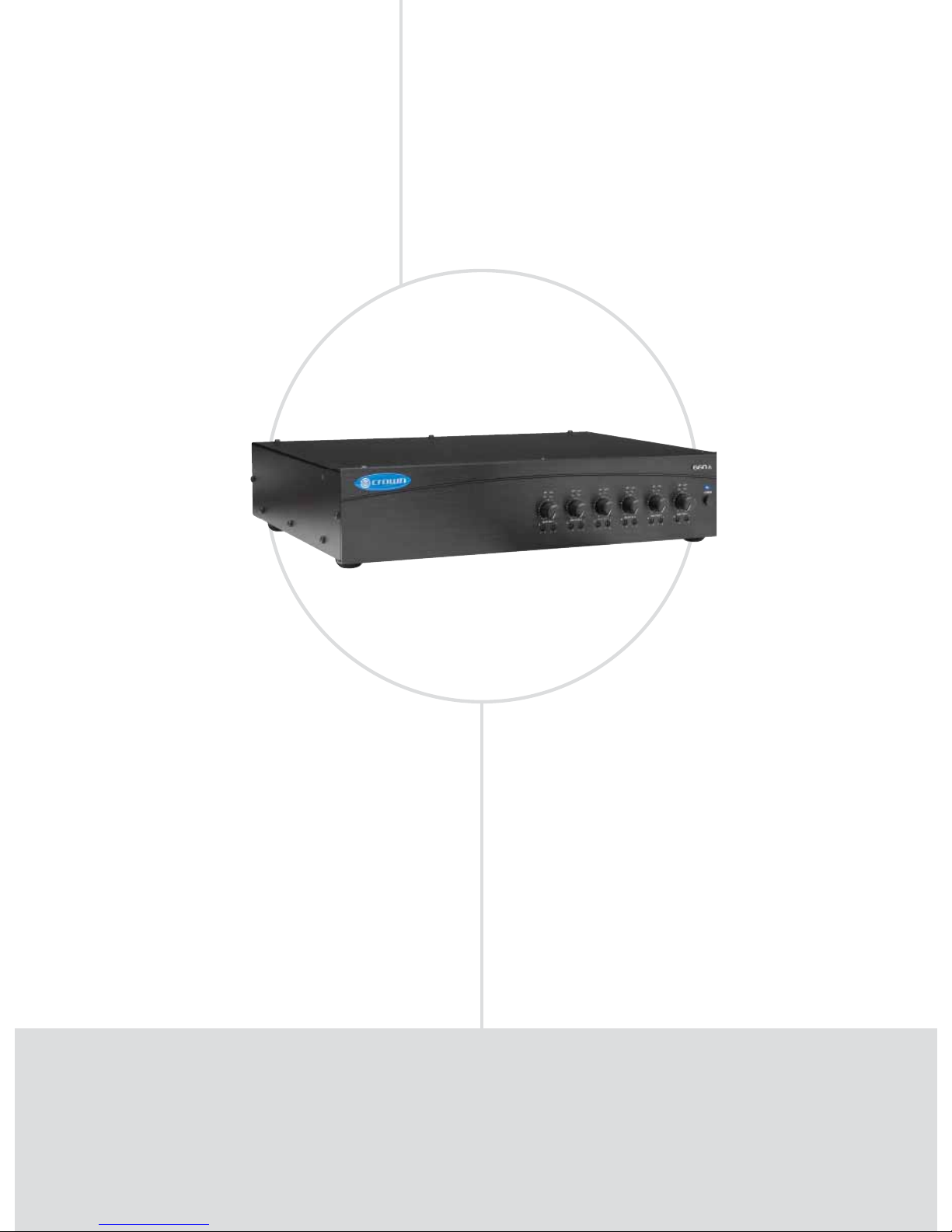
COMMERCIAL AUDIO AMPLIFIERS
660A
6-Channel
FEATURES
6 inputs; 6 amplifi er output channels.
Balanced Phoenix-type line inputs; touch-proof screw-terminal speaker
outputs.
Advanced protection system includes output current limiting,
DC protection, circuit breaker/fuse, and thermal protection.
Ideal for commercial and industrial use.
•
•
•
•
POWER OUTPUT*
Model 4-ohm 70V/100V Inputs System Zones
660A 60W 60W 6 Six-zone
*Minimum guaranteed power in watts at 1 kHz with 0.5% THD.
Page 23

COMMERCIAL AUDIO
• 23
www.crownaudio.com
T
he Crown® 660A is a very flexible, high-value six-channel amplifier for commercial and industrial
audio. It provides 4-ohm and constant-voltage outputs (70V and 100V) on channels 1 through 4,
and 4-ohm outputs on channels 5 and 6. The 660A is a part of Crown’s Commercial Audio Series, which
also includes mixers and mixer-amps. These low-cost units provide all necessary features in a simple
building-block format.
SPECIFICATIONS
Performance
Frequency Response (at 1 watt from 4-ohm tap):
70 Hz to 19 kHz ±1 dB.
Frequency Response (at line out): 20 Hz to 20 kHz
+/- 1 dB.
Power Bandwidth (at 4-ohm tap, 2 dB below
maximum 1 kHz power): 50 Hz to 20 kHz with
< 0.5% THD
Signal to Noise Ratio (ref. to rated power, master
volume at minimum): 85 dB.
DC Output Offset: < ±5 mV.
THD: Less than 0.5% at rated power at 1 kHz.
Input Sensitivity (for full output at maximum
gain): 800 mV.
Input Impedance (nominal): 100 kilohms.
Minimum Load Impedance:
100V output: 160 ohms
70V output: 80 ohms.
4-ohm output: 4/8 ohms
Crosstalk (all controls at “10”): –70 dB at 1kHz.
Line Output Level (nominal): 1V into 10 kilohms.
AC Line Voltage and Frequency Configurations
Available:
100V 50/60 Hz.
120V 60 Hz.
220V 50/60 Hz.
230V 50/60 Hz.
240V 50/60 Hz.
AC Voltage Tolerance: +10% –20%.
Operating Temperature/Humidity: 0° C to 40° C
at 95% relative humidity (non-condensing).
Storage Temperature: –20° C to 85° C.
Front Panel Controls and Indicators
Power Switch: Push-button on-off switch.
Power Indicator: Blue LED indicates power on.
Output Signal Presence Indicator: Green LED,
one for each output channel, illuminates when output signal level exceeds 100 mV (45 dB below full
power) from the 4-ohm tap.
Clip Indicators: Red LED, one per output channel.
Illuminates at threshold of audible distortion.
Master Volume Controls: One per output channel.
Detented potentiometer with knob.
Tone Controls: Bass and Treble non-detented
potentiometers on each channel. Bass ±10 dB at
100 Hz, Treble ±10 dB at 10 kHz.
Back Panel Controls and Connectors
Reset Switch: Resets the circuit breaker that pro-
tects the power supply. 220/230/240V units have a
fuse instead.
AC Power Inlet: Detachable IEC.
Amplifier Outputs Connectors: One per channel,
4-position terminal strip with COM (Common), 4
ohms, 70V and 100V terminals for channels 1-4
and one 4-position terminal strip (4 ohms, + and
– for each channel) for channels 5 and 6. Accepts
up to 10 AWG terminal forks. Non-touch cover
included.
Output VCA Connector: One for every two channels, 4-pin Phoenix-type connector for two VCA
control lines of +10 VDC and ground. Compatible
with Crown 1-VCAP and 4-VCAP modules.
Amp Input Connector: 3-pin Phoenix-type, highimpedance balanced, one per amplifier channel.
Cooling
Convection cooled.
Protection
Current Limit Protection: Included.
Thermal Limit Protection: Over-temperature
thermal cutout.
DC-Fault Load Protection: Included.
Included Accessories
Power cord.
Detachable rack ears.
Screws for rack ears.
Non-touch cover for output connectors.
Phoenix-type connectors.
Spade lugs.
Optional Accessories
1-VCAP remote volume control for one channel.
4-VCAP remote volume control for four channels.
Dimensions
Width (without rack ears): 17.3 in. (43.8 cm).
Width (with rack ears): EIA Standard 19 in. (48.3-
cm) W (EIA RS-310-B).
Height (front panel): 3.5 in. (8.9 cm).
Height (including feet): 4.1 in. (10.5 cm).
Depth (front panel to back panel): 12.2 in. (31.0
cm).
Depth (front of knobs to back of non-touch cover):
13.9 in. (35.2 cm).
Weight
Net Weight: 30.3 lb (13.7 kg).
Shipping Weight: 35.3 lb (16.0 kg).
Regulatory Certifications
Note: All measurements are related to 120VAC units 60
Hz in stereo mode with 8-ohm loads at 1 kHz at rated
power unless other otherwise specified. Specifications
for units supplied outside the U.S.A. may vary slightly
at different AC voltages and frequencies.
Page 24
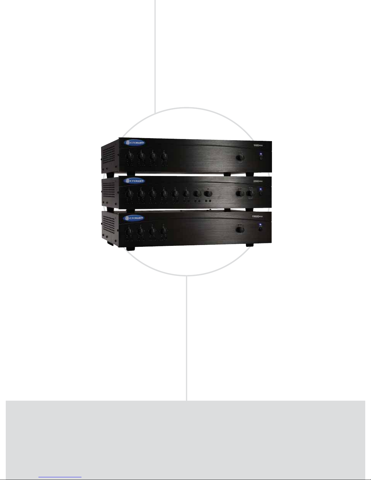
COMMERCIAL AUDIO MIXER-AMPLIFIERS
180MA, 280MA, 1160MA
Practical
FEATURES
4 to 8 inputs, 1 to 2 amplifi er output channels.
Ideal for commercial and industrial use.
Balanced Phoenix-type mic/line inputs; touch-proofed
screw-terminal speaker outputs.
Any input can be sent to any output.
Priority muting.
•
•
•
•
•
POWER OUTPUT*
Models 4-ohm 70V/100V Inputs System Zones
180MA 80W 80W 4 Single-zone
280MA 80W 80W 8 Two-zone
1160MA 160W 160W 4 Single-zone
*Minimum guaranteed power in watts at 1 kHz with 0.5% THD.
Page 25

COMMERCIAL AUDIO
• 25
www.crownaudio.com
C
rown’s Commercial Audio mixer/amplifiers deliver legendary Crown quality to the commercial audio
industry. These high-value mixer-amplifiers provide both 4-ohm and constant-voltage outputs (70V
and 100V) for use in a wide range of commercial applications including schools, hospitals, factories,
restaurant/retail, houses of worship, fitness facilities, A/V boardrooms, correctional facilities, and small
offices. Easily configured for a range of uses such as paging, background music, security, and evacuation instructions, Crown’s Commercial Audio units are the smart choice for commercial sound.
SPECIFICATIONS
Performance
Frequency Response: 70 Hz to 19 kHz ±1 dB at
line out.
Power Bandwidth: 50 Hz to 20 kHz with < 0.5%
THD at 2 dB below maximum 1 kHz power.
Signal to Noise Ratio: 85 dB, master volume at
minimum.
DC Output Offset: < ±5 mV.
THD: Less than 0.5% at rated power at 1 kHz.
Input Sensitivity (for full output at maximum
gain):
Balanced mic inputs: 3 mV.
Balanced line inputs: 800 mV.
RCA connectors: 400 mV.
Input Impedance:
Mic: 400 ohms.
Line: 100 k ohms.
RCA: 50 k ohms.
Crosstalk: –70 dB at 1kHz.
Line Output Level (nominal): 1V into 10 kilohms.
Phantom Power: 15 VDC.
AC Line Voltage and Frequency Configurations
Available:
100V 50/60 Hz
120V 60 Hz
220V 50/60 Hz
230V 50/60 Hz
240V 50/60 Hz.
Operating Temperature/Humidity: 0°C to 40°C at
95% relative humidity (non-condensing).
Storage Temperature: –20°C to 85°C.
Front Panel Controls and Indicators
Power Switch: Push-button on-off switch. The
power switch does not affect the 24V DC auxiliary
power input.
Input Volume Controls: Microphone/line, four in
180MA and 1160MA, eight in 280MA. Detented
pots with knobs.
Tone Controls: Bass and Treble non-detented
potentiometers on each input channel. Bass ±10 dB
at 100 Hz, Treble ±10 dB at 10 kHz.
Power Indicator: Blue LED indicates power on.
Input Signal Presence Indicator: Green LED, one
for each input channel, illuminates when input signal exceeds –24 dBu (line) or –70 dBu (mic).
Output Signal Presence Indicator: Green LED,
one for each output channel, illuminates when output signal level exceeds 100 mV.
Clip Indicators: Red LED, one per output channel.
Illuminates at threshold of audible distortion.
Output Volume Controls: One per output channel.
Detented potentiometer with knob.
Back Panel Controls and Connectors
Reset Switch: Resets the circuit breaker that pro-
tects the power supply. 220/230/240V units have a
fuse instead.
AC Power Inlet: Detachable IEC.
Auxiliary Power Input: 2-position terminal strip for
24 VDC (±10%) backup power. Accepts up to 14
AWG terminal forks.
Amplifier Outputs Connector: One per channel, 4position terminal strip with COM, 4 ohms, 70V and
100V terminals. Accepts up to 14 AWG terminal
forks. Non-touch cover included.
Output VCA Connector: 4-pin Phoenix-type connector for two VCA control lines of +10 VDC and
ground. Compatible with Crown 1-VCAP and 4VCAP modules.
Amp Config Switch: A DIP switch with two functions:
1. Assigns one of the inputs as the priority input
for each output, thereby temporarily muting the
remaining inputs. Muting is activated by contact
closure.
2. Global enable switch for phantom power. Does
not affect RCA inputs. Default position is off.
Priority Connector: 3-pin Phoenix-type connector
allows Input 1 or Input 5 (280MA only) to mute
other input signals by contact closure.
Input Routing Switch (280MA only): DIP switches
that assign each input signal to each output. One
switch per input.
Line Out Connector: One 3-pin balanced Phoenixtype connector per output channel. Post master,
pre-VCA, with level control. Level controlled by
master volume control.
Input Connectors: Mic/Line Connector, 3-pin
Phoenix-type, low-impedance balanced, one per
input channel. Dual RCA for stereo music signals,
unbalanced, summed together, two connectors
per input channel. Amp Input Connector, 3-pin
Phoenix-type, high-impedance balanced, one per
amplifier channel. Used to link an additional mixer
to the mixer-amplifier.
Mic/line Switch: Selects mic-level or line-level signals. One switch for each balanced input.
Link In/Out Switch: Slide switch, one per channel.
With the Link Switch IN, any signal applied to the
Amp Input connector will be mixed with the input
signal(s). With the Link Switch OUT, only the signal
from the Amp Input Connector will appear at the
amplifier output.
Cooling
Convection cooled.
Protection
Current Limit Protection; Thermal Limit Protection
(over-temperature thermal cutout); DC-Fault Load
Protection.
Included Accessories
Power cord
Detachable rack ears
Screws for rack ears
Non-touch cover for output connectors
Phoenix-type connectors
Spade lugs
Optional Accessories
1-VCAP remote volume control for one channel.
4-VCAP remote volume control for four channels.
Dimensions
Width (without rack ears): 17.3 in. (43.8 cm).
Width (with rack ears): EIA Standard 19 in. (48.3-
cm) W (EIA RS-310-B).
Height (front panel): 3.5 in. (8.9 cm).
Height (including feet): 4.1 in. (10.5 cm).
Depth (front panel to back panel): 12.2 in. (31.0
cm).
Depth (front of knobs to back of non-touch cover):
13.9 in. (35.2 cm).
Weight:
Net Weight:
180MA: 21.0 lbs. (9.5 kg).
280MA: 25.3 lbs. (11.5 kg)
1160MA: 25.3 lbs. (11.5 kg).
Shipping Weight:
180MA: 26.0 lbs. (11.8 kg).
280MA: 30.3 lbs. (13.7 kg).
1160MA: 30.3 lbs. (13.7 kg).
Regulatory Certifications
Note: All measurements are related to 120VAC units 60
Hz in stereo mode with 8-ohm loads at 1 kHz at rated
power unless other otherwise specified. Specifications
for units supplied outside the U.S.A. may vary slightly
at different AC voltages and frequencies.
Page 26
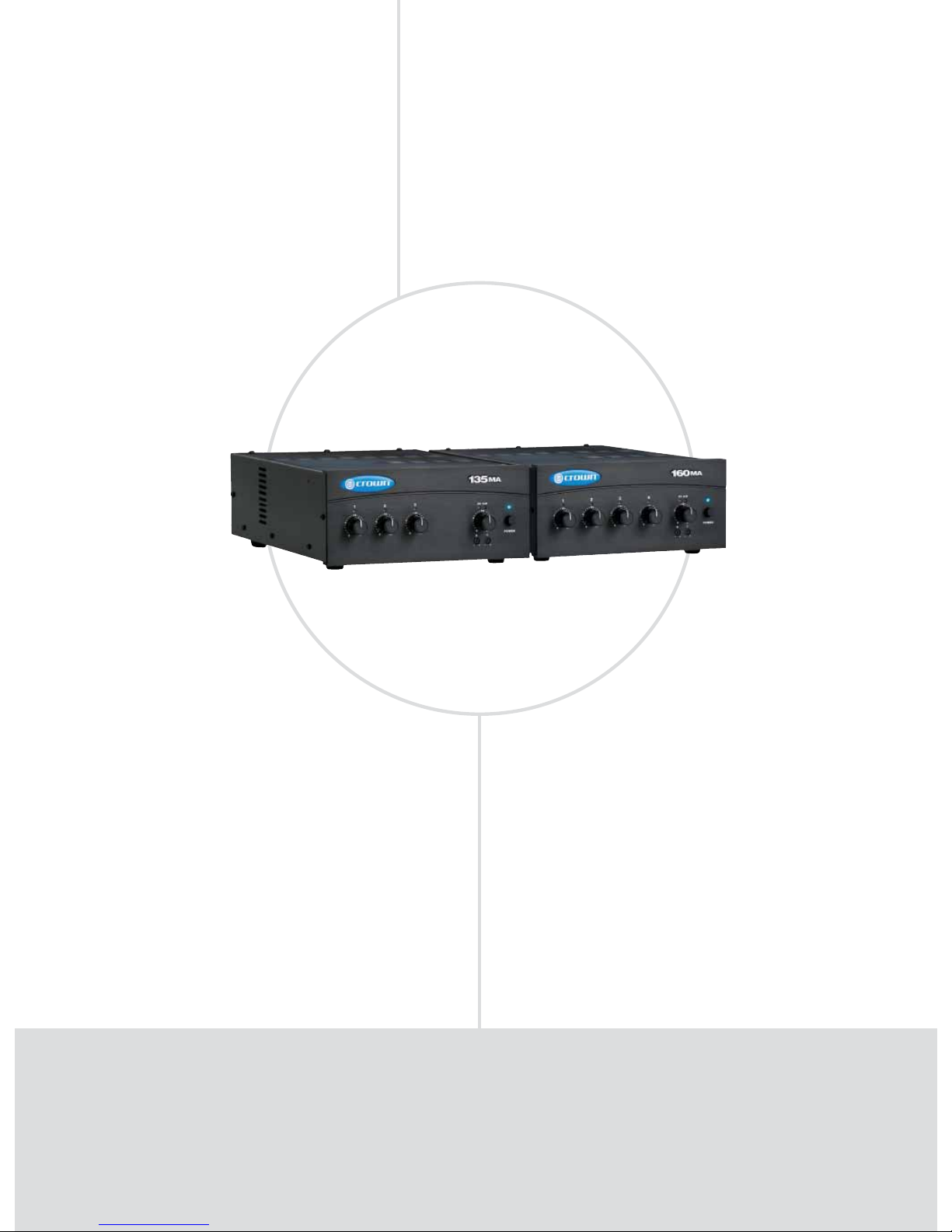
COMMERCIAL AUDIO MIXER-AMPLIFIERS
135MA, 160MA
Practical
FEATURES
3 inputs and one 35W amplifi er output channel in 135MA.
4 inputs and one 60W amplifi er output channel in 160MA.
Ideal for paging, background music, and music-on-hold.
Voice-activated priority muting (VOX).
Pre-amp outputs.
•
•
•
•
•
POWER OUTPUT*
Models 8-ohm 70V/100V Inputs System Zones
135MA 35W 35W 3 Single-zone
160MA 60W 60W 4 Single-zone
*Minimum guaranteed power in watts at 1 kHz with 0.5% THD.
NEW
NEW
Page 27

COMMERCIAL AUDIO
• 27
www.crownaudio.com
C
rown’s Commercial Audio mixer/amplifiers deliver legendary Crown quality to the commercial audio
industry. These high-value mixer-amplifiers provide both 8-ohm and constant-voltage outputs (70V
and 100V) for use in a wide range of commercial applications including schools, hospitals, factories,
restaurant/retail, houses of worship, fitness facilities, A/V boardrooms, correctional facilities, and small
offices. Easily configured for a range of uses such as paging, background music, security, and evacuation instructions, Crown’s Commercial Audio units are the smart choice for commercial sound.
SPECIFICATIONS
Performance
Frequency Response (at 1 watt from line out):
50 Hz to 20 kHz ± 1 dB.
19 Hz to 34 kHz +0, –3 dB.
Signal to Noise Ratio (ref. to rated power,
master volume at minimum):
Mic: > 58 dB.
Line: > 60 dB.
Telephone: > 60 dB.
Inputs 2 or 3 (and 4 in 160MA): > 78 dB.
THD + N: < 0.5% at rated power at 1 kHz.
< 0.1% at 5W at 1 kHz.
Input Sensitivity (for full output at maximum
gain):
Input 1: Mic 3mV, Line 800mV.
Input 2: 400mV.
Input 3: 400mV.
Input 4 (160MA only): 400mV.
Input Impedance (nominal):
Mic: 2.2 kilohms.
Line: 10 kilohms.
RCA: 10 kilohms.
Crosstalk: –82 dB at 1kHz (Ch. 1 line input
0.8V, Ch. 1 volume at minimum, other channel
volumes at maximum).
Line Output Level (nominal): 1V into 10
kilohms.
Phantom Power: 15 VDC.
AC Line Voltages Available:
Universal Power Supply. Line voltage tolerance
+15%, –20%.
Operating Temperature/Humidity: 0° C to 40°
C at 95% relative humidity (non-condensing).
Storage Temperature: –20° C to 85° C.
Front Panel Controls and Indicators
Power Switch: Pushbutton on-off switch.
Input Volume Controls: Four controls, one per
input. Detented potentiometers with knobs.
Tone Controls: Bass and Treble non-detented
recessed potentiometers under master output
volume control. Bass ±10 dB at 100 Hz, Treble
±10 dB at 10 kHz.
Power Indicator: Blue LED indicates power on.
Input Signal Presence Indicators: Green LED,
one above each channel's input attenuator,
illuminates when input signal exceeds –40 dBu.
Input Signal Clip Indicators: Green LED, one
above each channel's input attenuator, fl ashes
brightly at threshold of audible distortion.
Output Signal Presence Indicator: Green LED
above master output volume control illuminates
when any input signal exceeds –40 dBu.
Output Signal Clip Indicators: Red LED above
master output volume control fl ashes brightly at
threshold of audible distortion.
Master Output Volume Control: Detented
potentiometer with knob.
Back Panel Controls, Connectors and
Indicators
Fuse: Protects the power supply.
AC Power Inlet: Detachable IEC accepts US or
Euro style power cords.
Amplifi er Output Connector: 4-position termi-
nal barrier block with COM (Common), 8 ohms,
70V and 100V terminals. Accepts up to 10 AWG
terminal forks. Non-touch cover included.
Preamp Line Out Connector: 3-pin balanced
Phoenix-type for connection to external amplifi ers. Level independent of master volume
control.
Input Connector 1: 5-terminal Phoenix connector. 3 terminals for balanced signal, 2 terminals
for priority contact closure, which mutes other
channels when DIP switch 3 is on.
Input Connector 2: Unbalanced line-level RCAtype connectors.
Input Connector 3: Unbalanced line-level RCAtype connectors.
Input Connector 4 (160MA only): Unbalanced
line-level RCA-type connectors.
Telephone (MOH) Output Connector: 4-terminal
Phoenix connector (2 terminals for 1W output
to 8-ohm speaker, 2 terminals for 600-ohm
output to PBX music-on-hold port).
MOH Level Control: Trim pot adjusts level for
Music-On-Hold output from Telephone (MOH)
Output Connector.
Amp Confi guration DIP Switch: DIP switch
selection for multiple functions.
1. On: Sets CH1 to Mic Input. Off: Sets CH1 to
Line Input.
2. On: Sets CH1 to Normal mode (no priority).
3. On: CH1 priority contact closure mutes other
channels.
4. On: CH1 VOX mutes other channels by sensing signal through Input 1.
5. On: Routes CH1 to MOH output.
6. On: Routes CH2 to MOH output.
7. On: Routes CH3 to MOH output.
8. On: 15V phantom power.
VOX Threshold: Trim pot controls how loud
the voice on CH1 must be before muting other
channels. Can be set for no muting.
Cooling
Convection cooled.
Protection
Included protection mechanisms are current
limiting, over-temperature thermal cutout, and
DC-fault load protection. The unit is protected
aginst turn-on/turn-off thumps.
Included Accessories
Power cord
Non-touch cover for output connectors
Phoenix-type connectors
Spade lugs
Optional Accessories
Part no. IST 600-ohm Isolation Transformer for
Telephone Output or Input 1.
Part no. RM1 single rack mount kit for mounting a single MA unit in a rack.
Part no. RM2 double rack mount kit for mounting two MA units side-by-side in a rack.
Part no. S-Cover 10-pack of security knobs
Dimensions
Width: Half rack width (9.5 in. or 24.1 cm).
Height (front panel): 3.5 in. (8.9 cm).
Height (including feet): 4.1 in. (10.5 cm).
Depth (front panel to back panel): 12.2 in. (31.0
cm).
Depth (front of knobs to back panel): 13.9 in.
(35.2 cm).
Weight
Net Weight:
135MA: 8 lb 2 oz (3.7 kg).
160MA: 9 lb 7 oz (4.3 kg).
Shipping Weight:
135MA: 10 lb 16 oz (4.9 kg).
160MA: 12 lb 4 oz (5.6 kg).
Regulatory Certifications
Note: All measurements are related to 120VAC units 60
Hz in stereo mode with 8-ohm loads at 1 kHz at rated
power unless otherwise specified. Specifications for
units supplied outside the U.S.A. may vary slightly at
different AC voltages and frequencies.
Page 28
COMMERCIAL AUDIO MIXER-AMPLIFIERS
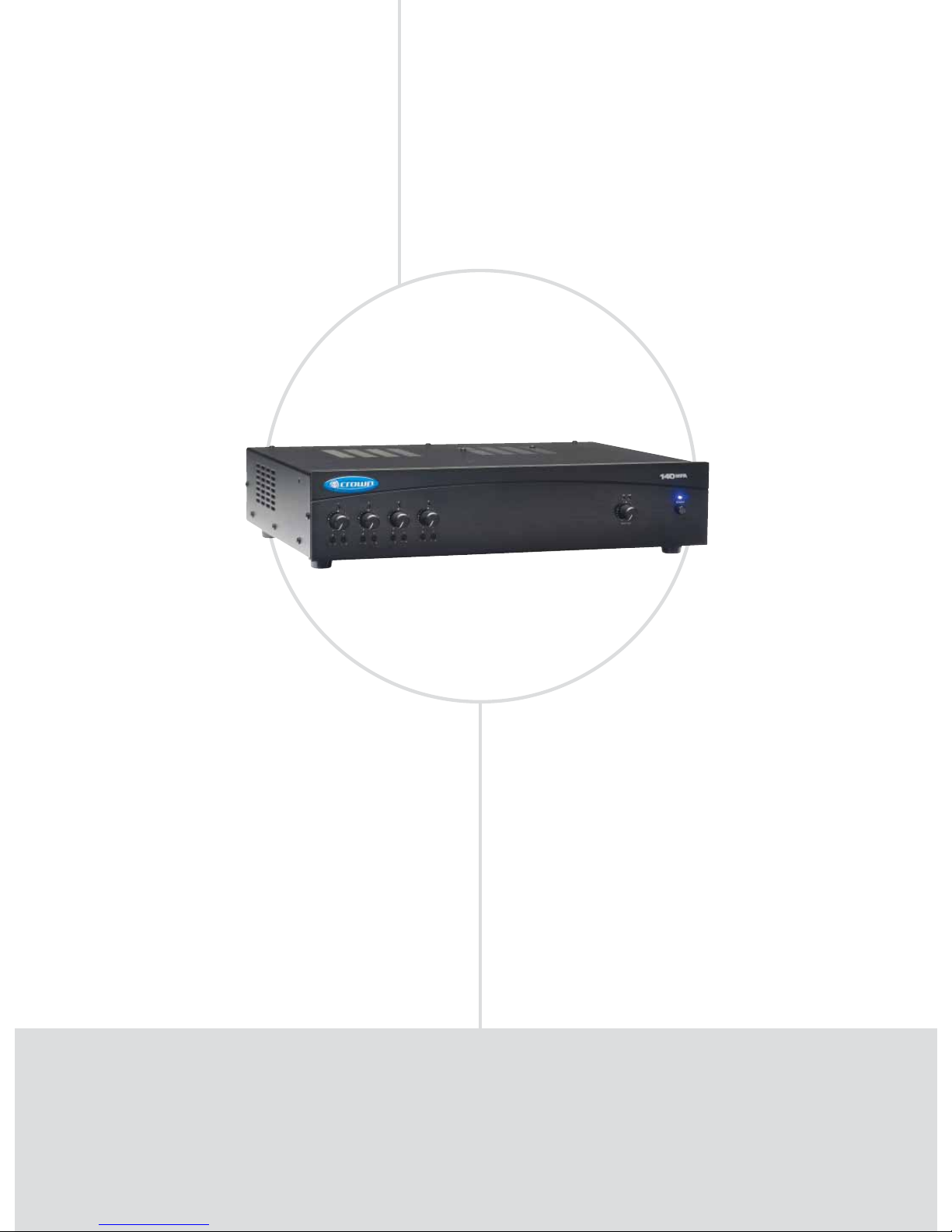
140MPA
Music & Paging
FEATURES
4 inputs (each with a volume control), one 40W amplifi er
output channel.
Ideal for paging, background music, and music-on-hold.
Balanced Phoenix-type mic/line inputs, telephone input,
dual RCA stereo music inputs, touch-proof screw-terminal
speaker outputs.
Priority ducking.
Independent bass and treble controls for each input.
•
•
•
•
•
POWER OUTPUT*
Model 4-ohm 25V/70V Inputs System Zones
140MPA 40W 40W 4 Single-zone
*Minimum guaranteed power in watts at 1 kHz with 0.5% THD.
Page 29

COMMERCIAL AUDIO
• 29
www.crownaudio.com
T
he Crown® 140MPA is a high-value mixer-amplifier for commercial audio. It provides 4-ohm and
constant-voltage outputs (25V and 70V). Typical uses are paging, background music, and musicon-hold. The unit provides 4 inputs (each with a volume control) and a 40W amplifier output. Other
features include priority ducking, phantom power, and capability for remote volume control. Multiple
units can be linked.
SPECIFICATIONS
Performance
Frequency Response (at 1 watt from 4-ohm tap):
50 Hz to 15 kHz ± 1 dB.
Frequency Response (at line out): 50 Hz to 15
kHz ± 1 dB.
Power Bandwidth (at 4-ohm tap, 2 dB below
maximum 1 kHz power): 50 Hz to 20 kHz with
< 0.5% THD.
Signal to Noise Ratio (ref. to rated power, master
volume at minimum): >90 dB.
DC Output Offset: < ±5 mV.
THD: < 0.5% at rated power at 1 kHz.
Input Sensitivity (for full output at maximum
gain):
Balanced mic inputs 3 mV.
Balanced line inputs 800 mV.
RCA connectors 400 mV.
Input Impedance (nominal):
Mic: 400 ohms.
Line: 100 kilohms.
RCA: 50 kilohms.
Crosstalk: –70 dB at 1kHz.
Line Output Level (nominal): 1V into 10 kilohms.
Phantom Power: 15 VDC.
AC Line Voltage and Frequency Configurations
Available: 120V/60Hz.
AC Voltage Tolerance: +15%, –20%.
Operating Temperature/Humidity: 0° C to 40° C
at 95% relative humidity (non-condensing).
Storage Temperature: –20° C to 85° C.
Front Panel Controls and Indicators
Power Switch: Pushbutton on-off switch.
Input Volume Controls: Four controls, one per
input. Detented potentiometers with knobs.
Tone Controls: Bass and Treble non-detented
recessed potentiometer on each input channel.
Bass ±10 dB at 100 Hz, Treble ±10 dB at 10 kHz.
Power Indicator: Blue LED indicates power on.
Input Signal Presence Indicator: Green LED, one
for each input channel, illuminates when input signal exceeds –40 dBu.
Output Signal Presence Indicator: Green LED illuminates when output signal level exceeds 100 mV
(45 dB below full power) from the 4-ohm tap.
Clip Indicator: Red LED on output illuminates at
threshold of audible distortion.
Master Output Volume Control: Detented potentiometer with knob.
Back Panel Controls, Connectors and
Indicators
Reset Switch: Resets the circuit breaker that pro-
tects the power supply.
AC Power Inlet: Detachable IEC.
Amplifier Output Connector: 4-position terminal
strip with COM (Common), 4 ohms, 25V and 70V
terminals. Accepts up to 10 AWG terminal forks.
Non-touch cover included.
Output VCA Connector: 4-pin Phoenix-type connector for two VCA control lines of +10 VDC and
ground. Compatible with Crown 1-VCAP module.
Priority Connector: 3-pin Phoenix-type connector
for push-to-talk mic contact closure.
Preamp Line Out Connector: 3-pin balanced
Phoenix-type connector. Post master, pre-VCA.
Level controlled by master volume control.
MOH 1V Level Control: Trim pot adjusts level for
Music-On-Hold 1V output.
MOH 1W Level Control: Trim pot adjusts level for
Music-On-Hold 1W output.
MOH SPI Indicator: Flashes when MOH signal is
present.
MOH 1V Phoenix Connector: 3-pin Phoenix
connector for 1V, 600-ohm transformer-isolated
output.
MOH 1W Phoenix Connector: 3-pin Phoenix connector for 1W output.
MOH 1V RCA Connector: Two mono RCA connectors for 1V output (in parallel with 600-ohm connections so they are isolated).
Balanced Input Connector: Detachable 3-pin
Phoenix style connector for balanced line-level signals, one each for input channels 2-4.
Balanced Input Connector: Detachable 3-pin
Phoenix style connector for balanced mic-level linelevel signals, for input channel 1.
Tel Connector: Transformer-isolated 600-ohm
input, summed into Input 1 for paging from a telephone system.
Dual RCA Input Connector: For stereo music
signals, unbalanced, summed together, two connectors per input channel.
Amp Input Connector: 3-pin Phoenix-type, high
impedance balanced. Used to link an additional
mixer to the mixer-amplifier. Can be used to connect an external processor.
Mic/line Switch: Selects mic-level or line-level
signal for Input 1.
Phantom Power Switch: Turns phantom power on
or off for Input 1.
VOX Threshold: Trim pot controls how loud the
voice must be before ducking occurs. Can be set
for no ducking.
Link In/Out Switch: Slide switch. When set to IN,
any signal applied to the Amp Input connector will
be mixed with the input signal(s). When set to OUT,
only the signal from the Amp Input Connector will
appear at the amplifier output.
Priority Connector: 3-pin Phoenix-type connector
for push-to-talk mic contact closure. Input 1 is
the priority input for the amplified output, so Input
1 ducks the other inputs. Threshold of activation
depends on input voltage. Ducking does not affect
MOH outputs.
Active Indicator: Illuminates when VOX ducking
is active.
Cooling
Convection cooled.
Protection
Current Limit Protection: Included.
Thermal Limit Protection: Over-temperature
thermal cutout.
DC-Fault Load Protection: Included.
Turn On/Turn Off: No thumps or pops.
Included Accessories
Power cord.
Detachable rack ears.
Screws for rack ears.
Non-touch cover for output connectors.
Phoenix-type connectors.
Spade lugs.
Optional Accessories
1-VCAP remote volume control.
Dimensions
Width (without rack ears): 17.3 in. (43.8 cm).
Width (with rack ears): EIA Standard 19 in. (48.3-
cm) W (EIA RS-310-B).
Height (front panel): 3.5 in. (8.9 cm).
Height (including feet): 4.1 in. (10.5 cm).
Depth (front panel to back panel): 12.2 in. (31.0
cm).
Depth (front of knobs to back of non-touch cover):
13.9 in. (35.2 cm).
Weight
Net Weight: 17 lb (7.7 kg).
Shipping Weight: 22 lb (9.98 kg).
Regulatory Certifications
Page 30
XM Enabled
FEATURES
Programmable XM tuner with XM channel data display.
Independent bass and treble controls for each input.
Balanced Phoenix-type mic/line inputs; touch-proof screw-
terminal speaker outputs.
Priority ducking, Music-On-Hold (MOH) outputs.
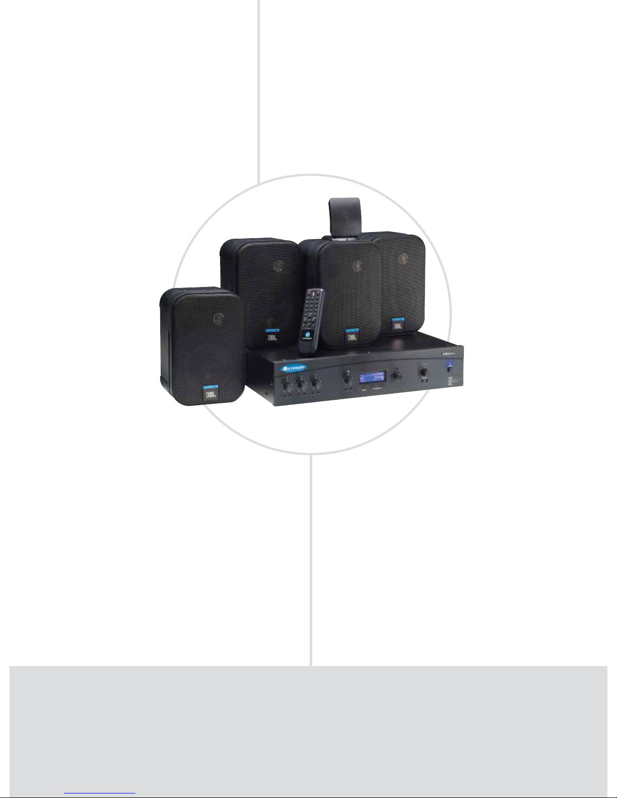
180 MAx Pack includes four JBL Control 1ST 2-way speak-
ers with 70V transformer and mounting brackets, remote
control and XM antenna.
•
•
•
•
•
POWER OUTPUT*
Model 4-ohm 25V/70V Inputs System Zones
180MAx 80W 80W 4 Single-zone
*Minimum guaranteed power in watts at 1 kHz with 0.5% THD.
COMMERCIAL AUDIO XM TUNER-MIXER-AMPLIFIERS
180MAx Pack (180MAx tuner-mixer-amplifier also available separately)
Page 31

COMMERCIAL AUDIO
• 31
www.crownaudio.com
T
he Crown® 180MAx Pack is the first tuner-mixer-amplifier and loudspeaker system designed for
commercial use. It is designed for easy installation. Applications include restaurants, retail stores,
coffee shops and other commercial establishments. The system includes the Crown 180MAx tunermixer-amplifier (also available separately), four JBL
®
Control® 1ST 2-way loudspeakers with built-in
70V transformers, XM antenna and a wireless remote control. Built into the 180MAx is an XM Radio
tuner that receives satellite radio stations with digital sound quality. The unit also accepts signals from
line, telephone, or microphone (phantom power included). Other features include bass and treble
controls, and priority ducking.
SPECIFICATIONS
Performance
Frequency Response (at 1 watt from 4-ohm tap):
70 Hz to 19 kHz ±1 dB.
Frequency Response (at line out): 20 Hz to 20 kHz
±1 dB.
Power Bandwidth (at 4-ohm tap, 2 dB below maxi-
mum 1 kHz power): 50 Hz to 20 kHz with
< 0.5% THD
Signal to Noise Ratio (ref. to rated power, master
volume at minimum): 85 dB.
DC Output Offset: < ±5 mV.
THD: Less than 0.5% at rated power at 1 kHz.
Input Sensitivity (for full output at maximum gain)
Balanced mic inputs: 3 mV.
Balanced line inputs: 800 mV.
RCA connectors: 400 mV.
Isolated telephone input: 75 mV.
Input Impedance (nominal):
Mic: 400 ohms.
Line: 100 kilohms.
RCA: 50 kilohms.
Telephone: 600 ohms.
Crosstalk: –70 dB at 1kHz.
Line Output Level (nominal): 1V into 10 kilohms.
Phantom Power: 15 VDC.
AC Line Voltage and Frequency Configurations
Available: 120V, 60 Hz.
AC Voltage Tolerance: +10%, –20%.
Operating Temperature/Humidity: 0° C to 40° C
at 95% relative humidity (non-condensing).
Storage Temperature: –20° C to 85° C.
Front Panel Controls and Indicators
Power Switch: Pushbutton on-off switch.
Input Volume Controls: Four detented potentiom-
eters with knobs.
Input 1: Microphone/line (switchable)/telephone.
Inputs 2 and 3: Line.
Input 4: XM radio.
Tone Controls: Bass and Treble non-detented
recessed potentiometers on each input channel.
Bass ±10 dB at 100 Hz, Treble ±10 dB at 10 kHz.
XM Tuner Menu Button: Selects Direct, Preset, or
Category mode.
XM Tuner Category Buttons: Scrolls through categories (rock, classical, news, country, etc).
XM Tuner Scroll Knob: Lets you scroll through
channels and select them.
XM Tuner Display: LCD screen displays XM channel data (channel number, channel name, artist
name, song title), 16 station presets and signal
strength.
Power Indicator: Blue LED indicates power on.
Input Signal Presence Indicator: Green LED, one
for each input channel, illuminates when input signal exceeds –24 dBu (line) or –70 dBu (mic).
Output Signal Presence Indicator: Green LED,
illuminates when output signal level exceeds 100
mV (45 dB below full power) from the 4-ohm tap.
Clip Indicator: Red LED on output illuminates at
threshold of audible distortion.
Output Volume Control: Detented potentiometer
with knob.
Back Panel Controls, Connectors and Indicators
Reset Switch: Resets the circuit breaker that pro-
tects the power supply.
MOH 1V Level Control: Trim pot adjusts level for
Music-On-Hold 1V output.
MOH 1W Level Control: Trim pot adjusts level for
Music-On-Hold 1W output.
MOH Signal Presence Indicator: Flashes when
MOH signal is present.
MOH Source Switch: Switches between Input 3 or
XM, and routes the source to MOH 1V Line Out and
MOH 1W connectors.
MOH 1W Select Switch: Feeds 1W MOH signal
either to amplifier output or internal speaker.
MOH 1V Line Output RCA Connectors: Two RCA
connectors (mono) for 1-volt output (in parallel
with 600-ohm connectors, so they are isolated).
MOH 1W Line Output Connector: 3-pin Phoenix
connector provides Music-On-Hold signal of
approximately 1 watt.
MOH 1V Line Output Phoenix Connector: 3-pin
Phoenix connector, 600-ohm transformer-isolated
output, provides Music-On-Hold signal of approximately 1 volt.
Phantom Power Switch: Turns phantom power on
or off for Input 1.
Mic/line Switch: Selects mic-level or line-level
signal for Input 1.
Link In/Out Switch: Slide switch. When set to IN,
any signal applied to the Amp Input connector will
be mixed with the input signal(s); when set to OUT,
only the signal from the Amp Input Connector will
appear at the amplifier output.
Amplifier Output Connectors: 4-position terminal
strip with COM (Common), 4 ohms, 25V and 70V
terminals. Accepts up to 10 AWG crimp-on terminal
forks. Non-touch cover included.
XM Radio Stereo Line Out Connector: Dual RCA
jacks for stereo music out from XM Radio tuner.
Preamp Line Out Connector: 3-pin balanced
Phoenix-type connector. Post master, pre-VCA.
Level controlled by master volume control.
Output VCA Connector: 3-pin Phoenix-type connector for two VCA control lines of +10 VDC and
ground. Compatible with Crown 1-VCAP module.
Priority Connector: 3-pin Phoenix-type connector
for push-to-talk mic switch. Contact closure activates ducking. Ducking does not affect Music-OnHold outputs or XM stereo line out.
Active Indicator: LED illuminates when ducking
is active.
VOX Threshold: Trim pot adjusts how loud the
voice must be before ducking occurs. Can be set
for no ducking.
Priority Release Control: Trim pot adjusts release
time of VOX ducking.
Mic/Line Input Connector (Input 1 only): 3-pin
Phoenix-type, balanced.
Line Input Connectors (Inputs 2 and 3 only): 3-pin
Phoenix-type, balanced.
Dual RCA Input Connector: For stereo music
signals, unbalanced, summed together, two connectors per input for inputs 1, 2 and 3.
TEL Input Connector: Transformer-isolated 600ohm input, summed into Input 1 for paging from a
telephone system.
Amp Input Connector: 3-pin Phoenix-type, highimpedance balanced. Used to link an additional
mixer to the mixer-amplifier. Can be used to connect an external processor.
AC Power Inlet: Detachable IEC.
XM Radio Antenna Input: Connects to the XM
antenna cable.
Cooling and Protection
Convection cooled, current limiting, thermal limiting, DC Fault.
Included Accessories
Power cord, detachable rack ears, screws for
rack ears, non-touch cover for output connectors,
Phoenix-type connectors. spade lugs, XM antenna,
remote control.
Optional Accessories
1-VCAP remote volume control.
Dimensions
Width (without rack ears): 17.3 in. (43.8 cm).
Width (with rack ears): EIA Standard 19-in. (48.3cm) W (EIA RS-310-B).
Height (front panel): 3.5 in. (8.9 cm).
Height (including feet): 4.1 in. (10.5 cm).
Depth (front panel to back panel): 12.2 in. (31.0
cm).
Depth (front of knobs to back of non-touch
cover): 13.9 in. (35.2 cm).
Weight
Net Weight: 20 lb (9.07 kg).
Shipping Weight (complete system): 55 lb (24.8
kg).
Regulatory Certifications
Note: All measurements are related to 120VAC units 60
Hz in stereo mode with 4-ohm loads at 1 kHz at rated
power unless other otherwise specified. Specifications
for units supplied outside the U.S.A. may vary slightly at
different AC voltages and frequencies.
Page 32
COMMERCIAL AUDIO
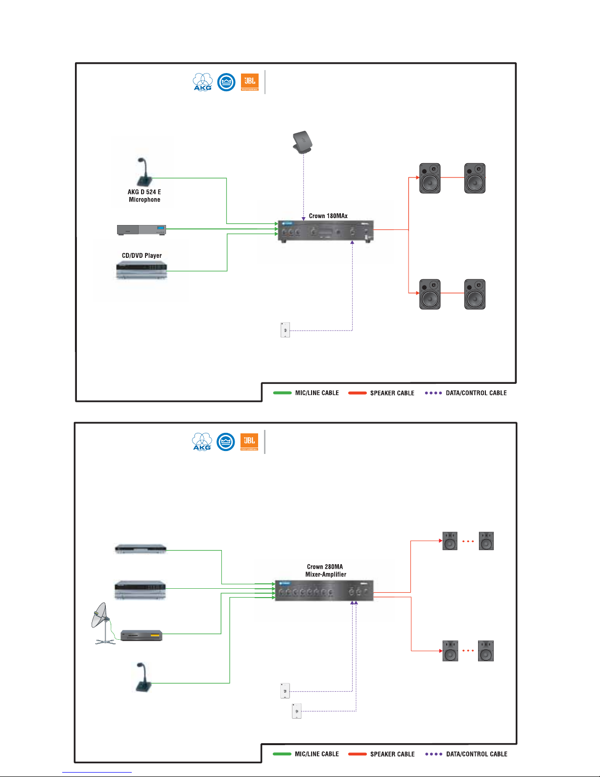
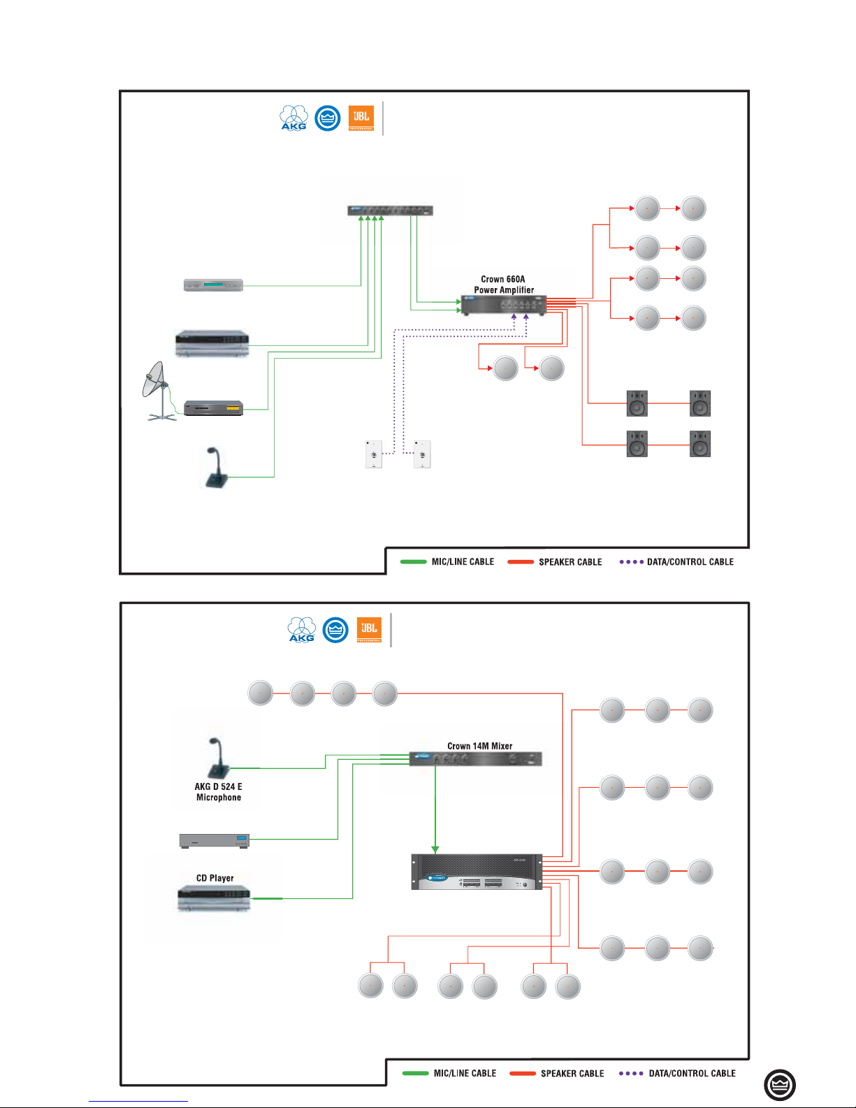
Product Applications
Small Pub
Using 180MAx PACK
AKG D 524 E
Microphone
CD/DVD Player
Crown 1-VCAP
Crown 180MAx
JBL Control 1ST
Cable TV Box
Wall Volume Control
XM Antenna
Small Restaurant
AKG D 524 ST-S
Microphone
Harman Kardon
FL 8385 CD Player
Satellite Receiver
JBL Control 25T
JBL Control 28T-60
Harman Kardon
DVD-31 Player
Zone 1
Zone 2
Crown 1-VCAPs
Zone 1
Zone 2
Crown 280MA
Mixer-Amplifier
Page 33
• 33
COMMERCIAL AUDIO
Product Applications
Medium Retail Store
AKG D 524 ST-S
Microphone
Harman Kardon
FL 8385 CD Player
Satellite Receiver
1-VCAP
JBL Control 24CT
Crown 28M Mixer
JBL Control 24CT
JBL Control 25AV
Crown 660A
Power Amplifier
Music Service
JBL Control 19CS
Branded Apparel Store
AKG D 524 E
Microphone
CD Player
Crown 14M Mixer
Music Service
Crown CTs 8200
Power Amplifier
JBL Control 26CT (Ceiling Mount)
JBL Control 24CT (Ceiling Mount)
Restrooms - Hallways
JBL Control 19CS Subwoofers (Ceiling Mount)
Page 34
Page 35
XTi Series
XLS Series
PORTABLE PA
Page 36
AMPLIFIERS PORTABLE PA
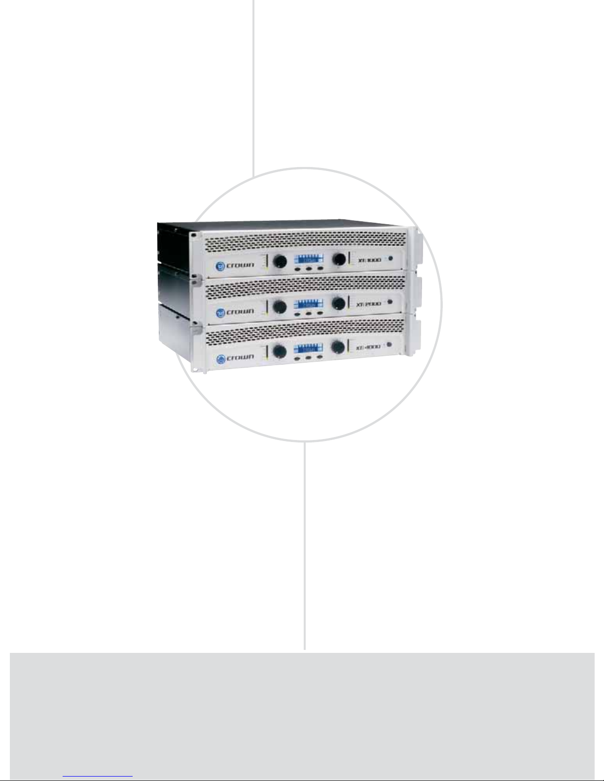
XTi Series: World Class
XTi 1000, XTi 2000, XTi 4000
World-Class
FEATURES
Computer connectivity via USB allows fast setup and confi guration
with HiQnet™.
Integrated speaker presets with LCD front panel display.
Extremely versatile, handling a wide range of speaker impedances
and outputs.
Switch-mode universal power supply.
Speaker presets for crossover frequencies, EQ, limiting, and delay.
All products fi ll 2U rack spaces and weigh under 19 pounds; weight
sets a new standard in lightweight amps.
Speakon® and binding post outputs, XLR inputs and loop-thrus.
Comprehensive LED status per channel.
•
•
•
•
•
•
•
•
POWER OUTPUT
2-ohm Dual 4-ohm Dual 8-ohm Dual 4-ohm 8-ohm
Model (per channel) (per channel) (per channel) Bridge Bridge
XTi 1000 700W** 500W* 275W* 1,400W** 1,000W*
XTi 2000 1,000W** 800W* 475W* 2,000W** 1,600W*
XTi 4000 1,600W** 1,200W* 650W* 3,200W** 2,400W*
*1 kHz power with 0.5% THD. ** With 1% THD.
Page 37

PORTABLE PA
• 37
www.crownaudio.com
SPECIFICATIONS
Performance
Voltage Gain at 1kHz, 8 ohm rated output:
XTi 1000: 30.5 dB.
XTi 2000: 32.9 dB.
XTi 4000: 34.2 dB.
Frequency Response: +0/–1 dB from 20 Hz to 20
kHz at 1 watt into 4 ohms.
Load Impedance: Safe with all types of loads.
Rated for 2 to 8 ohms in Stereo mode, 4 to 16
ohms in Bridge-Mono mode.
Sensitivity: 1.4V.
Signal to Noise Ratio (below rated 1 kHz power at
8 ohms): 100 dB (A weighted).
Damping Factor: Better than 500 from 20 Hz to
400 Hz.
Crosstalk: > 70 dB below rated power, 20 Hz to
1 kHz.
Input Stage: Input is electronically balanced and
employs precision 1% resistors.
Input Impedance (nominal): 20 k ohms, balanced;
10 k ohms, unbalanced.
Maximum Input Signal: +22 dBu typical.
AC Line Voltage and Frequency Configurations
Available: 100V, 120V, 220-240V, 50/60 Hz.
AC Line Current:
XTi 1000: 6.5A.
XTi 2000: 6.9A.
XTi 4000: 8.0A.
At Idle: Draws no more than 90 watts.
Operating Temperature: 0° C to 40° C at 95%
relative humidity (non-condensing).
DSP Section
Input EQ: 6 parametric fi lters per channel with
adjustable Q, ±15 dB boost/cut. Also adjustable
high and low shelving fi lters. This 8-fi lter EQ
section can be bypassed.
Crossover Filters: Highpass and lowpass
per channel. Butterworth 6/12/18/24 dB per
octave. Linkwitz-Riley 24/48 dB per octave. Also
includes ±15 dB bandpass gain and polarity
control.
Delay: For signal alignment of driver; 50 mS
total delay.
Subharmonic Synthesizer: Takes the low-frequency content of the input signal and “synthesizes” a new signal that is the same as the input
signal but one octave lower. The new synthesized signal is then mixed with the original signal
to create the effect.
Output Limiter: Prevents clipping.
Presets: 20 presets, 19 of which are user-
defi nable.
Front Panel Controls and Indicators
Level: Detented rotary level control, one per
channel.
Power Switch: On/off switch applies AC power to
the amplifier.
Sel/Prev/Next Buttons: Three buttons near the
LCD screen are used to access menu items and
front panel lockout.
LCD Screen: Backlit liquid crystal display shows
speaker presets.
Signal Indicator: Green LED, one per channel, illuminates when a very low-level signal is present at
input. May be used for troubleshooting cable runs.
–10 Indicator: Green LED flashes when output
signal exceeds –10 dB below clip.
–20 Indicator: Green LED flashes when output
signal level exceeds –20 dB below clip.
Ready Indicator: Green LED, one per channel,
illuminates when the amplifier is ready to produce
audio.
Clip Indicator: Red LED, one per channel, turns on
at the threshold of audible distortion.
Temp Indicator: Red LED, one per channel, illuminates under excessive temperature conditions.
Power Indicator: Blue LED illuminates when the
amplifier has been turned on and has power.
Back Panel Controls and Connectors
AC Line Connector: NEMA 5-15P (15A).
Input Connector: XLR, one per channel.
Link/Out Connector: Loop-thru signal from input
connector for linking to another amplifier, one per
channel.
Output Connectors: Two Neutrik
®
Speakon®
NL4MP (mates with NL4FC) output connectors.
Channel-1 Speakon® is wired with Ch. 1 and Ch.
2 outputs for use with optional single 4-conductor
cable. Two binding post outputs (in parallel with
Speakon
®
connectors).
HiQnet USB Connector: Type B, connects to a
HiQnet network.
Protection
XTi-Series amplifiers are protected against shorted,
open or mismatched loads; overloaded power
supplies; excessive temperature; chain destruction
phenomena; excessive output current, input overload damage; and high-frequency blowups. They
also protect loudspeakers from input/output DC,
large or dangerous DC offsets and turn-on/turn-off
transients.
Construction
Chassis: Steel.
Cooling
Proportional speed fan with front-to-rear airflow.
Dimensions
EIA Standard 19-in. (48.3-cm) rack mount width
(EIA RS-310-B), 3.5 in. (8.9 cm) high and 12.25 in.
(31.11 cm) deep behind mounting surface.
Weight
Net Weight: 18.5 lb (8.4 kg).
Shipping Weight: 21.5 lb (9.8 kg).
Regulatory Certifications
Other Applications
Note: Specifications apply to units in Stereo mode with
8-ohm loads and rated input sensitivity unless otherwise specified.
T
he XTi Series of Crown® amplifiers are professional tools designed and built for portable PA appli-
cations. The series includes three models which are identical except for output power: XTi 1000,
2000 and 4000. All are rugged and lightweight, and offer unmatched value in their class. XTi-Series
amplifiers feature an LCD screen with speaker presets for crossover frequencies, EQ, limiting, delay,
and a subharmonic synthesizer. Other features include a switch-mode universal power supply, useful
function indicators, proportional-speed fan-assisted cooling, XLR inputs, Speakon® and binding-post
outputs, short-circuit protection and more.
Page 38
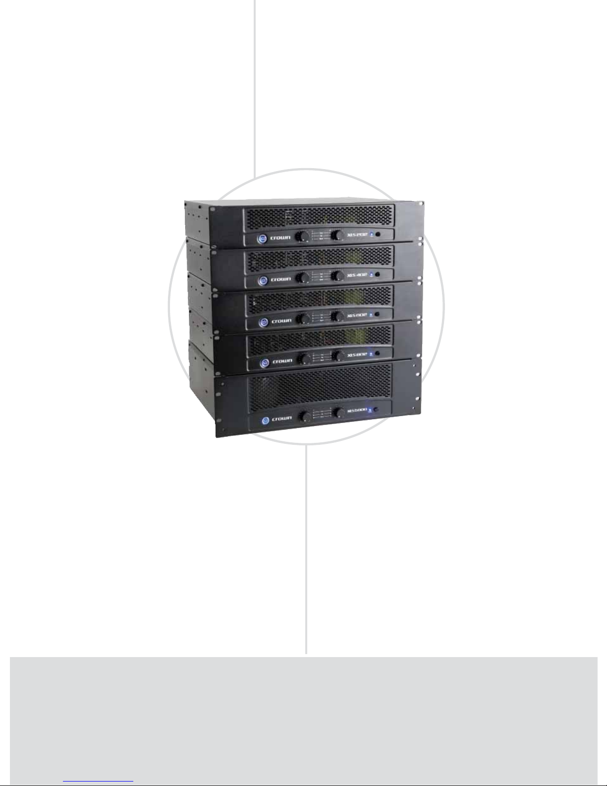
AMPLIFIERS PORTABLE PA
XLS Series: Affordable and Reliable
Evolution
FEATURES
Housed in a rugged, all-steel 2U chassis (3U for the XLS 5000).
Effi cient forced-air fan prevents excessive thermal buildup.
Electronically balanced XLR inputs; touchproof binding post and
Speakon outputs.
Precision detented level controls, power switch, and four LEDs,
which indicate clip for each channel, power and fault conditions.
•
•
•
•
POWER OUTPUT*
2-ohm Dual 4-ohm Dual 8-ohm Dual 8-ohm 4-ohm
Models (per channel) (per channel) (per channel) Bridge Bridge
XLS 202 -- 300W 200W 600W -XLS 402 -- 450W 300W 900W -XLS 602 -- 600W 380W 1,200W -XLS 802 -- 800W 500W 1,600W -XLS 5000 2,500W‡ 1,800W** 1,100W** 3,600W** 5,000W‡
*Maximum average power in watts at 0.5% THD, 1 kHz. **With 0.1% THD ‡With 1% THD
XLS 202, XLS 402, XLS 602, XLS 802, XLS 5000
NEW
Page 39

PORTABLE PA
• 39
www.crownaudio.com
SPECIFICATIONS
Performance
Sensitivity (volts RMS) for full rated power at 4
ohms: 1.25 V.
Frequency Response (at 1 watt) 22 Hz to
20 kHz: +0 dB, –1 dB.
Signal-to-Noise Ratio (20 Hz to 20 kHz, inputs
terminated)
A-weighted, below rated power: > 100 dB.
No weighting, below rated power: > 95 dB.
Total Harmonic Distortion (THD): < 0.5%.
Intermodulation Distortion (IMD):
(60 Hz and 7 kHz at 4:1) from full rated output to
–40 dB: < 0.3%.
Damping Factor (8 ohm) 10 Hz to 400 Hz: > 200.
Crosstalk (below rated power)
at 1 kHz: –75 dB.
at 20 kHz: –50 dB.
Input Impedance (nominal): 20 kilohms balanced,
10 kilohms unbalanced.
Load Impedance:
XLS 202, 402, 602, 802: 4 to 8 ohms per channel in Stereo, 8 ohms in Bridge Mono.
XLS 5000: 2 to 8 ohms per channel in Stereo, 4
to 8 ohms in Bridge Mono.
AC Line Voltage and Frequency Configurations
Available (±10%): 120V-60 Hz, 100V-50/60 Hz,
220V-50 Hz, and 230-240V.
Front Panel Controls and Indicators
Level: Two front-panel rotary level controls, one
for each channel.
Power: On when in the IN position.
Signal Presence Indicators: Two green LEDs, one
for each channel, illuminate when the channel’s
input signal exceeds –40 dBu.
Clip Indicators: Two red LEDs, one for each channel, illuminate when the channel’s output is being
overdriven.
Power Indicator: Blue LED indicates amplifier
has been turned on and AC power is available.
Fault Indicator: Two red LEDs, one for each channel, illuminate when amplifier is in protect mode.
Also illuminates briefly during normal power-up
when amplifier is first switched on.
Back Panel Connectors and Controls
Input Connectors: One per channel; three-pin
female XLR input connectors.
Output Connectors: Two 4-Pole Speakon® Output
Connectors accept 2-pole or 4-pole Speakon connectors. The top Speakon connector is wired for
both channels so it can be used for bridge-mono
wiring or for stereo wiring of two speakers to a
single Speakon connector.
One pair of binding posts per channel; accepts
banana plugs or bare wire. (European models do
not accept banana plugs.)
Circuit Breaker: Provides overload protection.
Mode Switch: Selects Dual or Bridge-Mono mode.
Protection
XLS Series amplifiers provide extensive protection
and diagnostic capabilities, including output current
limiting, DC protection, circuit breaker, and thermal
protection.
Cooling
Internal heat sinks with forced-air cooling for rapid,
uniform heat dissipation. Flow-through ventilation
from front to back.
Dimensions (XLS 202, 402, 602, 802)
EIA Standard 19-inch (48.3-cm) rack mount width
(EIA RS-310-B), 3.5-inch (8.9-cm) height and 15.2inch (38.6-cm) depth.
Dimensions (XLS 5000)
EIA Standard 19-inch (48.3-cm) rack mount width
(EIA RS-310-B), 5.25-inch (13.3-cm) height and
15.5-inch (39.5-cm) depth.
Weight
Net Weight:
XLS 202: 23.0 lb (10.4 kg).
XLS 402: 25.7 lb (11.7 kg).
XLS 602: 29.0 lb (13.2 kg).
XLS 802: 35.5 lb (16.1 kg).
XLS 5000: 62.0 lb* (27.7 kg)*.
Shipping Weight:
XLS 202: 28.0 lb (12.7 kg).
XLS 402: 30.7 lb (13.9 kg).
XLS 602: 34.0 lb (15.4 kg).
XLS 802: 40.5 lb (18.4 kg).
XLS 5000: 62.0 lb (27.7 kg).
Regulatory Certifications
Other Applications
Note: Specifications apply to units in Stereo mode with
8-ohm loads and rated input sensitivity unless otherwise specified.
T
he XLS Series of power amplifiers from Crown represents a new era in affordable, quality power
amplification. The line consists of five models in a uniform, rugged 2U chassis (3U for the XLS
5000), incorporating the best of tried-and-true design principles and innovative features.
except
XLS 5000
XLS 5000
only
except
XLS 5000
except
XLS 5000
Page 40
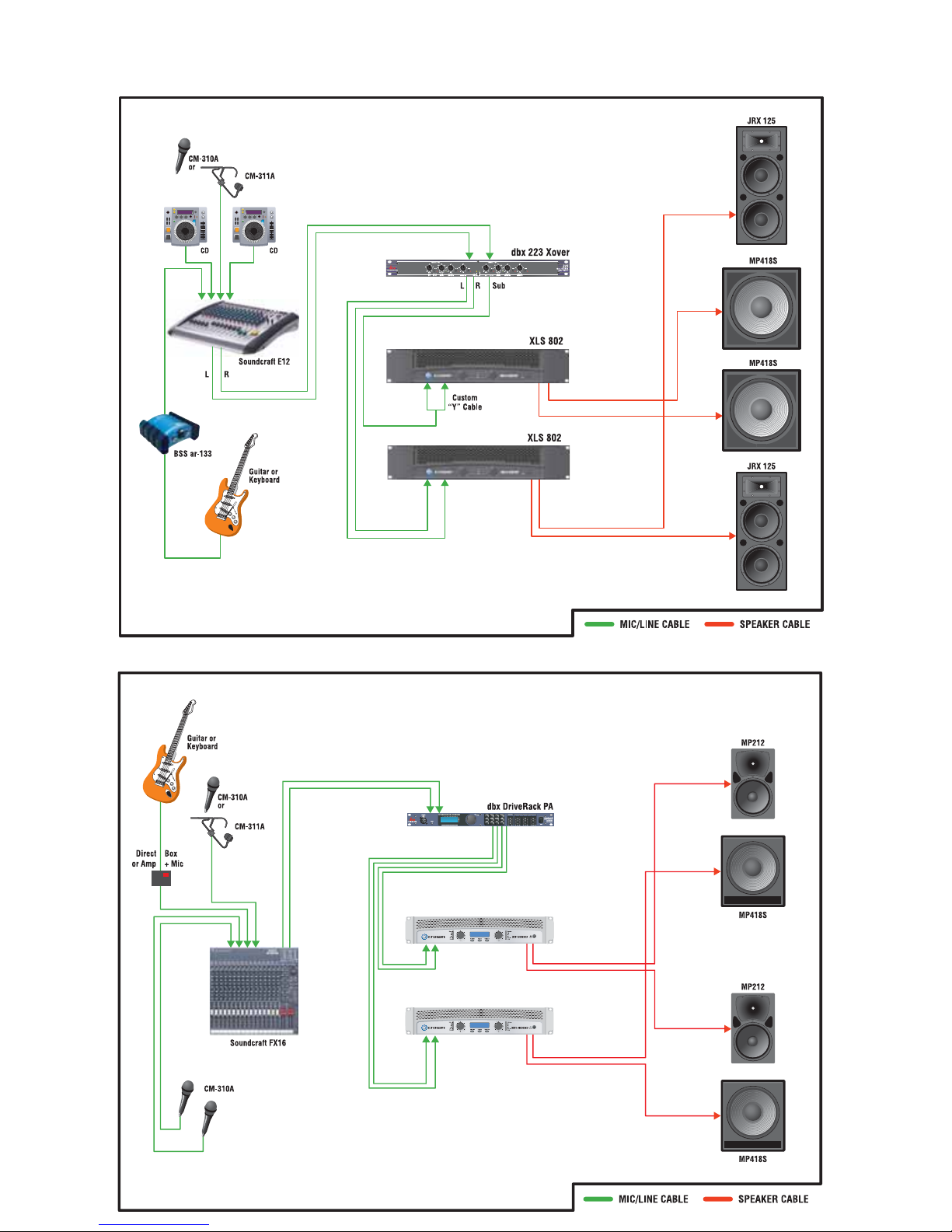
AMPLIFIERS PORTABLE PA
Product Applications
with Dual Subwoofers
Musician or DJ
Musician or DJ
Suggested for Medium Venues
XTi 1000
XTi 4000
Page 41
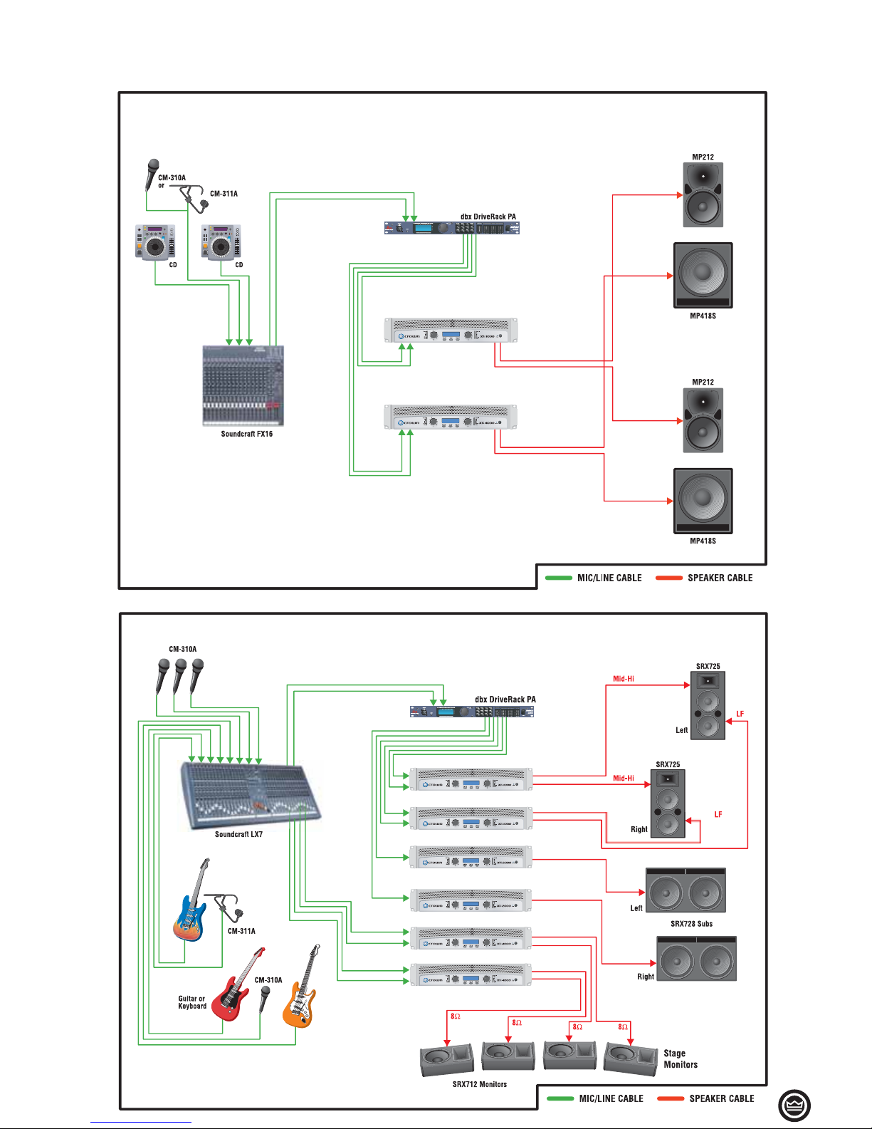
• 41
AMPLIFIERS PORTABLE PA
Product Applications
Regional Tour
Suggested for Large Venues
XTi 1000
XTi 4000
XTi 2000
(Bridge mode)
XTi 2000 (Bridge mode)
XTi 4000
XTi 4000
DJ
Suggested for Large Venues
XTi 1000
XTi 4000
Page 42
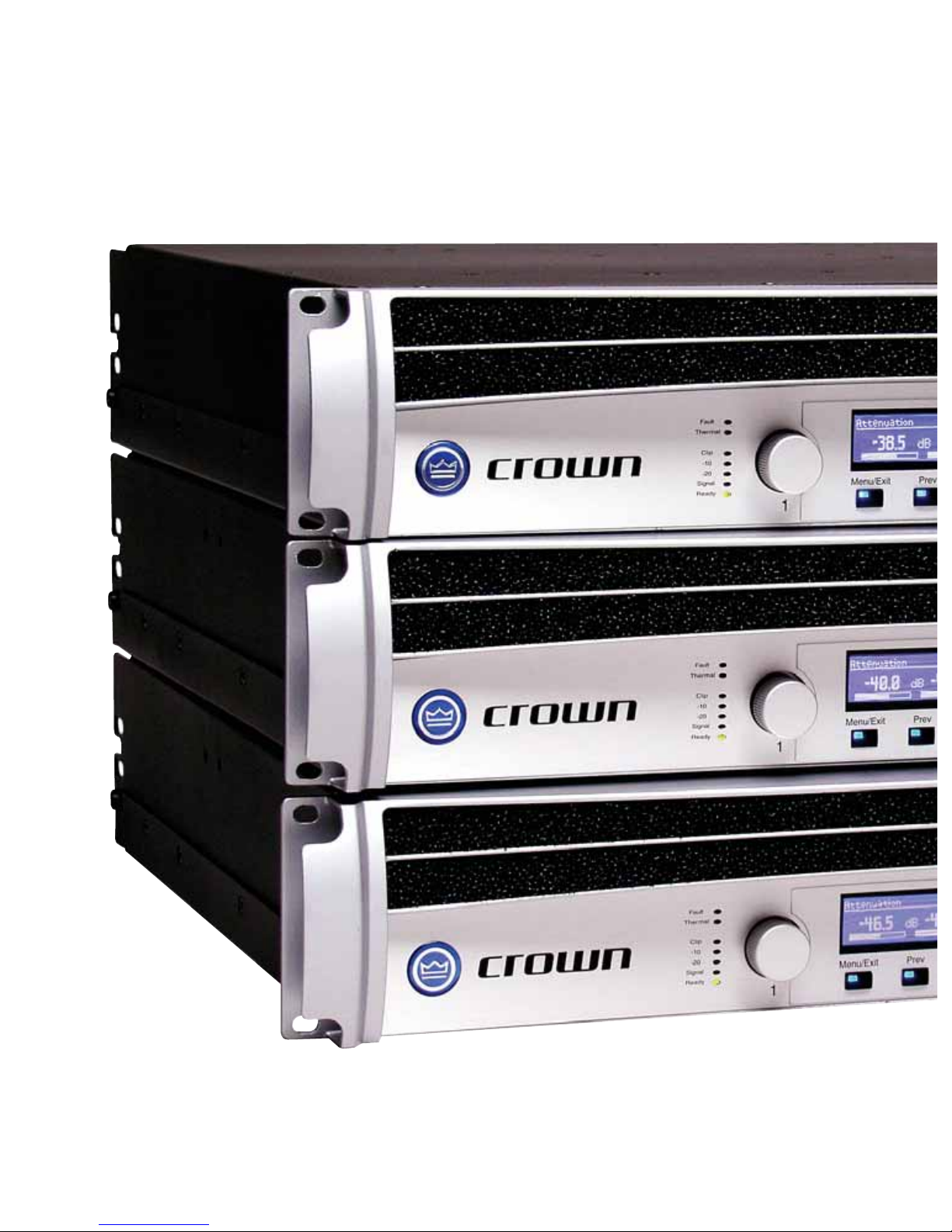
Page 43
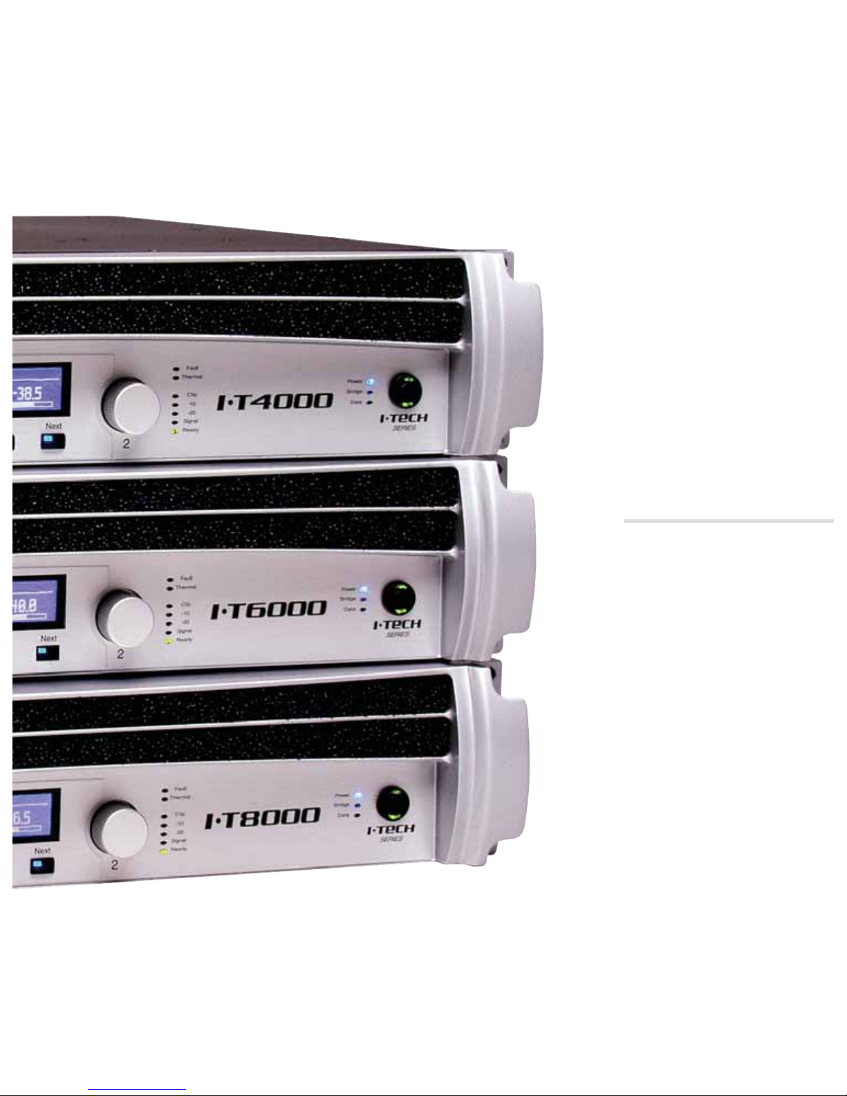
TOURING
I-Tech Series
MA-VZ Series
Macro-Tech 2402
Macro-Tech i Series
Page 44
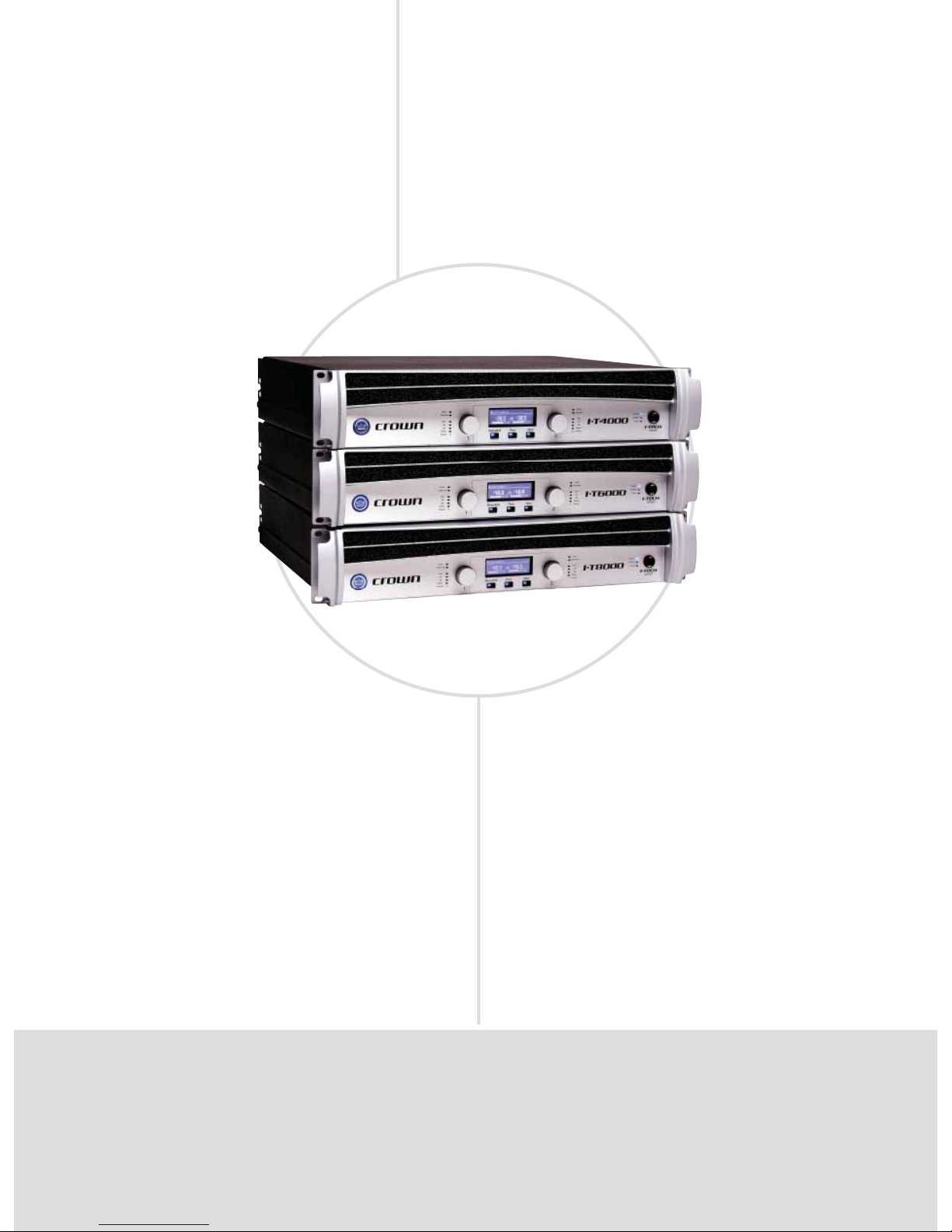
AMPLIFIERS TOURING
I-Tech Series: Excellence Without Compromise
I-T4000, I-T6000, I-T8000
Excellence
FEATURES
Unmatched power in a 2U lightweight chassis.
Global power supply with Power Factor Correction.
Onboard DSP.
Connects to Harman Pro HiQnet and Crown TCP/
IQ™ network.
LCD control screen allows easy setup, diagnostics,
and DSP presets for various loudspeakers.
•
•
•
•
•
POWER OUTPUT*
20 mS BURST 2-ohm Dual 4-ohm Dual 8-ohm Dual 4-ohm 8-ohm
Model 2-ohm Dual per ch.
(per channel) (per channel) (per channel) Bridge Bridge
I-T4000 2,565W 1,800W 2,000W 1,250W 3,600W 4,000W
I-T6000 4,570W 2,500W 3,000W 1,500W 5,000W 6,000W
I-T8000 5,900W 3,500W 4,000W 2,100W 7,000W 8,000W
*Guaranteed minimum power in watts at rated THD, 20 Hz - 20 kHz
Page 45

TOURING
• 45
www.crownaudio.com
SPECIFICATIONS
Performance
Frequency Response (at 1 watt, 20 Hz - 20 kHz):
±0.25 dB.
Signal to Noise Ratio (below rated full-bandwidth
power, A-weighted): > 105 dB.
Total Harmonic Distortion (THD) at full rated power:
< 0.35%.
Intermodulation Distortion (IMD) 60 Hz and 7 kHz at
4:1, from full rated output to –35 dB: < 0.35%.
Damping Factor (20 Hz to 100 Hz, 8 ohms): > 5000.
Crosstalk (below rated power, 20 Hz to 1 kHz):
> 80 dB.
Common Mode Rejection (CMR) (20 Hz to 1 kHz):
> 50 dB.
DC Output Offset (shorted input): < ±3 mV.
Input Impedance (nominal): 20 kilohms balanced, 10
kilohms unbalanced.
Maximum Input Level: +15 dBu or +22 dBu, depending on input sensitivity.
Latency (analog, digital inputs): 1.13 mS analog, 1.81
mS digital (96 kHz).
A/D, D/A Converters: 24-bit 96 kHz Cirrus Logic.
Digital Input: AES/EBU, 24-bit, 32-96 kHz. Onboard
sample rate converter.
Network: Onboard HiQnet and TCP/IQ, compatible
with standard 100 Mb Ethernet hardware.
DSP: 24-bit conversion with 32-bit, floating-point DSP
processing. Has 64 assignable filters with 9 different
filter types. Includes all-pass filters, over 2 seconds
of delay available per channel, and dual uncorrelatednoise and sine-wave generators.
Load Supervision: Monitors the average impedance
on the output of the amplifier. If the impedance falls
outside the specified high/low limits, this function
alerts the user via the front panel display, and via
System Architect
®
or IQwic™ software when amp is
on a HiQnet™ or IQ
®
Network.
Error Reporting: Reports clip errors, thermal errors,
fault conditions and load monitoring errors for each
channel via the front panel display and via Harman Pro
System Architect or IQwic software when amp is on a
HiQnet or IQ Network.
Attenuators: Speed-sensitive rotary encoders,
0.5 dB steps, range 0 to –100 dB.
Load Impedance (Note: Safe with all types of loads):
Stereo: 1/2/4/8/16 ohms.
Bridge Mono: 2/4/8 ohms.
Input Sensitivity for rated output/8 ohms: Adjustable
in 0.1V steps from 1.4V to 7.75V.
Voltage Gain:
I-T4000: 37.1 dB to 22.2 dB.
I-T6000: 37.9 dB to 23.0 dB.
I-T8000: 39.3 dB to 24.5 dB.
Required AC Mains: Universal AC input, 100-240VAC,
50/60 Hz (±15%). Maximum AC mains voltage
277VAC.
Front Panel Controls and Indicators
Power Switch: Push-on/push-off switch with built-in
green AC mains present indicator.
LCD Control Screen and Controls: These let the user
adjust the amplifier’s attenuation and muting, configure
the amp, set up and view error monitoring (such as
temperature and load supervision), and recall DSP presets. The presets allow the user to quickly reconfigure
the amp for various applications.
LCD Control Screen: Integrated LCD with white LED
backlight, controls amplifier setup and operation.
Normal mode: Attenuation in 0.5 dB steps, Mute/
Unmute, Front Panel Lockout.
Basic Menu: LCD Contrast, CH1 Sensitivity, CH2
Sensitivity, Speaker Preset, Dual/Bridge mode, Input Y.
Advanced Menu: Attenuator Limits, Attenuator Link,
Clip Limiter, Peak Voltage Limiter, Average Power
Limiter, Pink Noise Generator, AES/EBU Input Trim,
Input Source, Maximum Analog Input, Meter Display
Type.
Monitor Menu: Speaker Load, Thermal %, AC Voltage,
Operating Time, Firmware, Manufacturing Info,
Networking, Thermal Errors, Clip Errors, Low Limit
Load Errors, High Limit Load Errors, Line Voltage
Errors.
Menu/Exit Button: “Menu” enters the main menu.
“Exit” gets out of the Menu.
Next Button: Selects the next item in the Menu.
Prev Button: Selects the previous item in the Menu.
Level Controls (Encoders): These two knobs affect
the Channel-1 and Channel-2 output levels. They also
select Menu items and adjust parameter values that
are displayed on the LCD Control Screen.
Bridge Mode Indicator: Yellow LED illuminates when
the amplifier is set to Bridge-Mono mode.
Ready Indicator: Green LED, one per channel, illuminates when the channel is initialized and ready to produce audio output. Indicator is off when the amplifier
is in standby mode via the control software.
Signal Indicators: Three green LEDs per channel indicate the amplifier’s input and output signal levels.
Signal: input signal is above –40 dBu.
–20 dB: amplifier output is 20 dB below clipping.
–10 dB: amplifier output is 10 dB below clipping.
Clip Indicator: Red LED, one per channel, illuminates
when the channel’s output signal reaches the onset of
audible clipping. The Clip Indicator also will illuminate
during Thermal Level Control (TLC) limiting.
Thermal Indicator: Red LED, one per channel, illuminates when the channel has shut down due to thermal
stress or overload.
Fault Indicator: Red LED, one per channel, flashes
when the amplifier output channel has stopped operating.
Data Indicator: Yellow LED indicates HiQnet/IQ TCP/IP
data activity. Data indicator flashes only when the
amplifier is polled for data, or is polled to see whether
it is online.
Power Indicator: Blue LED indicates amplifier has
been turned on and AC power is available. The LED
will flash when the AC line voltage is 15% above or
below the nominal rated range.
AC Mains Present Indicator: Green indicator built
into power switch indicates AC power is present at the
power cord and the amplifier circuit breaker is in the
“on” position.
Back Panel Controls, Indicators and
Connectors
Reset Switch/Circuit Breaker: Resets circuit breaker
that protects power supply.
Data Indicator: Yellow LED indicates network data
activity. Data indicator flashes only when the amplifier is polled for data, or is polled to see whether it is
online.
Preset Indicator: Yellow LED flashes to signal the
number of the current preset if active.
Analog Input Connectors: A 3-pin female XLR connector for each channel.
Digital Input Connector: A 3-pin female XLR connector that accepts a digital signal in the AES/EBU format.
Network Connector: This Ethernet connector accepts
an RJ45 connector for HiQnet or TCP/IQ networking.
Built into the connector is a yellow LINK ACT indicator
that shows network activity, and a green 100Mb indicator that shows a 100Mb network connection.
Output Connectors: Two high-current, 50A Neutrik
®
Speakon
®
(mates with NL4FC or NL4), one per chan-
nel. Two pairs of high-current, 60A color-coded binding posts (for banana plugs, spade lugs or bare wire).
Two male XLR passive analog loop through. XLR
active/re-clocked AES/EBU digital loop through.
Power Connector: Standard 20 amp IEC inlet. Voltage
range is indicated above IEC inlet. Five cord sets supplied with amplifier (USA, UK, European, Australia,
India).
Construction: Cast aluminum front panel with integrated handles.
Cooling: Dual-zone, microprocessor controlled, continuously variable speed fans, front-to-back airflow.
Dimensions: 19 in. (48.3 cm) W x 3.5 in. (8.9 cm) H x
16.2 in. (41.1 cm) D.
Weight: 28 lb (12.7 kg) net, 36 lb (16.3 kg) shipping.
Included Accessories
Rear rack ears, rack screws, operation manual, power
cords, foam air filter.
Regulatory Certifications
Other Applications
T
he Crown® I-Tech Series offers amazing power, light weight and ease of use for touring sound and
installed sound applications. Onboard DSP provides a wide array of signal processing, greatly reduc-
ing the need for rack components and rack wiring. Onboard DSP features 24-bit, 96 kHz A/D and D/A
converters. All models are compatible with the HiQnet Network and TCP/IQ networking. Digital audio and
HiQnet/IQ control signals connect to the amp via a single CobraNet cable in optional new models, coming
soon. Push-button DSP presets simplify the setup for various loudspeaker arrays. The Global Power Supply
works anywhere in the world, and offers PFC (Power Factor Correction). I-Tech amplifiers have the highest output voltage in the industry (200V peak), which provides clean transient peaks. The 3rd-generation
patented Class I (BCA®) circuitry couples power efficiently to the load and allows low AC current drain. A
front-panel control screen shows advanced diagnostics and status information.
Page 46
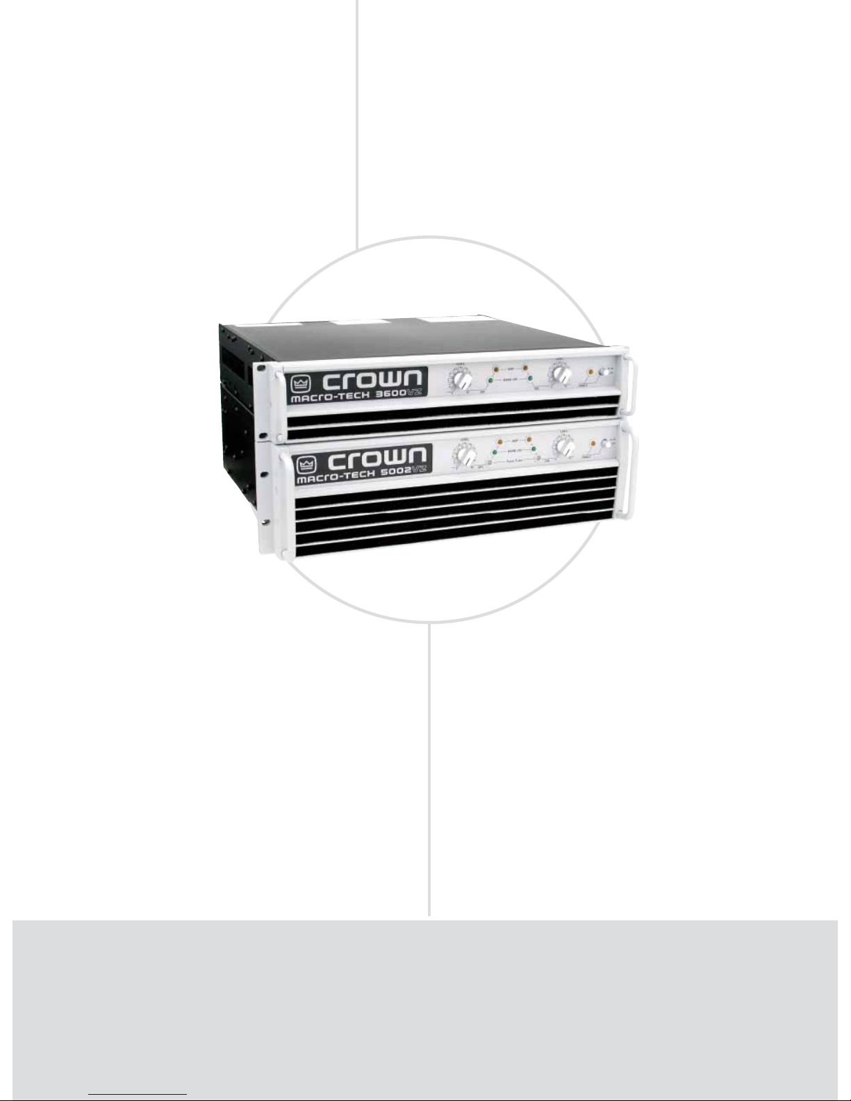
AMPLIFIERS TOURING
Macro-Tech VZ® Series: Advanced VZ Technology
Macro-Tech 3600VZ, Macro-Tech 5002VZ
VZ Technology
FEATURES
Crown’s Grounded Bridge™ design provides lower distortion and superior
reliability.
Patented ODEP® (Output Device Emulation Protection) circuitry compensates for overheating and overload to keep the amplifi er working when
others would fail.
Articulated VZ
®
power supplies for each channel provide excellent crosstalk
characteristics and the best power matching to your load.
MA-3600VZ works with PIP™ modules and MA-5002VZ works with PIP2™
modules that tailor the amplifi er to suit specifi c applications.
Two mono modes (Bridge-Mono and Parallel-Mono) for driving a wide
range of load impedances.
•
•
•
•
•
POWER OUTPUT*
2-ohm Dual 4-ohm Dual 8-ohm Dual 4-ohm 8-ohm
Models (per channel) (per channel) (per channel) Bridge Bridge
MA-3600VZ 1,800W 1,565W 1,120W 3,505W 3,140W
MA-5002VZ 2,500W 2,000W 1,300W 5,000W 4,000W
*Maximum average power in watts at 0.1% THD, 1 kHz.
Page 47

TOURING
• 47
www.crownaudio.com
O
ur patented variable impedance (VZ®) technology permits the Macro-Tech® 3600VZ and the Macro-
Tech 5002VZ to dynamically adapt to both signal and load requirements, providing the best power
match to the widest range of loads. These models pack large amounts of power into a compact package
while achieving ultra-low distortion and without generating excessive heat. Detented controls, PIP™
expandability and comprehensive status indicators are included. The Macro-Tech 5002VZ’s universal
power supply adapts to available voltages around the world.
SPECIFICATIONS
Performance
Frequency Response (at 1 watt) 20 Hz to 20 kHz:
±0.1 dB.
Phase Response (at 1 watt, 10 Hz to 20 kHz): ±10
degrees.
Signal-to-Noise Ratio (below rated full bandwidth
power), A-weighted: > 105 dB.
Total Harmonic Distortion (THD) (at rated power):
MA-3600VZ: 20 Hz to 1 kHz: < 0.05%.
20 kHz: < 0.1%.
MA-5002VZ: < 0.05% true THD
Intermodulation Distortion (IMD) (60 Hz and
7 kHz at 4:1):
MA-3600VZ (from 368 milliwatts to full
rated output): < 0.05%.
MA-5002VZ (from rated power to 35 dB
below rated power at 8 ohms): < 0.05%.
Damping Factor (8 ohm) 10 Hz to 400 Hz: >1000.
Voltage Gain (8-ohm load, rated output at 1 kHz,
at maximum level setting, ±6% or ±0.5 dB):
MA-3600VZ: 124.6:1 or 41.9 dB at 0.775-volt
sensitivity; 69.2:1 or 36.8 dB at 1.4-volt
sensitivity; 20:1 or 26 dB at 26-dB sensitivity.
MA-5002VZ: 132.1:1 or 42-dB at 0.775-volt
sensitivity; 71:1:1 or 37 dB at 1.4-volt sensitivity;
20:1 or 26 dB at 26-dB sensitivity.
Controlled Slew Rate: > 30 volts/microsecond.
Input Impedance: 20 kilohms balanced, 10
kilohms unbalanced.
Load Impedance:
MA-3600VZ: Safe with all types of loads. Rated
for 2 to 16 ohms in Stereo, 4 to 16 ohms in
Bridge-Mono, and 1 to 4 ohms in Parallel-Mono.
MA-5002VZ: Safe with all types of loads. Rated
for 2 to 8 ohms in Stereo, 4 to 16 ohms in
Bridge-Mono, and 1 to 4 ohms in Parallel-Mono.
DC Output Offset (shorted input): < ±10 millivolts.
Required AC Mains (MA-3600VZ):
50/60 Hz; 100, 120, and 230VAC (±10%) units are
available. 230VAC, 50/60 Hz units can be used with
220 and 240VAC. 100VAC and 120VAC units can
draw up to 30 amps; 230VAC units can draw up to
15 amps. Current, voltage and frequency requirements are provided on unit’s back panel.
Required AC Mains (MA-5002VZ):
50 or 60 Hz; 100, 120, 200, 208, 230, 240VAC
(±10%). Current, voltage and frequency requirements are provided on unit’s back panel.
Power Draw at Idle: 90 watts or less.
Front Panel Controls and Indicators
Level: Rotary detented level control, one for each
channel.
Enable: Push button used to turn the amplifier on
and off.
Enable LED: Amber LED indicates amplifier is on
and AC power is available.
Signal/IOC: Green LED for each channel flashes to
show amplifier output. If a channel’s output waveform differs from its input by 0.05% or more, the
indicator flashes brightly to show distortion.
ODEP: Amber LED for each channel shows
thermal-dynamic energy reserve. A lit indicator
shows available reserve energy. If a channel has
no reserve, its indicator will dim in proportion to
ODEP limiting.
ILoad/ILimit (MA-5002VZ only): Two-color
(green/red) LED for each channel. Green indicates
load current flowing out the amplifier; red indicates
maximum current is being delivered to the load.
Back Panel Controls and Connectors
Compressor (MA-5002VZ only): Controls the
channel’s error-driven compression. Selections
include Off; Fast (4-millisecond attack, 300-millisecond release), and Slow (12-millisecond attack,
600-millisecond release).
Input Ground Lift (MA-5002VZ only): A two-position switch used to isolate the input audio signal
grounds from the AC (chassis) ground to help
prevent ground loops.
Loudspeaker Offset Integration (MA-5002VZ
only): Two-position switch for each channel
turns on or off the loudspeaker protection, which
protects against DC, off-center woofer cone movement, and unwanted subsonic and ultrasonic
frequencies.
Sensitivity: Switch for both channels selects input
sensitivity: 0.775 volts or 1.4 volts for standard 1kHz power, or a 26 dB voltage gain.
Stereo/Mono: Switch selects Stereo, Bridge-Mono
or Parallel-Mono mode.
VZ Mode (MA-5002VZ only): Switch for each
channel controls the switching mode of the VZ
power supplies.
Input Connectors
3-pin female XLR and female TRS for each channel.
Output Connectors
MA-3600VZ: Two sets of color-coded binding
posts for banana plugs or bare wire (European
models do not accept banana plugs).
MA-5002VZ: High-current output block
accepts banana plugs, spade lugs or bare wire.
A detachable output cover protects against
accidental short circuits and dangerous electrical shock.
Protection
Macro-Tech amplifiers are protected against
shorted, open or mismatched loads; overloaded
power supplies; excessive temperature, chain
destruction phenomena, input overload damage
and high-frequency blowups. They also protect
loudspeakers from input/output DC and turn-on/
turn-off transients.
Cooling
Internal heat sinks, forced-air cooling for rapid heat
dissipation.
Dimensions
EIA Standard 19-inch (48.3-cm) rack mount width
(EIA RS-310-B),
MA-3600VZ: 3.5-inch (8.9-cm) height and
16-inch (40.6-cm) depth behind the mounting
surface.
MA-5002VZ: 5.25-inch (13.3-cm) height and
15.875-inch (40.3-cm) depth behind the mount
ing surface.
Weight
Net Weight,
MA-3600VZ: 55 lbs. 1.5 oz. (25.0 kg).
MA-5002VZ: 77 lbs. 9 oz. (35.2kg).
Shipping Weight,
MA-3600VZ: 63 lbs. 10 oz. (28.9 kg).
MA-5002VZ: 88 lbs. 10 oz. (40.2 kg).
Accessories
IQ Network Accessories: The MA-5002VZ
accepts all current PIP2 modules. The MA-3600VZ
can accept PIP LITE module when paired with the
IQ-PIP USP2 Adapter Kit (some functionality will
be limited).
Regulatory Certifications
Other Applications
All measurements apply to units in Stereo mode with
8-ohm loads and rated input sensitivity unless otherwise specified.
MA-3600VZ
only
MA-5002VZ
only
Page 48
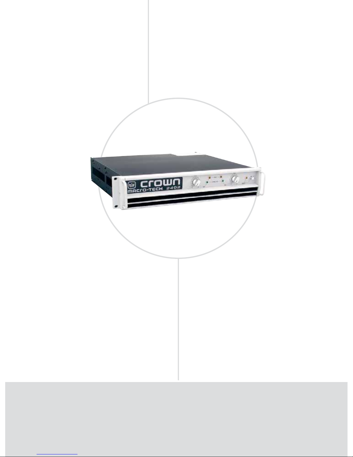
AMPLIFIERS TOURING
Macro-Tech 2402: Advanced Reinforcement
Macro-Tech 2402
Advanced
FEATURES
Enhanced PIP2™ (Programmable Input Processor) connector
accepts new accessory modules that tailor the amplifi er for specifi c
applications.
Balanced XLR and 1/4-inch phone jacks for each channel on the
standard PIP-FXQ module.
Full Protection from shorted, open and mismatched loads, general
over-heating, DC, high-frequency overloads, and full internal fault
protection are provided by our “Quad-Mute” protection scheme.
Two mono modes (Bridge-Mono and Parallel-Mono) for driving
a wide range of load impedances.
•
•
•
•
POWER OUTPUT*
2-ohm Dual 4-ohm Dual 8-ohm Dual 4-ohm 8-ohm
Model (per channel) (per channel) (per channel) Bridge Bridge
MA-2402 1,050W 800W 520W 2,070W 1,585W
*Maximum average power in watts at 0.1% THD, 1 kHz.
Page 49

TOURING
• 49
www.crownaudio.com
T
he Macro-Tech® 2402 amplifier delivers superior sonic accuracy and enormous amounts of power
from a low-profile design—perfect for touring and fixed installations. Crown’s patented ODEP
®
(Output Device Emulation Protection) and Grounded Bridge™ output circuitry enhance reliability
and virtually eliminate distortion. Dual, Bridge-Mono or Parallel-Mono modes allow you to optimize
power to your loads, while IOC
®
(Input/Output Comparator) circuitry acts as a supersensitive distor-
tion meter, giving proof of distortion-free performance.
SPECIFICATIONS
Performance
Frequency Response (at 1 watt) 20 Hz to 20 kHz:
±0.1 dB.
Phase Response (at 1 watt, 10 Hz to 20 kHz):
±10 degrees.
Signal-to-Noise Ratio (below rated full bandwidth
power), A-weighted: > 105 dB.
Total Harmonic Distortion (THD) (at rated power),
20 Hz to 1 kHz: < 0.05%.
At 20 kHz: < 0.1%.
Intermodulation Distortion (IMD) (60 Hz and 7
kHz at 4:1) from 163 milliwatts to full bandwidth
power: < 0.05%.
Damping Factor (8 ohm) 10 Hz to 400 Hz: >1000.
Crosstalk (below rated power), 20 Hz to 1 kHz:
> 85 dB.
Voltage Gain (at maximum level setting, ±6%):
38 dB gain at 0.775 volt sensitivity; 33 dB gain at
1.4-volt sensitivity; 26 dB gain at maximum level
setting.
Controlled Slew Rate: >13 volts/microsecond.
Input Impedance: (balanced, unbalanced): 20 k
ohms, 10 k ohms.
Load Impedance: Safe with all types of loads.
Rated for 2 to 16 ohms in Stereo, 4 to 8 ohms in
Bridge-Mono, and 1 to 4 ohms in Parallel-Mono.
Required AC Mains (±10%): 50/60 Hz, 100240VAC.
Power Draw at Idle: 100 watts or less.
Front Panel Controls and Indicators
Enable: A push button used to turn the amplifier
on and off.
Level: A rotary control for each channel with
31 detents used to control the output level.
Enable LED: This amber indicator shows the on/off
status of the low-voltage power supply.
Signal/IOC: Each channel has a green indicator
that flashes to show amplifier output. If a channel’s
output waveform differs from its input by 0.05% or
more, the indicator flashes brightly to show distortion. This function provides proof of distortion-free
performance. In Parallel-Mono mode, the Channel
2 light stays on.
ODEP: Each channel has an amber indicator that
shows thermal-dynamic energy reserve. Normally,
each ODEP indicator is lit to show available reserve
energy. In the rare event that a channel has no
reserve, its indicator will dim in proportion to ODEP
limiting. An ODEP indicator may also turn off under
other conditions.
Back Panel Controls and Connectors
Stereo/Mono: A three-position back panel switch
used to select Stereo, Bridge-Mono or ParallelMono mode.
Reset: A push button for each channel, used to
reset the circuit breaker that protects each power
supply.
Input Ground Lift: This switch on the PIP2-FXQ is
used to isolate input signal grounds from chassis
ground to prevent ground loops.
Sensitivity: A three-position switch inside the
PIP™ compartment used to select the input sensitivity for both channels: 0.775 volts or 1.4 volts for
standard 1 kHz power, or a 26 dB voltage gain.
Input Connectors: Factory-installed PIP2-FXQ
provides one 3-pin female XLR connector for each
channel in parallel with one balanced 1/4-inch
phone jack connector for each channel.
Output Connectors: Two sets of color-coded binding posts for banana plugs, spade lugs or bare wire
(European models do not accept banana plugs).
Protection
Macro-Tech amplifiers are protected against shorted,
open or mismatched loads; overloaded power supplies; excessive temperature, chain destruction phenomena, input overload damage and high-frequency
blowups. They also protect loudspeakers from input/
output DC and turn-on/turn-off transients.
Cooling
Flow-through ventilation from front to side panels.
Internal heat sinks with forced-air cooling for rapid,
uniform heat dissipation.
Dimensions
EIA Standard 19-inch (48.3-cm) rack mount width
(EIA RS-310-B), 3.5-inch (8.9-cm) height and 16inch (40.6-cm) depth behind the mounting surface.
Weight
Net Weight: 51 lbs. 12 oz. (23.5 kg).
Shipping Weight: 65 lbs. (29.5 kg).
Accessories
Cooling fan option, level control shaft lock.
Crown PIP and PIP2 modules which allow networking via HiQnet or TCP/IQ.
Regulatory Certifications
Other Applications
Note: All measurements apply to units in Stereo mode
with 8-ohm loads and rated input sensitivity unless
otherwise specified.
Page 50
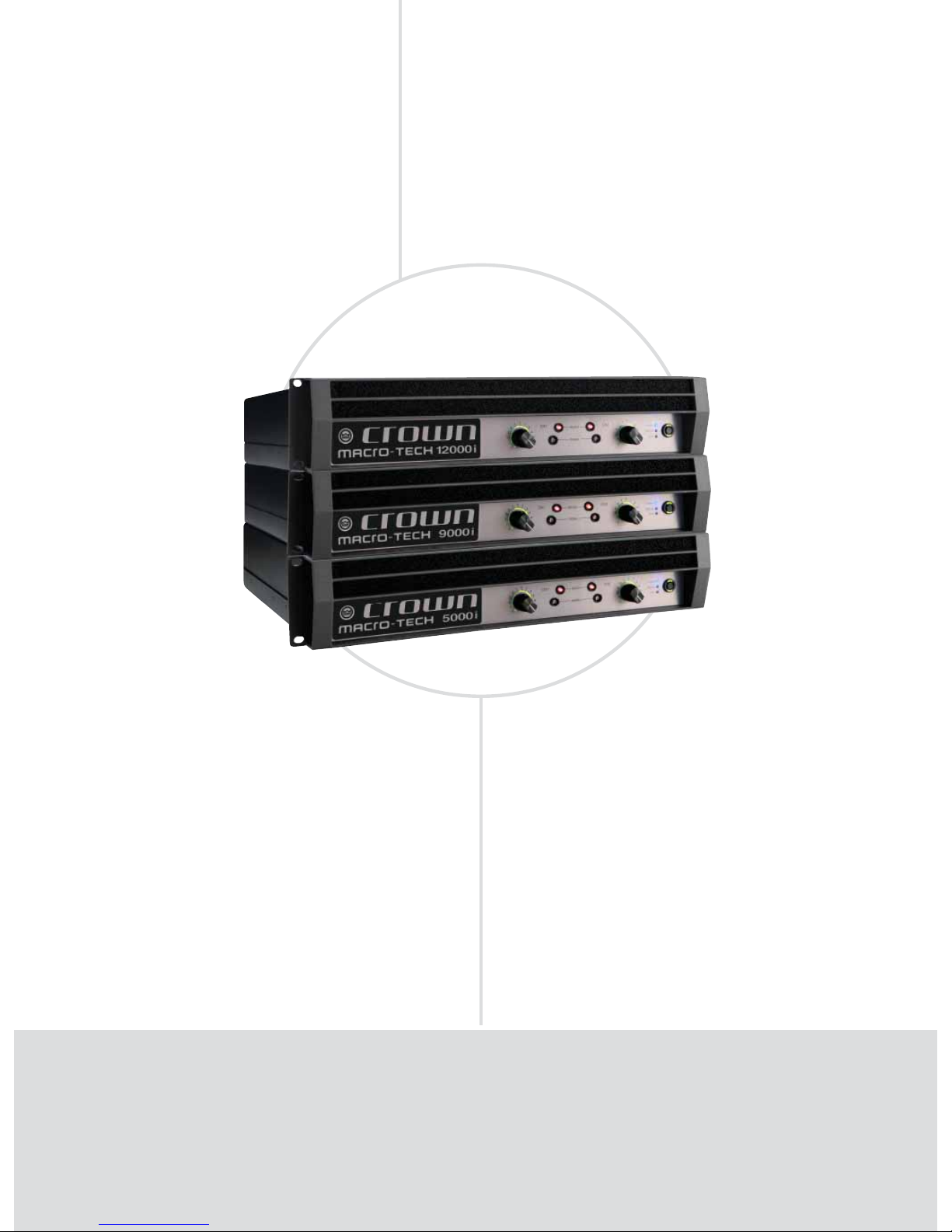
AMPLIFIERS TOURING
Macro-Tech i Series: The Legend Continues
Macro-Tech i Series
The Legend Continues
FEATURES
• The Macro-Tech® i Series continues the Crown® Macro-Tech legacy of
unparalleled sonic accuracy and detail, putting sound quality above all else
• Patented, cutting-edge Class-I circuitry gets more power out of an amplifier
with less waste
• Rugged construction ensures that all Macro-Techs are built to withstand
years of abuse on the road
• Global Power Supply — designed to deliver maximum power no matter what
country you work in
• Built-in load, line voltage, input and output monitoring
• Standard Ethernet networking via System Architect® lets system operators
monitor and control the amplifier from any location
POWER OUTPUT*
20 mS BURST 2-ohm Dual 2-ohm Dual 4-ohm Dual 8-ohm Dual 4-ohm 8-ohm
Model 2-ohm Dual (per ch.)
(per channel) (per channel, 1 kHz) (per channel) (per channel) Bridge Bridge
MA-5000i 2,565W 1,800W 1,800W 2,000W 1,250W 3,600W 4,000W
MA-9000i 4,570W 2,500W 2,500W 3,000W 1,500W 5,000W 6,000W
MA-12000i 5,900W 3,500W 3,500W 4,000W 2,100W 7,000W 8,000W
*Guaranteed minimum power in watts at rated THD, 20 Hz - 20 kHz
NEW
NEW
NEW
Page 51

TOURING
• 51
www.crownaudio.com
T
he Crown Macro-Tech i Series amplifiers continue the Macro-Tech legacy of unparalleled sonic accuracy and detail, putting sound quality above all else. Their patented, cutting-edge Class-I circuitry gets
more power out of an amplifier with less waste. Each model features a Global Power Supply designed
to deliver maximum power in any country. The i Series offers studio-quality analog signal processing
with built-in load, line voltage, input and output monitoring. Standard Ethernet networking via System
Architect provides integrated monitoring and control to give system operators access to the system from
any location.
SPECIFICATIONS
Performance
Frequency Response
(at 1 watt, 20 Hz - 20 kHz into 8 ohms): ±0.25
dB.
Signal to Noise Ratio
(below rated full-bandwidth power, A-weighted):
>110 dB.
Total Harmonic Distortion (THD)
(at 2 watts into 8 ohms): < 0.1%.
Total Harmonic Distortion (THD)
Plus Noise (at full rated power):
< 0.35%, 20 Hz to 20 kHz.
Intermodulation Distortion (IMD)
(60 Hz and 7 kHz at 4:1,
from full rated output to –30 dB): < 0.35%.
Damping Factor (20 Hz to 100 Hz at 8 ohms):
> 5000.
Crosstalk (below rated power, 20 Hz to 1 kHz):
> 80 dB.
Common Mode Rejection (CMR)
(20 Hz to 1 kHz): 55 dB, typically >70 dB.
DC Output Offset (shorted input): < ± 3 mV.
Input Impedance (nominal):
10 kilohms balanced, 5 kilohms unbalanced.
Maximum Input Level: +20 dBu typical.
Network: Onboard HiQnet™, compatible with
standard 100 Mb Ethercom hardware.
Load Impedance: (Note: Safe with all types of
loads)
Stereo: 1/2/4/8/16 ohms. Bridge Mono: 2/4/8
ohms.
Input Sensitivity (referenced to 8 ohm rated
output): 1.4V, 32 dB gain, and 26 dB gain.
Voltage Gain (referenced to 8 ohm rated output):
MA-5000i: 37.1 dB to 22.2 dB
MA-9000i: 37.9 dB to 23.0 dB
MA-12000i: 39.3 dB to 24.5 dB
Required AC Mains: Universal AC input, 100240VAC, 50/60 Hz (±10%). Maximum AC mains
voltage 264VAC.
AC Line Connector: Five cordsets supplied with
amplifier (USA, UK, European, Australia, India).
Front Panel Controls and Indicators
Bridge Mode Indicator: Amber LED illuminates
when the amplifier is set to Bridge-Mono mode.
Ready Indicator: Red LED, one per channel.
On (bright): Ready.
On (dim): Onset of compression.
Off: Thermal failure.
Signal Indicators: One green LED per channel.
Solid green: Input signal is above –40 dBu.
Bright green: Channel’s output signal has
reached the onset of audible clipping.
Power Indicator: Blue LED indicates amplifier
has been turned on and AC power is available.
The LED will flash when the AC line voltage is
10% above or below the nominal rated value.
Data Indicator: Yellow LED on front panel
indicates network data activity. Data indicator
flashes only when the amplifier is polled for
data, or is polled to see whether it is online
Power Switch: Push-on/push-off switch with
built-in green AC mains present indicator.
Volume Control: Precision detented attenuator
with 31 steps, press-and-hold mute function.
Volume Control LED Ring: A ring of green LEDs
around each volume control show the position
of the control. Entire ring flashes when channel
is muted. Can be converted to be a level meter.
Back Panel Controls, Indicators and Connectors
Power Cord Connector: Detachable 20 amp IEC
inlet. Cord locks with suppliled cord retention
clip. Voltage range is indicated above IEC inlet.
Reset Switch/Circuit Breaker: If the current
draw of the amplifier exceeds safe limits, this
breaker automatically disconnects the power
supply from the AC mains. The switch resets
the circuit breaker.
Output Connectors: Two high-current, 50A
Neutrik® Speakon® NL4MLP (mates with
NL4FC or NL4), one per channel. Ch 1
Speakon® is wired with Ch 1 and Ch 2 outputs
for use with single 4-conductor cable. Two pairs
of high-current, 60A color-coded 5-way binding
posts (for banana plugs, spade lugs or bare
wire).
Analog Input Connectors: A 3-pin female XLR
connector for each channel.
Analog Loop Thru Connectors: Two male XLR
passive analog loop through.
Mode Switch/Indicator: Sets amplifier to
Stereo, Bridge, or Input Y mode. OFF=Stereo,
YEL=Bridge, GRN=Y.
Network Connector: This Neutrik® Ethercon
connector accepts an RJ-45 connector for
HiQnet™ networking. Next to the connector is
a yellow LINK ACT indicator that shows network activity, and a green 100Mb indicator that
shows a 100Mb network connection.
Data Indicator: Yellow LED on back panel indicates network data activity. Data indicator flashes only when the amplifier is polled for data, or
is polled to see whether it is online.
Preset Indicator: Green/yellow LED flashes to
signal the number of the current preset. LED is
green if current preset is active, or is yellow if
current preset is modified.
Input Sensitivity Switch: Three-position switch
providing 1.4V, 32 dB, and 26 dB settings for
both channels.
Firmware/Software
Firmware can be updated at www.crownaudio.
com > Support > Downloads.
Software features: Same as PIP-Lite module
(except no Listen Bus): User Presets, Clip Event
Monitor, Input Signal Level Monitor, Output
Signal Level Monitor, Thermal Headroom Level
Monitor, Power/Standby Control, Signal Mute,
Polarity Inverter, Input Signal Fader, Dynamic
Gain Monitors (Ghost Faders), Amplifier
Information, User and Channel Labels, Amplifier
Mode, Amplifier Output Mode, Line Voltage
Monitor, Error Reporting, Auto Standby, Input
Signal Compressor/Limiter, Peak Voltage
Limiter, Average Power Limiter, Clip Eliminator,
Thermal Limiter, Limiter Tie, Load Supervision.
Construction
Cooling: Dual-zone, microprocessor controlled,
continuously variable speed fans, front-to-back
airflow.
Front Panel: Cast aluminum with integrated
handles.
Dimensions: 19 in. (48.3 cm) W x 3.5 in. (8.9
cm) H x 16.2 in. (41.1 cm) D.
Weight: 28 lbs (12.7 kg) net, 36 lbs (16.3 kg)
shipping.
Protection: Amplifier is protected against reactive
loads, faults and shorts. If one channel experiences a catastrophic failure, the entire amplifier
will shut down.
Included Accessories: Rear rack ears, rack
screws, operation manual, power cords, foam
air filter.
Regulatory Certifications
Other Applications
Note: All measurements apply to units in Stereo mode
with 8-ohm loads and rated input sensitivity unless
otherwise specified.
Page 52
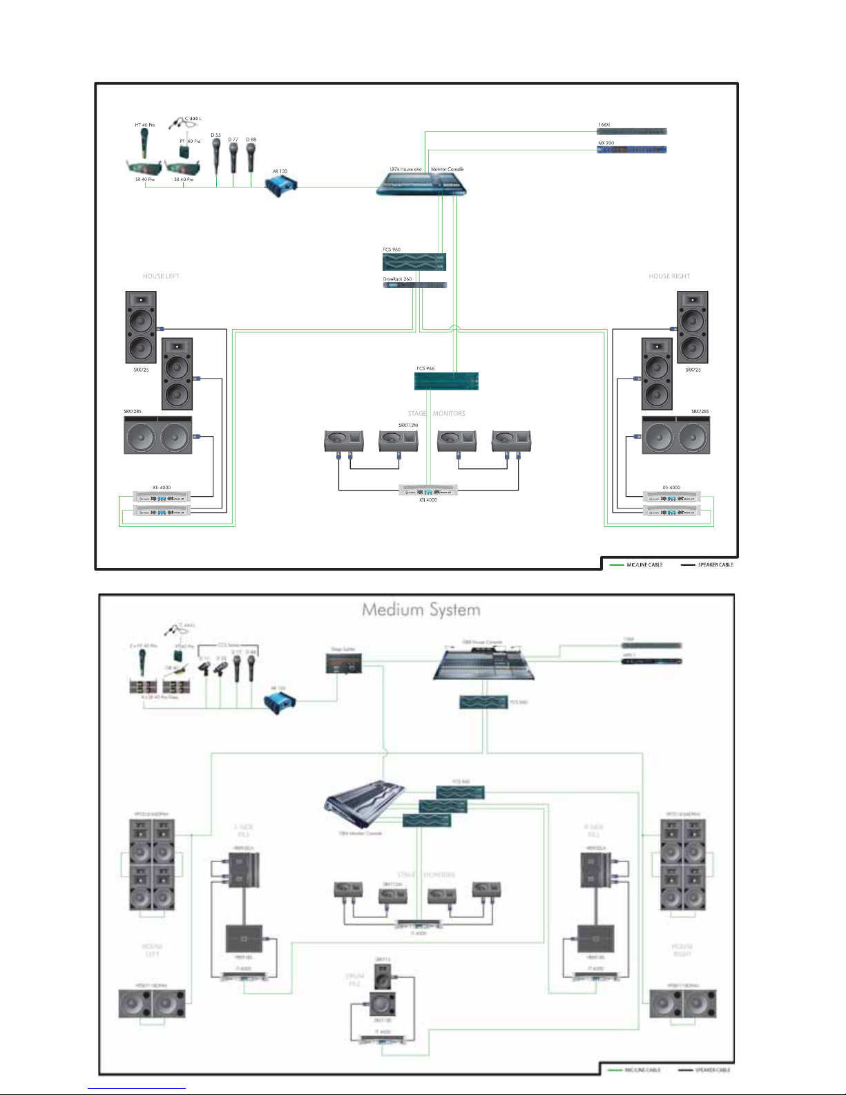
Small System
AMPLIFIERS TOURING
Product Applications
Page 53
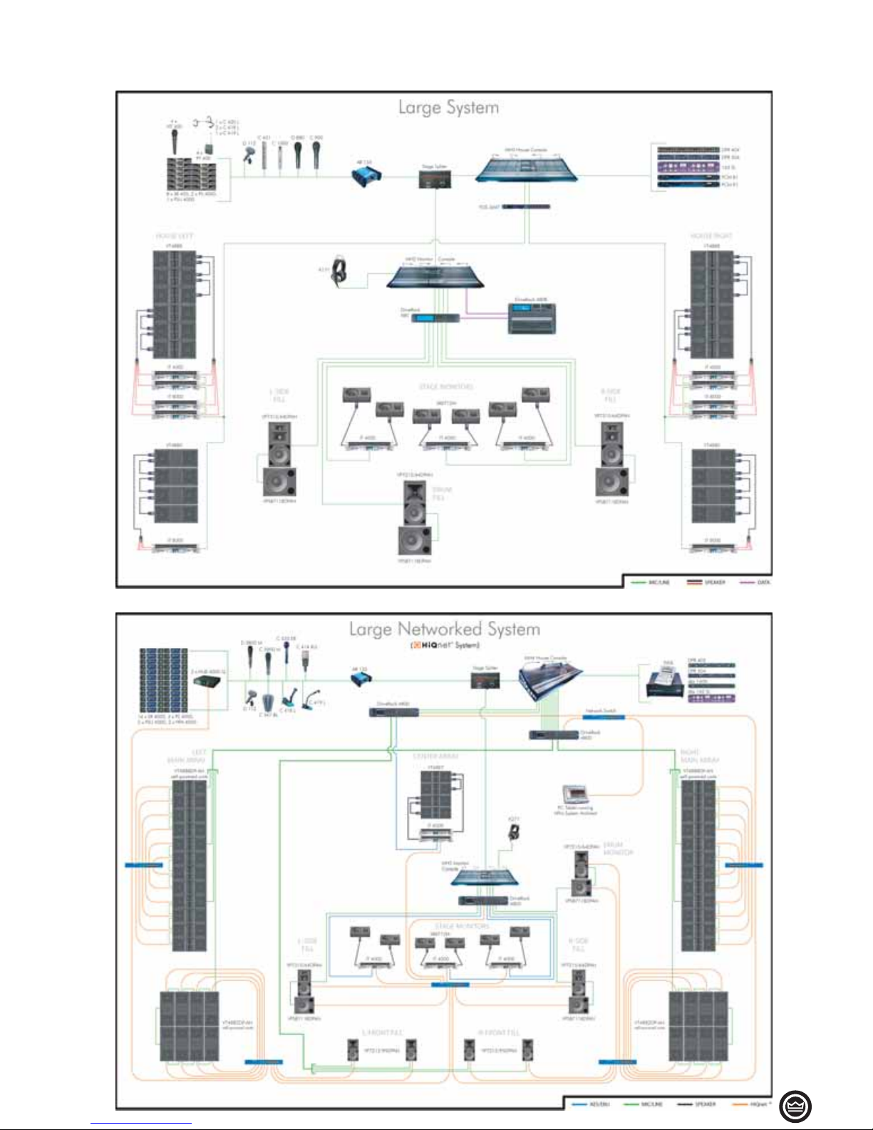
• 53
AMPLIFIERS TOURING
Product Applications
Page 54
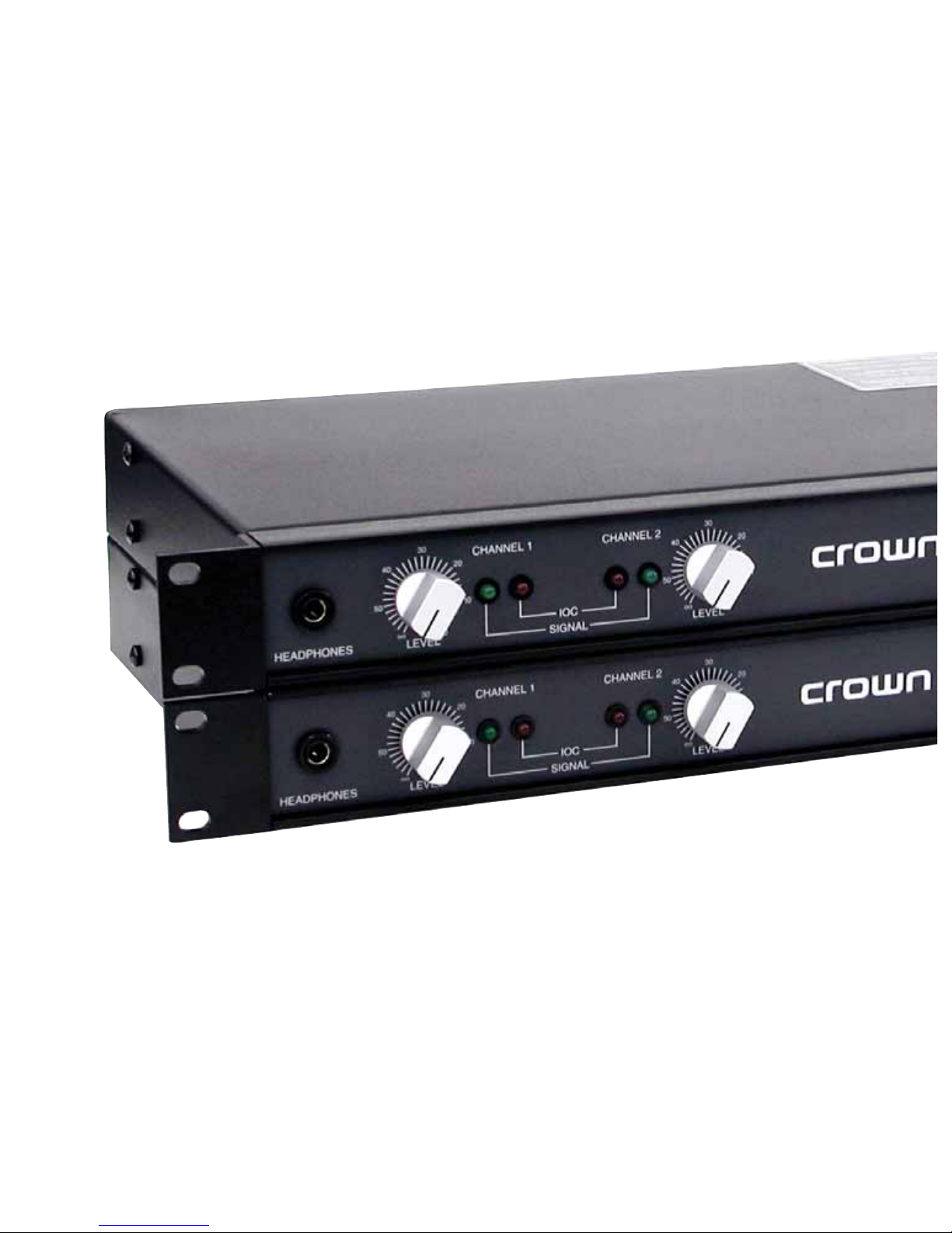
Page 55
RECORDING &
BROADCAST
D Series
Page 56
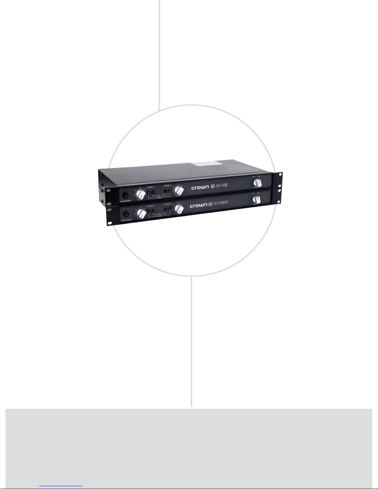
Tried & True
FEATURES
Powerful AB+B class circuitry yields maximum effi ciency
with minimum crossover “notch” distortion.
IOC® (Input/Output Comparator) alerts of any distortion that
exceeds 0.05% to provide proof of distortion-free performance.
Ultra-low harmonic and intermodulation distortion result
in the best dynamic transfer function in the industry.
Very low noise and wide dynamic range exceed the
audio specifi cations for digital compact discs (CDs).
Convection cooling system dissipates heat through the heat
sinks and chassis for optimal cooling and maintenance-free
operation.
Front-panel headphone jack.
•
•
•
•
•
•
AMPLIFIERS RECORDING & BROADCAST
D Series: Long-Term Favorites
D-45, D-75A
POWER OUTPUT*
4-ohm Dual 8-ohm Dual 16-ohm Dual 8-ohm 16-ohm
Models (per channel) (per channel) (per channel) Bridge Bridge
D-45 35W 25W 20W 70W 50W
D-75A 55W 40W 25W 110W 80W
*Maximum average power in watts at 0.1% THD, 1 kHz.
Page 57

RECORDING & BROADCAST
• 57
www.crownaudio.com
T
he D-45 and D-75A are long-term standards. They are perfect for moderate power applications
such as recording or broadcast studio near-field monitoring, video suite audio monitoring, a
recording/broadcast headphone amp or a small paging system. Convection cooled, the highly reliable D Series is protected against shorted, open, mismatched or low-impedance loads.
SPECIFICATIONS
Performance
Frequency Response (at 1 watt) 20 Hz to 20 kHz:
±0.1 dB.
Phase Response (from 20 Hz to 20 kHz at 1 watt):
+10 to –15 degrees.
Signal-to-Noise Ratio below rated power (20 Hz
- 20 kHz): 106 dB.
Total Harmonic Distortion (THD) at full bandwidth
power: 0.05% from 20 Hz to 20 kHz.
Intermodulation Distortion (IMD) (60 Hz and
7 kHz at 4:1)
from 0.25 watts to full bandwidth power: < 0.01%.
from 0.01 to 0.25 watts: < 0.05%.
Damping Factor, from DC to 400 Hz: > 400.
Crosstalk (below rated power): 100 Hz to 1 kHz,
>100 dB.
Input Impedance (nominally balanced, nominally
unbalanced): 20 k ohms, 10 k ohms.
Input Sensitivity: Configurable for 26 dB gain or
0.775-volt sensitivity.
Load Impedance: Safe with all types of loads.
Rated for 4 to 16 ohms in Dual mode, 8 to 16
ohms in Bridge-Mono mode.
AC Line Voltage and Frequency Configurations
Available (±10%): 100, 120, 220 and 240 VAC,
50 to 400 Hz for international units (depending on the transformer configuration). North
American 120 VAC, 60 Hz units are not convertible and can only be used at the specified voltage
and frequency. All units draw 15 watts or less
when idle.
Front Panel Controls and Indicators
Power: A two-position rotary on/off switch.
Level: An independent detented front-panel level
control for each channel.
Dual/Mono: A jumper located inside the amplifier
selects between dual and mono operation.
Signal Presence: The green front-panel indicator
for each channel flashes synchronously with the
channel’s output signal to indicate its presence.
Input/Output Comparator: The red Input/Output
Comparator (IOC) indicator for each channel flashes if any type of distortion reaches 0.05%.
Back Panel Connectors
Input Connectors: A balanced 3-pin female Neutrik
combination XLR and 1/4-inch phone connector for
each channel.
Output Connectors: Barrier block terminals and
stereo headphone jack. The headphone output is
unpadded, and in parallel with the main amplifier
outputs.
Protection
Input: The inputs have series resistance that
provides input overload protection. Controlled
slew rate voltage amplifiers protect against radio
frequencies. The AC line is fused to protect against
excessive current draw.
Output: Instantaneous limiting protection for short
circuits, open circuits and mismatched loads.
Turn-On: Minimum thumps. Power-up is instantaneous with no program delay.
Construction
Durable black finish on aluminum front panel
with gray suede Lexan insert. Aluminum chassis
provides maximum heat conduction and minimum weight.
Cooling
The amplifier is totally convection cooled. The
entire aluminum chassis acts as a conductor to
dissipate heat. The covers and front-panel extrusion also act as heat sinks. Much of the unit’s heat
is conducted through the extruded front panel. This
design is used so the front panel contact with the
equipment rack will also dissipate heat.
Dimensions
EIA Standard 19-inch (48.3-cm) rack mount width
(EIA RS-310-B), 1.75-inch (4.5-cm) height and 8.5inch (21.6-cm) depth behind the mounting surface,
and a 0.625-inch (1.6-cm) protrusion in front of the
mounting surface.
Weight
Net Weight
D-45: 8 lb 11 oz (3.9 kg).
D-75A: 9 lb 7 oz (4.3 kg).
Shipping Weight
D-45: 10 lb 9 oz (4.8 kg).
D-75A: 11 lb 4 oz (5.1 kg).
Regulatory Certifications
Other Applications
Note: All measurements apply to units in Dual mode
with both channels driven into 8-ohm loads and an
input sensitivity of 26 dB gain unless otherwise specified.
Page 58
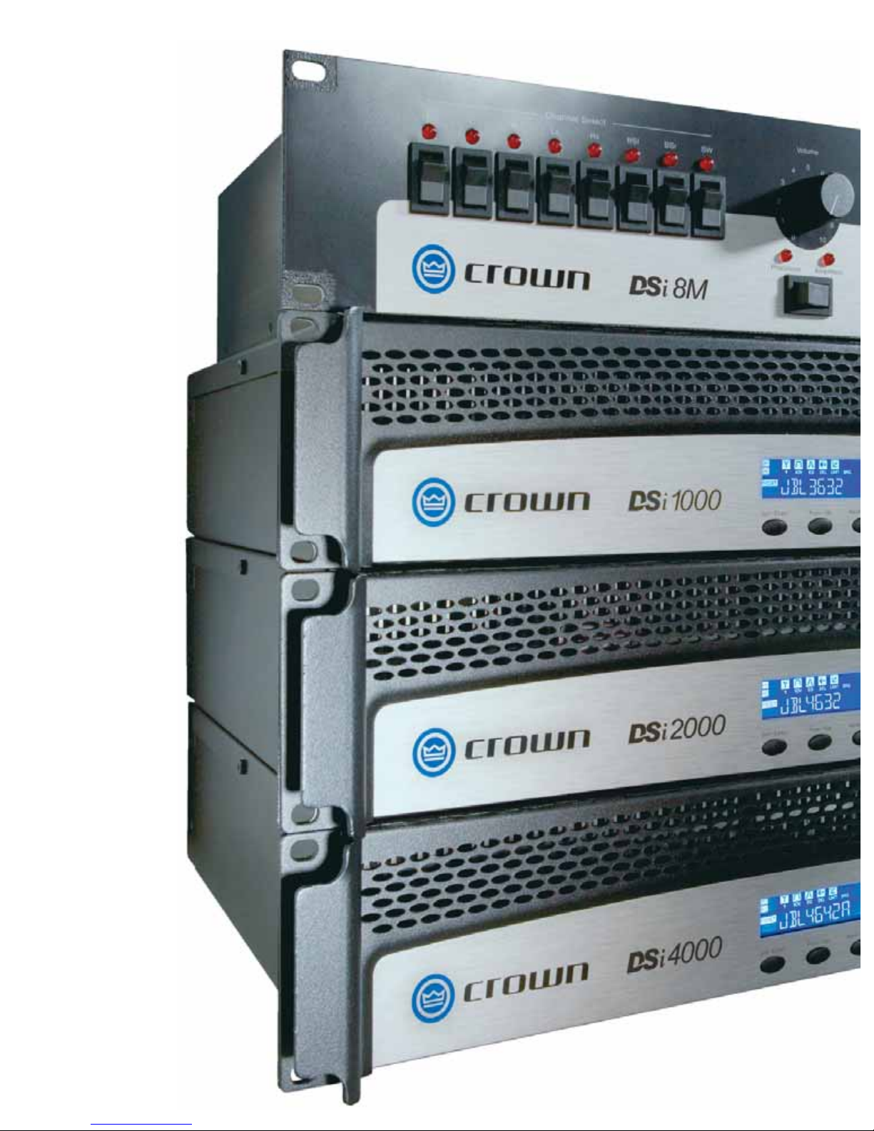
Page 59
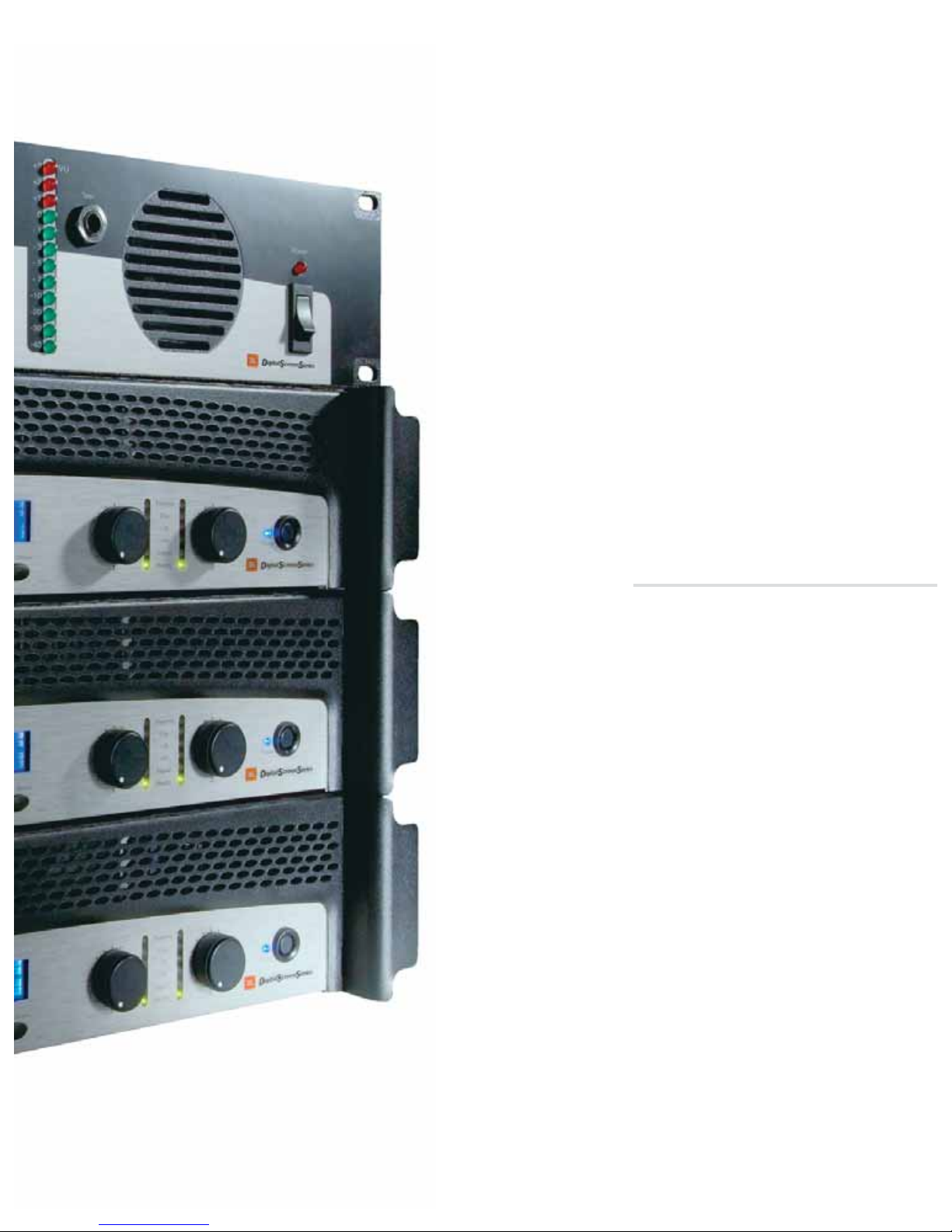
CINEMA
DSi Series
CTs 2-Channel Series
CTs Multi-Channel Series
XLS Series
DBC Network Bridge
Page 60
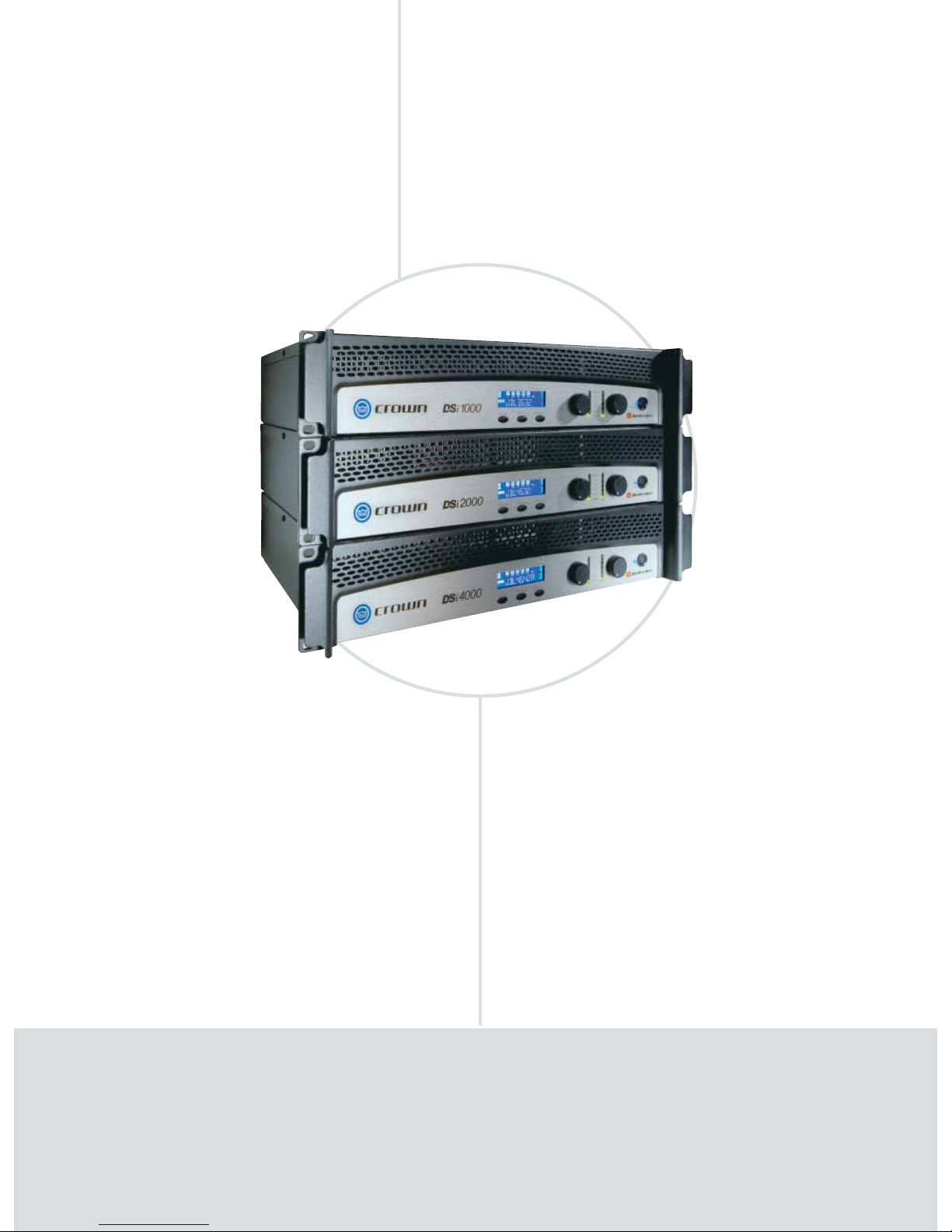
AMPLIFIERS CINEMA
DSi Series: 2/4/8 Ohm
DSi 1000, DSi 2000, DSi 4000
One-Touch
Performance
FEATURES
Intuitive front-panel LCD screen, automatic presets for popular JBL cinema
speaker systems for quick, easy confi guration.
Onboard digital signal processing includes crossovers, EQ fi lters, delay, and
output limiting.
Computer connectivity via USB allows fast setup and confi guration with
HiQnet™ System Architect® software.
Rear-panel HD-15 connector provides easy input/output connectivity
between DSi amplifi ers and new DSi-8M System Monitor.
Barrier strip outputs, removable Phoenix-style input.
All models are THX®-approved.
•
•
•
•
•
•
POWER OUTPUT
2-ohm Dual 4-ohm Dual 8-ohm Dual 4-ohm 8-ohm
Models (per channel) (per channel) (per channel) Bridge Bridge
DSi 1000 700W** 475W* 275W* 1,400W** 950W*
DSi 2000 1,000W** 800W* 475W* 2,000W** 1,600W*
DSi 4000 1,600W** 1,200W* 650W* 3,200W** 2,400W*
*1 kHz power with 0.5% THD. **With 1% THD.
Page 61

CINEMA
• 61
www.crownaudio.com
T
he Crown® DSi Series of power amplifiers provides onboard digital signal processing
including crossovers, EQ filters, delay and output limiting. A rear panel HD-15 connector provides easy input/output connectivity between DSi amplifiers and the new DSi-8M
System Monitor. The intuitive front panel LCD screen guides installers through a setup process—featuring presets for the industry-standard JBL cinema loudspeaker systems—to make
confi guration quick and easy. At the touch of a button, Crown’s DSi cinema amplifi ers deliver
perfectly matched performance with each award-winning JBL ScreenArray
®
system, making
this the ultimate cinema solution.
SPECIFICATIONS
Performance
Voltage Gain at 1kHz, 8 ohm rated output:
DSi 1000: 26 dB.
DSi 2000: 26 dB.
DSi 4000: 26 dB.
Frequency Response: +0/–1 dB from 20 Hz to 20
kHz at 1 watt into 4 ohms.
Load Impedance: Safe with all types of loads.
Rated for 2 to 8 ohms in Stereo mode, 4 to 16
ohms in Bridge-Mono mode.
Sensitivity:
At 8 ohm rated output:
DSi 1000: 1.4V.
DSi 2000: 1.4V.
DSi 4000: 1.4V.
At 4 ohm rated output:
DSi 1000: 1.3V.
DSi 2000: 1.2V.
DSi 4000: 1.3V.
At 2 ohm rated output:
DSi 1000: 1.1V.
DSi 2000: 1.0V.
DSi 4000: 1.0V.
Signal to Noise Ratio (below rated 8-ohm power
at 1 kHz): 100 dB (A weighted).
Damping Factor: Better than 500 from 20 Hz to
400 Hz.
Crosstalk: > 70 dB below rated power, 20 Hz to 1
kHz, A-weighted.
Input Stage: Input is electronically balanced and
employs precision 1% resistors.
Input Impedance (nominal): 20 k ohms, balanced;
10 k ohms, unbalanced.
Maximum Input Signal: +22 dBu typical.
AC Line Voltage and Frequency Configurations
Available: 100V, 120V, 220-240V, 50/60 Hz.
AC Line Current:
DSi 1000: 11.56A.
DSi 2000: 11.93A.
DSi 4000: 11.75A.
At Idle: Draws no more than 45 watts.
Operating Temperature: 0° C to 40° C at 95%
relative humidity (non-condensing).
DSP Section
Input EQ: 6 parametric fi lters per channel with
adjustable Q, ±15 dB boost/cut. Also adjustable
high and low shelving fi lters. This 8-fi lter EQ
section can be bypassed.
Crossover Filters: Highpass and lowpass
per channel. Butterworth 6/12/18/24 dB per
octave, Linkwitz-Riley 24/48 dB per octave. Also
includes ±15 dB bandpass gain and polarity
control.
Output EQ: 8 parametric fi lters per channel with
adjustable Q, ±15 dB boost/cut. This 8-fi lter EQ
section can NOT be bypassed. Filters are enabled
individually.
Output Limiter: Prevents clipping and protects
loudspeakers. Choice of –3, –6, or –12 dB
threshold per channel.
Delay: Up to 50 msec total delay per channel.
Presets: 20 presets. One is “DSP OFF.” Fifteen
are factory-set for JBL Cinema systems. Four
are user-defi nable.
Front Panel Controls and Indicators
Level: Detented rotary level control, one per chan-
nel.
Power Switch: On/off switch applies AC power to
the amplifier.
Sel/Prev/Next Buttons: Three buttons near the
LCD screen are used to access menu items and
front panel lockout.
LCD Screen: Backlit liquid crystal display shows
speaker presets and signal processing.
Signal Indicator: Green LED, one per channel,
illuminates when a very low-level signal is present
at input.
–10 Indicator: Green LED flashes when output
signal exceeds –10 dB below clip.
–20 Indicator: Green LED flashes when output
signal level exceeds –20 dB below clip.
Ready Indicator: Green LED, one per channel,
illuminates when the amplifier is ready to produce
audio.
Clip Indicator: Red LED, one per channel, turns on
at the threshold of audible distortion.
Temp Indicator: Red LED, one per channel, illuminates under excessive temperature conditions.
Power Indicator: Blue LED illuminates when the
amplifier has been turned on and has power.
Back Panel Controls and Connectors
AC Line Connector: NEMA 5-15P (15A).
Input Connector: Two 3-pin removable Phoenix-
type connectors each accept a balanced line-level
input signal.
Output Connectors: 4-position barrier strip with
connectors for dual loudspeakers or bridge-mono
loudspeaker.
HiQnet USB Connector: Type B, connects to a
HiQnet network.
HD-15 Connector: For cinema I/O compatibility
with DSi-8M System Monitor.
Protection
DSi-Series amplifiers are protected against shorted,
open or mismatched loads; overloaded power
supplies; excessive temperature; chain destruction
phenomena; excessive output current, and input
overload damage. They also protect loudspeakers
from input/output DC, large or dangerous DC offsets and turn-on/turn-off transients
Construction
Chassis: Steel.
Cooling
Proportional speed fan with front-to-rear airflow.
Dimensions
EIA Standard 19-in. (48.3-cm) rack mount width
(EIA RS-310-B), 3.5 in. (8.9 cm) high and 12.25 in.
(31.11 cm) deep behind mounting surface.
Weight
Net Weight: 19 lb (8.6 kg).
Shipping Weight: 22 lb (10.0 kg) .
Regulatory Certifications
Other Applications
Note: All measurements apply to all models of CDi
Series amplifiers in stereo mode with 8-ohm loads and
an input sensitivity of 26 dB gain, 1 kHz at rated power
unless other otherwise specified. Specifications for
units supplied outside the U.S.A. may vary slightly at
different AC voltages and frequencies.
Page 62
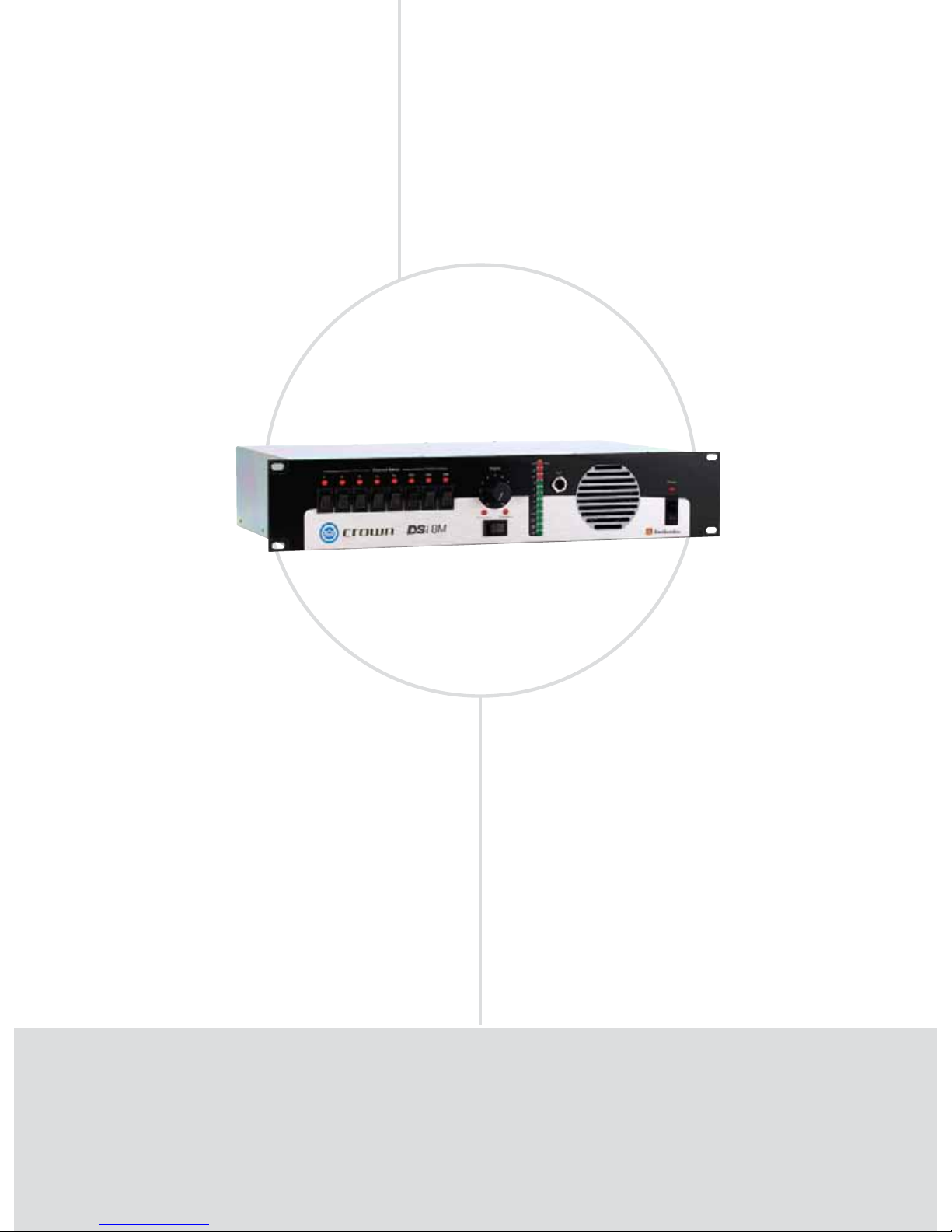
AMPLIFIERS CINEMA
DSi-8M: Convenient Monitoring
DSi-8M
Performance
Monitor
FEATURES
Compact 2-rack unit.
8 channels for monitoring processor or amplifi er inputs.
All inputs and outputs are balanced to interface with new cinema processors.
No level jumps when switching between processor and amplifi ers.
25-pin D-sub connectors, plus removable terminal blocks and HD-15 for
quick, hassle-free connections.
Designed to work with bi-amplifi ed sound systems to monitor the high- and
low-frequency outputs from the left, center and right channels.
•
•
•
•
•
•
Page 63

CINEMA
• 63
www.crownaudio.com
SPECIFICATIONS
Performance
Input Impedance (processor inputs): 10 kilohms.
Input Impedance (power amplifier inputs): > 50
kilohms.
Power Requirements: 100-240VAC, 50-60 Hz,
32 watts.
Front Panel Controls and Indicators
Channel Select Buttons and LEDs: Eight push-
button switches, one for each input channel.
Pressing a button monitors the signal from that
channel, and lights the corresponding LED. Any
combination of eight channels can be selected.
Volume Control: Rotary potentiometer with knob
controls the volume of the internal or external
speaker. Has no effect on the VU Bargraph Meter
display.
Processor/Amplifier Selector Switch and LEDs:
Push-button switch with corresponding LEDs
selects inputs from cinema processor or power
amplifiers for monitoring.
VU Bargraph Meter: 12-segment meter displays
input level of selected channels from –40 VU to
+3 VU. May be calibrated by the rear panel trim
adjustment. Operates independently of the Volume
Control.
Test Jack: 1/4-inch phone jack lets the user monitor the audio output of the DSi-8M. Inserting a
mono or stereo 1/4-inch phone plug here disables
the internal speaker and routes the audio output to
the Test Jack.
Internal Speaker: For convenient monitoring at the
monitor panel.
Power Switch and Power LED: Rocker switch
turns power on or off. LED illuminates when power
is on.
Back Panel Controls and Connectors
IEC AC Power Receptacle: Connects to an IEC AC
power cord.
Amplifier Outputs Connector 1: 10-pin removable
terminal block connects to the power amplifier
speaker outputs for the Ls, Rs, Bsl, Bsr and Sw
channels.
Amplifier Outputs Connector 2: 10-pin removable
terminal block connects to the power amplifier
speaker output for the Lh, Ll, Ch, Cl, Rh and Rl
channels.
Amplifier Level Control: Trim pot adjusts the level
of the input signals from the power amplifiers.
Processor Level: Trim pot adjusts the level of the
input signals from the processor.
HD-15 Connector 1: For cinema I/O compatibility.
Connects to Ls/Rs amplifier.
HD-15 Connector 2: Connects to Bsl/Bsr amplifier.
HD-15 Connector 3: Connects to Rl/Rh amplifier.
HD-15 Connector 4: Connects to Sw amplifier.
HD-15 Connector 5: Connects to Ll/Lh amplifier.
HD-15 Connector 6: Connects to Cl/Ch amplifier.
Optional Input Connector: 25-pin D-sub connector
connects to the EX output of the processor.
Bargraph Level: Trim pot adjusts the sensitivity of
the front-panel VU Bargraph Meter.
Main Input Connector: 25-pin D-sub connector
connects to the main outputs of the processor.
“EX” Selector Switch: 8-position DIP switch. Turn
on switches 1-4 if system is without EX. Turn on
switches 5-8 if system is with EX. This routes the
correct Ls/Rs inputs to the DSi-8M circuitry.
Construction
Chassis: Steel.
Dimensions
EIA Standard 19-inch (48.3-cm) rack mount width
(EIA RS-310-B), 3.5 inches (8.9 cm) high and
9.625 inches (24.4 cm) deep behind front mounting surface.
Weight
Net Weight: 10 lb 2 oz (4.63 kg).
Shipping Weight: 16 lb (7.26 kg).
Regulatory Certifications
T
he Crown® DSi-8M is a projection booth monitor designed to work with bi-amplifi ed cinema
systems using the Crown DSi Series amplifi ers. All controls necessary for daily operation of
the DSi-8M are easily accessible on the front panel. 8-channel monitoring allows you to monitor either the processor or the power amplifi er’s outputs: L, C, R, Ls, Rs, Bsl, Bsr, and Sub in
any combination. Input levels from the processor and power amplifi er can be adjusted independently. There are no huge level jumps when switching between processor and power amplifi ers.
The bargraph display can be calibrated to the reference level for your theater. The projectionist
can see auditorium levels instantly.
Page 64
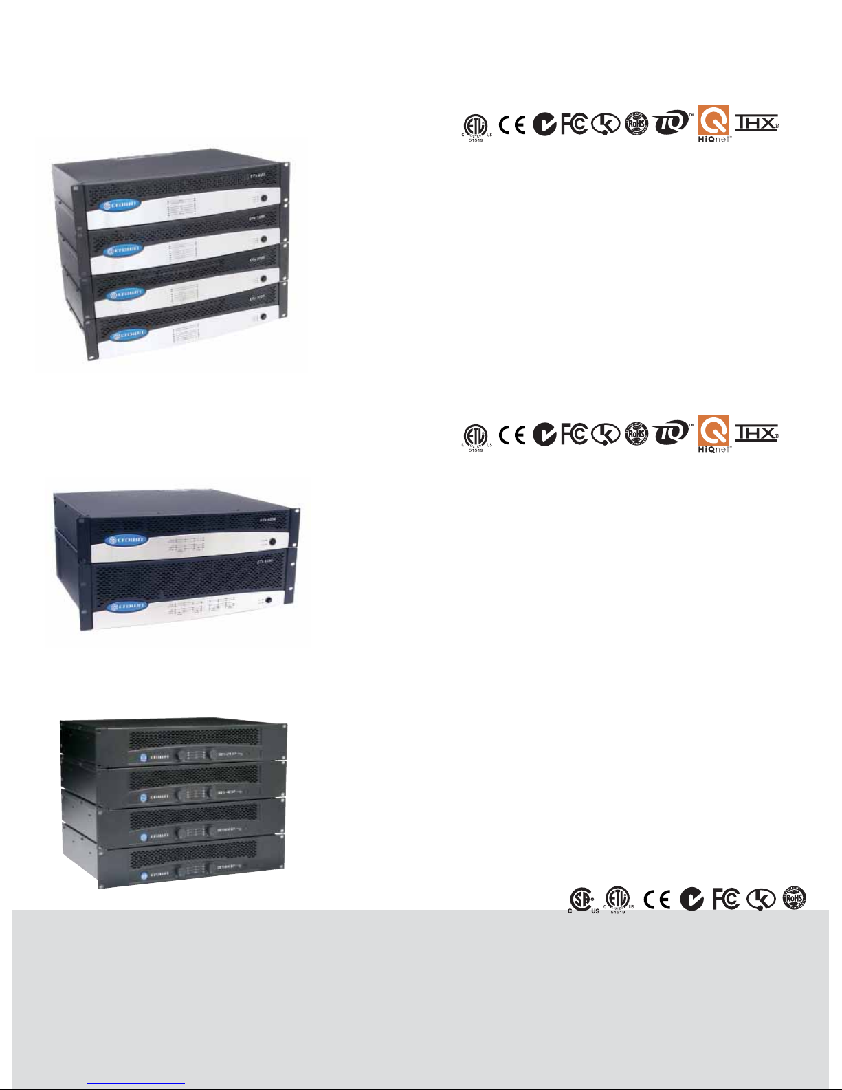
AMPLIFIERS CINEMA
Other Cinema Products
CTs
Multi-Channel
POWER OUTPUT*
All channels driven All channel pairs driven
Models 4-ohm Dual 8-ohm Dual 70V Dual 8-ohm Bridge
CTs 4200 260W 180W 220W** 520W
CTs 8200 200W 160W 200W** 400W
*Maximum average power in watts at 1kHz at 0.1% THD.
**Constant Voltage full-bandwidth power ratings support 100 Hz to 20 kHz due to automatic
high-pass fi lters.
XLS Series
POWER OUTPUT*
4-ohm Dual 8-ohm Dual 8-ohm
Model
(per channel) (per channel) Bridge
XLS 202 300W 200W 600W
XLS 402 450W 300W 900W
XLS 602 600W 380W 1,200W
XLS 802 800W 500W 1,600W
XLS 5000 1,800W 1,100W 3,200W
*Maximum average power in watts at 0.5% THD, 1 kHz.
CTs 2-Channel
FEATURES
Housed in a rugged, all-steel 2U chassis (3U in
XLS 5000).
Effi cient forced-air fan prevents excessive thermal buildup.
Electronically balanced XLR inputs; touchproof
binding post and Speakon outputs.
Precision detented level controls, power switch,
and four LEDs, which indicate clip for each
channel, power and fault conditions.
•
•
•
•
FEATURES
High power density: Four-channel model in a 2U
chassis, eight-channel model in a 3U chassis.
New Crown Switching Power Supply for lighter
weight.
Selectable “Constant-Voltage” or low-impedance (4/8 ohm) operation per channel-pair.
•
•
•
FEATURES
High power density. All two channel models in
a 2U chassis.
New Crown Switching Power Supply for lighter
weight.
•
•
Selectable “Constant-Voltage” or lowimpedance operation per channel.
100V direct outputs on all models.
Fully PIP2™-compatible.
•
•
•
100V direct outputs.
New “FIT” (Fault Isolation Topology) circuitry
isolates fault conditions without affecting neighboring channels.
Accept VCA-MC accessory modules.
•
•
•
Note: For more information about the products featured in this section, please refer to the following Crown
sections: CTs 2-Channel, CTs Multi-Channel, XLS Series.
POWER OUTPUT*
2-ohm Dual 4-ohm Dual 70V Dual 4-ohm
Models (per channel) (per channel) (per channel) Bridge
CTs 600 150W 300W 300W 300W
CTs 1200 250W 600W 600W 500W
CTs 2000 1,000W 1,000W 1,000W 2,000W
CTs 3000 1,500W 1,500W 1,500W 3,000W
*Maximum average power in watts at rated THD, 20 Hz - 20 kHz.
XLS 5000
only
except
XLS 5000
except
XLS 5000
Page 65
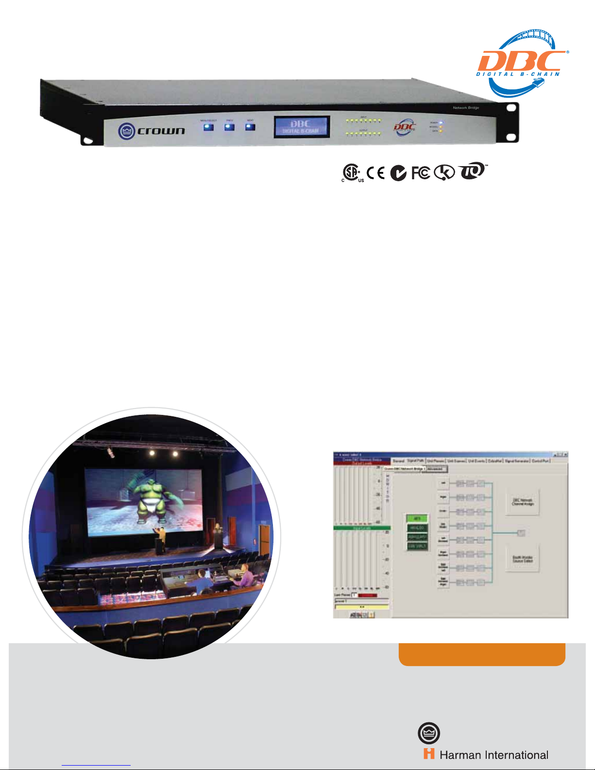
CINEMA
• 65
www.crownaudio.com
CINEMA DBC NETWORK BRIDGE
DBC® Network Bridge
All-Digital Cinema Solution
A
t the heart of a Digital B-ChainTM system, the Crown DBC® Network
Bridge allows you to distribute multiple channels of digital audio over
standard fast Ethernet hardware and cabling for use in traditional, e-cinema
and d-cinema applications.
The DBC Network Bridge accepts standard analog and/or AES digital audio
and CobraNet™ digital channels from other Cinema processors (Dolby®,
DTS®), Cinema Servers, or Alternative Content Media Players; and bridges
them to a Crown DBC network.
This network is Crown’s proprietary “Single-Click” solution that provides
system control, monitoring, and digital audio transport. The DBC network
(fed by the DBC Network Bridge) distributes the digital audio and systemwide control protocol to Crown amplifiers. The DBC Network Bridge also
provides the necessary system equalization, which is stored and recalled
via a series of presets for use in both feature film and alternative content
programming.
Accepts 8 inputs (7.1 surround)
via one of the following formats:
Analog AES/EBU CobraNet™.
Selectable mic or line auxiliary
analog XLR inputs for alternative
content.
Primary and Secondary 100 Mb
Ethernet “Single-Click” connection for DBC network.
Front-panel LCD display and control functions of internal presets
and system setup.
Full 32-channel CobraNet™ digital
audio transmit/receive capability.
Enhanced matrix mixer capable
of full 8x32 crosspoint matrix
mixing.
24-bit/48 kHz converters.
Studio-grade DSP with multiple
fi lter banks for each channel (up
to 256 fi lters).
•
•
•
•
•
•
•
•
32 presets, 32 scenes, and 32
events can be stored, labeled, and
recalled.
Analog monitoring of cinema
processor inputs, pre-amp, or
post-amp signals.
Multiple-function control port for
third-party automation/control.
Internal clock/calendar for scheduling events.
Auto leveling functions for
dynamic volume control of auditoriums or lobby.
Ambient leveling functions for
maintaining maximum signal-tonoise ratio.
Three-year, no-fault, fully transferable warranty.
•
•
•
•
•
•
•
FEATURES
DBC Network Bridge control screen.
Digital Circus, Raleigh, North Carolina, USA.
C
rown Cinema Systems employ quality Crown professional amplifiers along with optional amplifier
accessories for the best in cinema sound. Crown’s Digital B-Chain system, which provides the first alldigital cinema solution, employs Crown’s CTs Series amplifiers, IQ Networking amplifier modules,
and Crown’s DBC® Network Bridge for the first all-digital cinema solution.
Other Cinema Products
Page 66
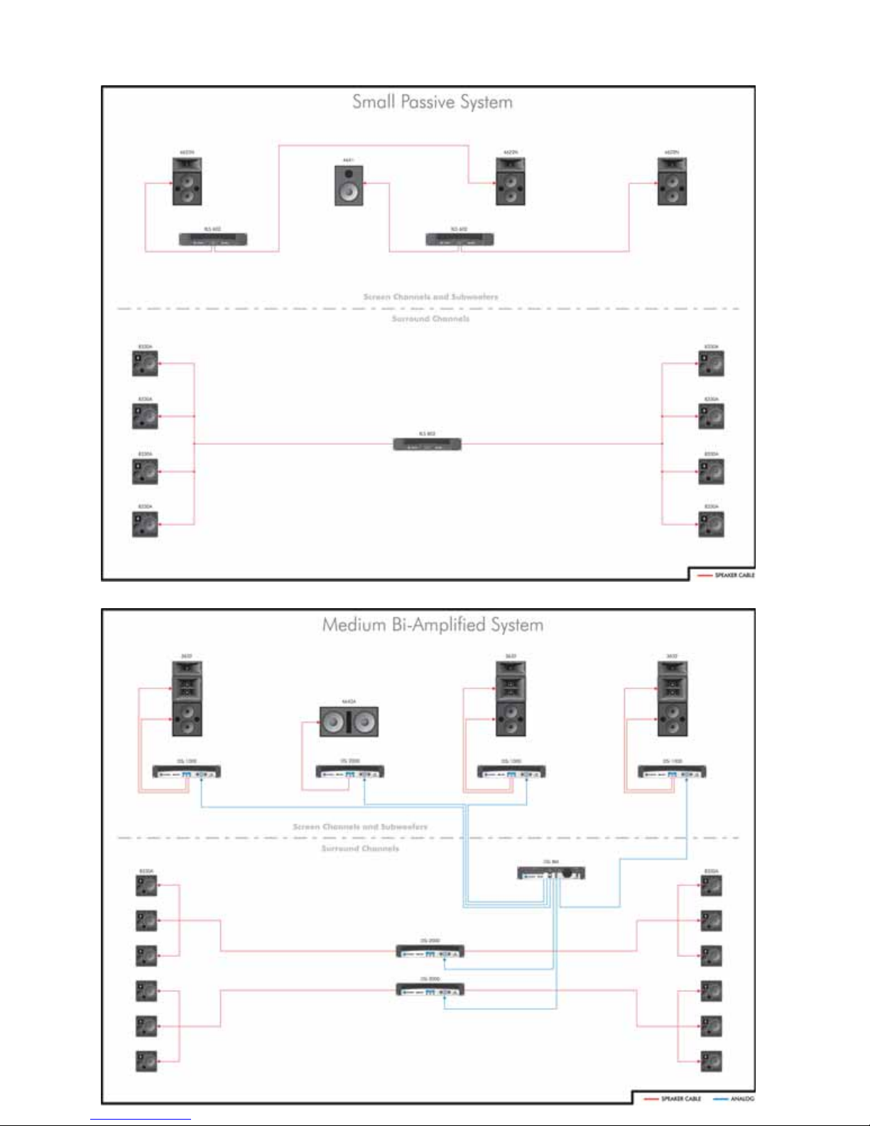
AMPLIFIERS CINEMA
Product Applications
Page 67
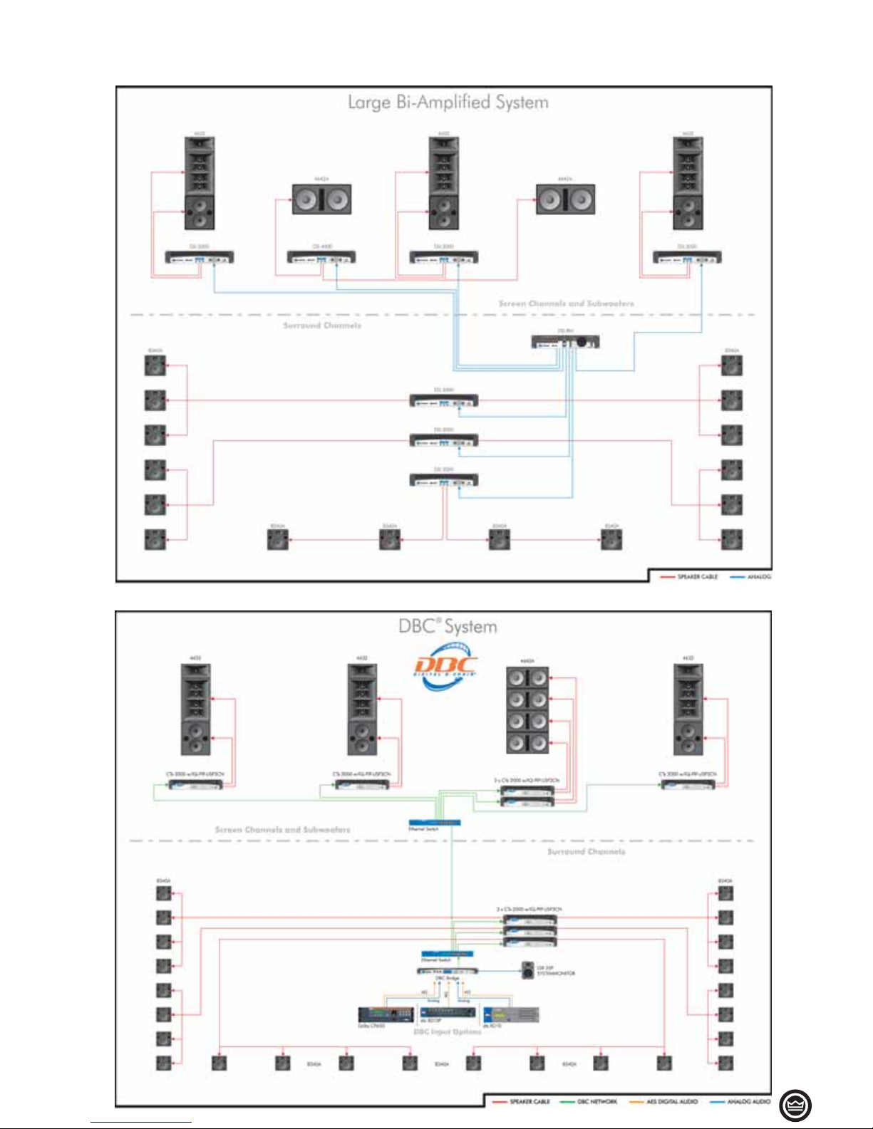
• 67
AMPLIFIERS CINEMA
Product Applications
Page 68
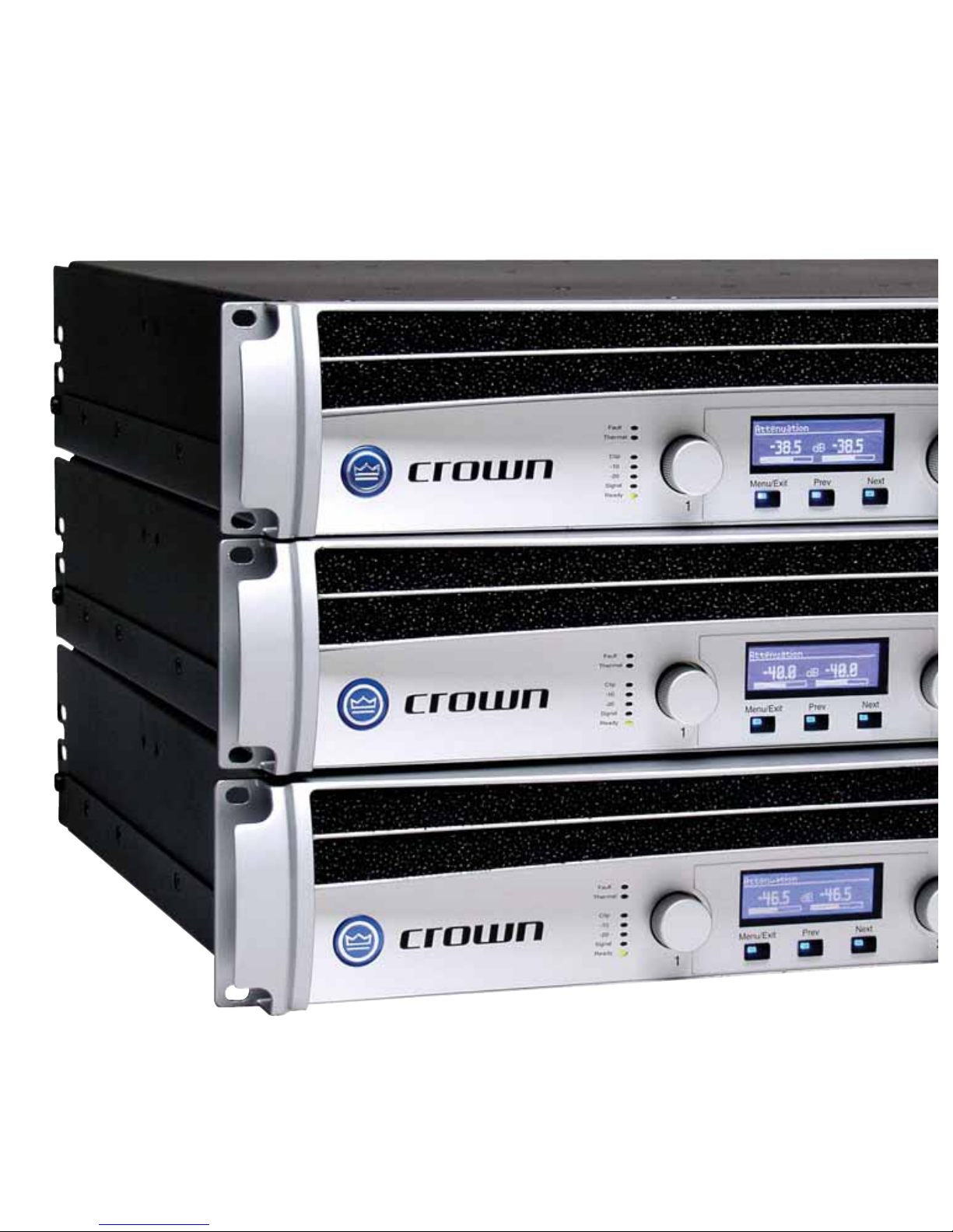
Page 69
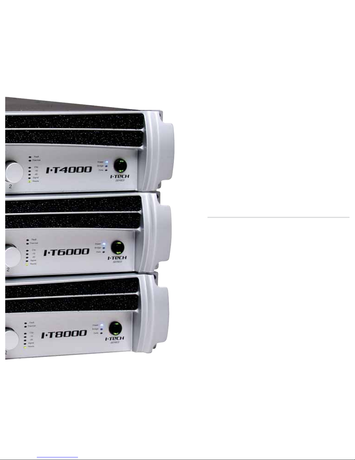
NETWORKED PRODUCTS
HiQnet™ Software
IQ® Software
PIPs
Accessories
Page 70
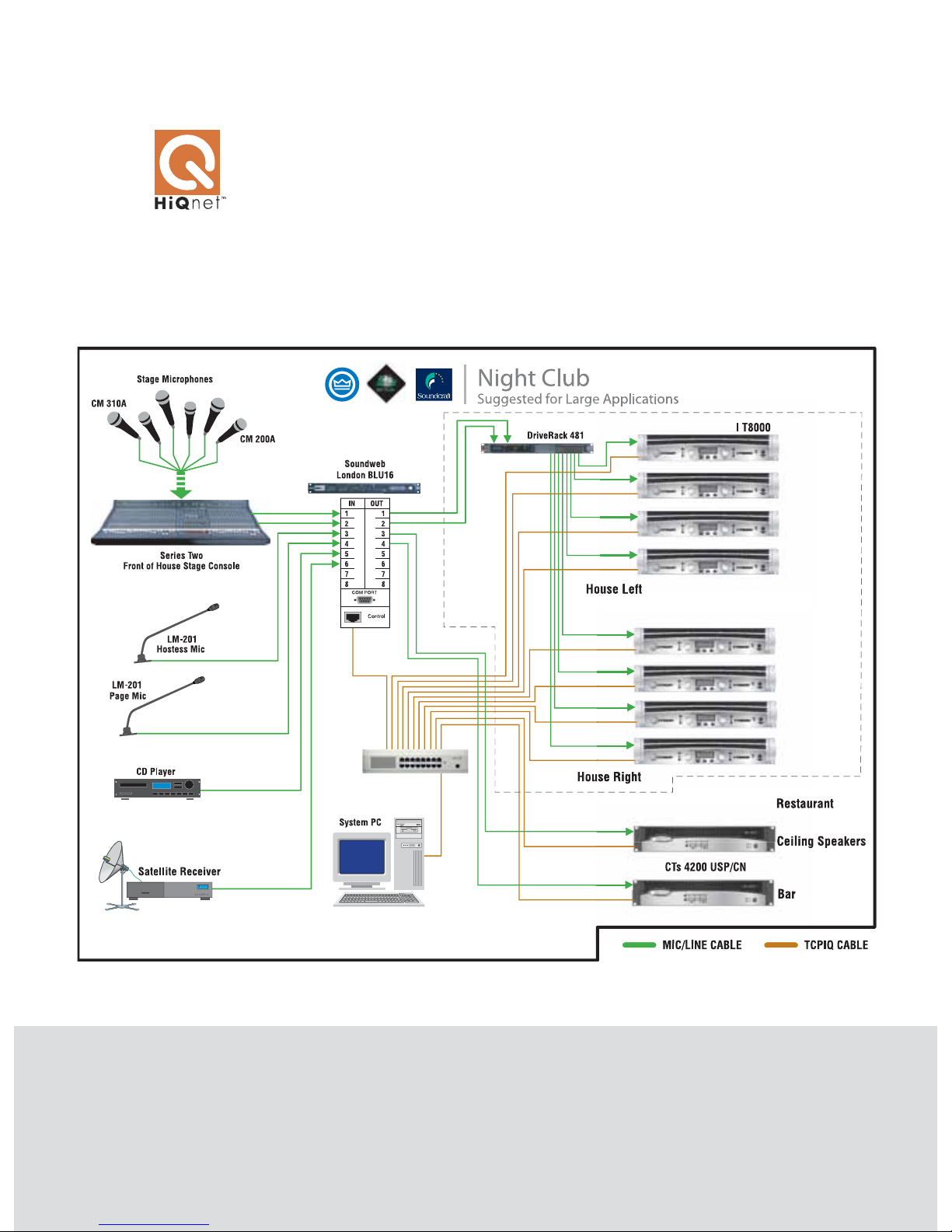
NETWORKED PRODUCTS HARMAN PRO HiQnet SOFTWARE
H
arman Pro System Architect is a fully-fea-
tured HiQnet™ software application that provides a seamless, easy-to-use interface for all the
devices in the signal path—from microphones to
speakers. Built using a modular software design,
Connect. Configure. Control.
System Architect takes full advantage of the
knowledge and expertise of each audio company
within the Harman Pro group. Product control
panel modules and plug-ins are developed
by each company for the products they have
designed, while comprehensive control of the
entire audio system is managed by the System
Architect core module. This allows expertise for
product operation and control to be maintained
for each product type, while system-wide functions like signal routing, event logging, and
venue-wide preset configuration and recall are
standardized for all operations and products.
The System Architect core module also provides global operation of audio network services such as local and remote monitoring,
streaming audio management, event logging,
and more.
For the individual devices, System Architect
provides access to extensive configuration,
monitoring and control functions through a
single, intuitive interface. From wireless microphone receiver setup to speaker tuning via
digital speaker presets, System Architect puts
you in control of your setup and configuration.
Components status during operation, such as
Page 71
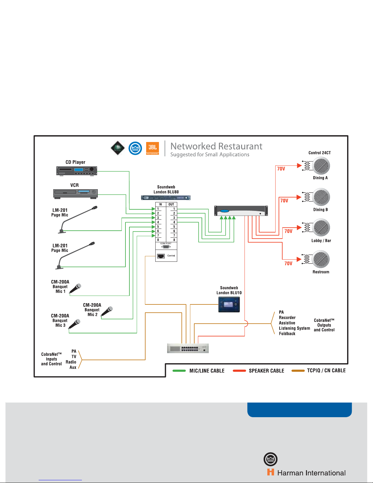
NETWORKED PRODUCTS
• 71
www.crownaudio.com
CTs 4200 USP/CN
amplifier loads, signal routes and processing, are
also easily monitored from a single control station. And when it's time to reconfigure, System
Architect can quickly update device routing and
settings, amplifier configurations and speaker
tunings.
User control and configuration also reaches new
levels with System Architect. The intuitive software interface provides easy customization of
window sets and control-panel design, as well as
a full-screen-mode option, for user touchscreen
PC control. BLU-10 touchscreen wall controllers
from the Soundweb London system and opti-
mized operation for tablet PC provide additional
tools for creation of user-control interfaces. Once
configured, system-wide parameters and presets
from any connected device can be placed easily
onto the same window to create single-screen,
custom control panels, eliminating the need for
complex programming of third-party control
devices.
System Architect offers:
Microphone control: wireless microphone
receiver setup; microphone status on a single
screen.
•
Signal control: monitor and control signal
routing and processing; multiple user signal
routing groups and customizable control and
monitor panels simplify operation; global
update of device routing and settings.
Amplifi er control: load monitoring, output
protection and limiting, error reporting.
Speaker control: remote access via the network to digital speaker presets.
PLUS: system-wide control via customized control panels for any attached device.
•
•
•
Page 72
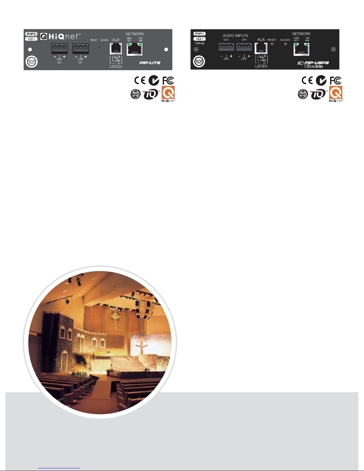
PIP LITE
SmartAmp Automation for Networked Audio
NETWORKED PRODUCTS PIPS
PIP USP3
Digital Signal Processing for Networked Audio
T
he Crown PIP USP3 is a 3rd generation DSP-based PIP (Programmable
Input Processor) input module for PIP2 compatible amplifiers.* It connects the amplifier to a 100 Mb Ethernet network allowing it to be remotely
controlled and monitored. This module connects to the audio control/monitor network using standard 100 Mb Ethernet hardware (switches, Network
Interface Cards, and cables).
The USP3’s SHARC DSP processor gives the user an enormous amount of
digital signal processing. Audio routing, faders, meters, polarity & mute,
input compressors, filters, delays, multimode output limiters, error reporting, and load monitoring are all available. A built-in noise generator and sinewave generator provide noise masking and test capabilities. The enhanced
AUX port capability allows the user to interface with the amplifier to provide
external manual control and monitoring.
Offering crisp, clear sound and the widest dynamic range possible with full
24-bit converters, the PIP USP3 provides unprecedented power and flexibility in one compact—and very affordable—module.
100 Mb Ethernet single-plug
solution for networked control
and monitoring.
Listen Bus amplifi er output monitor (through CobraNet™).
24-bit conversion with 32-bit,
fl oating point DSP processing.
64 assignable fi lters with 9 different fi lter types including all-pass
fi lters.
Over 2 seconds of delay available
per channel.
•
•
•
•
•
Input compressors and output
limiters for each channel.
Dual, uncorrelated noise generators for noise masking.
Sine-wave noise generator.
Load supervision.
Full error reporting.
Firmware upgrades via the net-
work.
10 user-selectable presets.
Reliable FLASH memory backup
of all parameters.
•
•
•
•
•
•
•
•
A Programmable Input Processor
with system networking capabilities (connects via 100 Mb
Ethernet).
Remote control and monitoring
of PIP2-compatible Crown amplifi ers as well as some PIP1 -compatible amplifi ers.*
•
•
Can be connected to the same
network used to transmit
CobraNet™ audio.
Implements SmartAmp features:
input compressors, multimode
output limiters, error reporting
and load monitoring.
AUX connector confi gurable for
AUX input, AUX output, or Listen
Bus.
•
•
•
T
he Crown PIP LITE is a PIP (Programmable Input Processor) input
module for PIP2 compatible amplifiers. The PIP-LITE connects to an
audio control network via 100 Mb Ethernet. The audio path in the PIP LITE
is processed totally in the analog domain. The SmartAmp™ feature set offers
a range of automation functions which provide greater control over amplifier
operation and helps to save both time and money.
ANALOG AUDIO INPUTS
TCP / IQ
* Please refer to the module compatibility chart at the end of the System Solutions
section.
FEATURES
FEATURES
* Please refer to the module compatibility chart at the end of the System Solutions
section.
Page 73
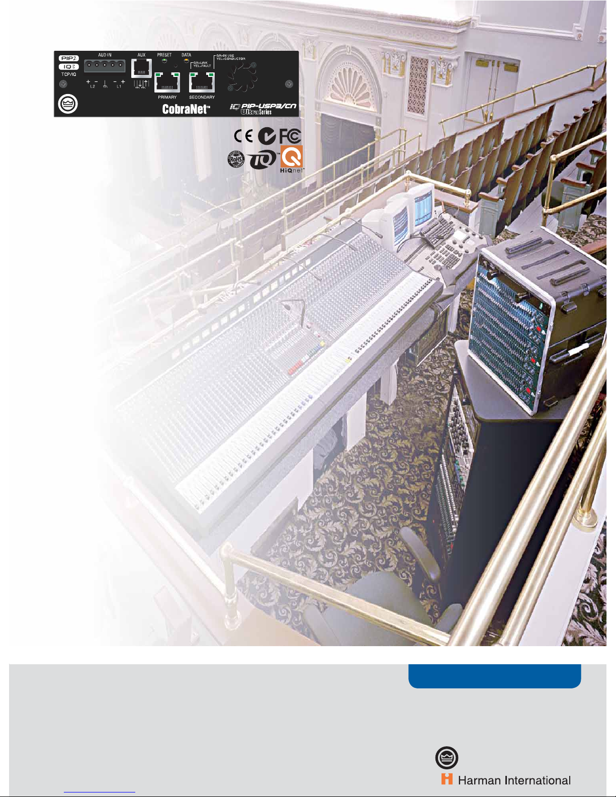
NETWORKED PRODUCTS
• 73
www.crownaudio.com
PIP USP3/CN
SmartAmp Automation for TCP/IQ
T
he Crown PIP-USP3/CN is a 3rd generation DSP-based PIP™
(Programmable Input Processor) input module for PIP2 compatible
amplifiers.* It connects the amplifier to a 100 Mb Ethernet network allowing it to be remotely controlled and monitored. In addition, the USP3/CN
allows the transport of real-time digital audio via CobraNet™ over the same
Ethernet network.
The USP3/CN connects to the audio control/monitor network using standard
100 Mb Ethernet hardware (switches, Network Interface Cards, and cables).
CobraNet™ audio is available over the same 100 Mb Ethernet network, providing a simple to install, single plug solution for audio distribution, control,
and monitoring.
The USP3/CN’s SHARC DSP processor gives the user an enormous amount
of digital signal processing. Audio routing, faders, meters, polarity & mute,
input compressors, filters, delays, multimode output limiters, error reporting, and load monitoring are all available. A built-in noise generator and sinewave generator provide noise masking and test capabilities. The enhanced
AUX port capability allows the user to interface with the amplifier to provide
external manual control and monitoring.
100 Mb Ethernet single-plug
solution for both CobraNet™
audio and networked control and
monitoring.
Analog audio inputs allow audio
input to the CobraNet™ network,
CobraNet™ audio redundancy, or
a hardwire emergency override of
CobraNet™ audio.
Listen Bus amplifi er output monitor via CobraNet™.
24 bit digital to analog conversion
with 32 bit, fl oating point DSP
processing.
64 assignable fi lters with 9 different fi lter types including all-pass
fi lters.
•
•
•
•
•
Over 2 seconds of delay available
per channel.
Input compressors and output
limiters for each channel.
Dual, uncorrelated noise generators for noise masking.
Sine-wave generator.
Load supervision.
Full error reporting.
Firmware upgrades via the
network.
10 user selectable presets.
Reliable FLASH memory backup
of all parameters.
•
•
•
•
•
•
•
•
•
* Please refer to the module compatibility chart at the end of the System Solutions
section.
FEATURES
Page 74
Page 75
ACCESSORIES &
REFERENCE
Accessories
Amplifier Feature Comparison
Amplifier Specifications
Module Compatibility
Crown Amplifier Warranty
Page 76
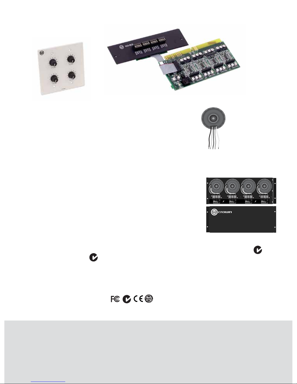
ACCESSORIES & REFERENCE ACCESSORIES
TP–170V
2 INPUTS: COM
OUTPUTS: COM 70V
70V50V40V
100V
3 INPUTS: COM
OUTPUTS: COM 70V
70V50V40V
100V
4 INPUTS: COM
OUTPUTS: COM 70V
70V50V40V
100V
1 INPUTS: COM
OUTPUTS: COM 70V
70V50V40V
100V
TP-170V Constant-Voltage
Transformer Panel
The Crown® TP-170V is a rack-mountable panel
with four autoformers to provide impedance matching between amplifier outputs and “constant voltage” loudspeakers. This unit allows amplifiers without direct 70V or 100V output capability to drive
distributed speaker systems designed to operate
at those voltages. The TP-170V is constructed of
sturdy steel, and hinged on one side to allow easy
access to the inside connections.
Accessories
T-170V Constant-Voltage
Transformer
The Crown T-170V is a single
autoformer that provides impedance matching between an amplifier output and “constant voltage”
loudspeakers. It allows amplifiers
without direct 70V or 100V out-
put capability to drive distributed speaker systems
designed to operate at those voltages.
VCA-MC4A & VCA-MC8
FEATURES
Independent remote level control for each channel.
4-pin removable Phoenix-style barrier connectors provide the +10VDC control voltage,
ground, and control lines for two amplifi er
channels.
Optional wall-mount level control panels for use
with VCA modules: 1-VCAP and 4-VCAP.
Remote Level Control
The Crown VCA-MC4A and VCA-MC8 are optional
level-control modules for the Crown CTs multi-channel power amplifiers. The VCA-MC4A is for the CTs
4200, and the VCA-MC8 is for the CTs 8200.
A VCA-MC module provides independent remote
level control for each channel. 4-pin removable
Phoenix-style barrier connectors provide the
+10VDC control voltage, ground, and control lines
for two amplifier channels. Thus, the 4-channel
CTs 4200 uses two connectors; the 8-channel CTs
8200 uses four connectors. Crown CTs 4200 and
8200 amplifiers can be supplied with a VCA-MC
module already factory-installed, or your choice of
MC modules can be easily added to the amplifier
by any authorized Crown Service Center.
Choosing the Right Module
To order accessory modules for your amplifier, please
refer to the model tag (located on the back panel of the
amplifier) for your amplifier’s specific model number.
Then refer to the information below to select the correct
accessory for your requirements.
CTs4200: VCA-MC4 or IQ-MC4
CTs 4200A: VCA-MC4A or IQ-MC4A
CTs 8200 or CTs 8200A: VCA-MC8 or IQ-MC8
•
•
•
Regulatory Certifications
For all CTs Multi-Channel Amp Accessories:
1-VCAP & 4-VCAP
FEATURES
1-VCAP provides remote volume control for one
or more CTs amplifi er channels.
Fits into a 1-gang electrical box.
4-VCAP provides remote volume control for
four or more CTs amplifi er channels.
Fits into a 2-gang electrical box.
Wall-Mount Controllers
Crown VCAP panels are wall-mounted panels
with potentiometers that provide remote control
of the volume of Crown CTs amplifier channels
via a VCA-MC4 or VCA-MC8 module installed in
the amplifier. Two models are available: 1-VCAP
and 4-VCAP.
1-VCAP: Used in conjunction with a VCA-MC
module, this is a 1-gang panel with one potentiometer that provides remote volume control
for one or more CTs amplifier channels. The
potentiometer on the panel is wired directly
to the VCA connectors on the VCA-MC.
4-VCAP: This is a 2-gang panel with four potentiometers that provide remote volume control
for four or more CTs amplifier channels. The
potentiometers on the panel are wired directly
to the VCA connectors on the VCA-MC.
•
•
•
•
Page 77
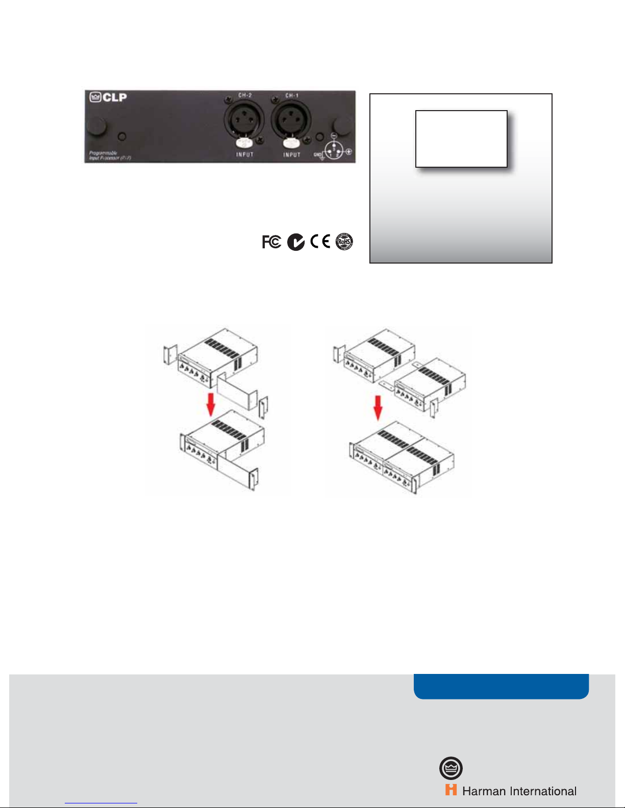
ACCESSORIES
• 77
www.crownaudio.com
P.I.P.-CLP
The P.I.P.-C.L.P. is designed to detect and prevent overload. The same error
detecting circuit that is used to signal the IOC indicator is used to activate this
error-driven compressor. It is not a typical signal-driven compressor but a
circuit to prevent an overload. It can yield up to 13 dB of additional signal safety
margin without noticeable program change.
cya
(cover your amp)
3PLUS3 3+3 Extended Warranty
Crown’s No-Fault, 3+3 Extended Warranty package extends the terms of your original full warranty for an additional three years, thus covering
years four through six. Available for Crown
amplifiers only.
ACCESSORIES & REFERENCE ACCESSORIES
IST Isolation Transformer
The Crown IST is a 600-ohm to 600-ohm isolation
transformer used for telephone connectivity. It is
designed to be used with Commercial Audio models
135MA and 160MA mixer-amplifiers.
Accessories
RM1 Rack-Mounting Kit
The Crown RM1 is a single-unit rack-mounting kit.
It is designed to be used with Commercial Audio
models 135MA and 160MA mixer-amplifiers.
RM2 Rack-Mounting Kit
The Crown RM2 is a dual-unit rack-mounting kit.
It is designed to be used with Commercial Audio
models 135MA and 160MA mixer-amplifiers.
S-COVER Security Cover Bulk Pack
The Crown S-COVER is a 10-pack of security covers. It is designed to be used with Commercial Audio
models 135MA and 160MA mixer-amplifiers.
Commercial Audio Accessories
Page 78
ACCESSORIES & REFERENCE AMPLIFIER FEATURE COMPARISON CHART
1. T-170V autoformer, TP-170V autoformer panel optional
accessories.
2. Fault Isolation Topology, Hi/low Z output mode switch.
3. MC modules and VCA modules option allow remote volume
control.
Amplifier Feature Comparison
4. Bridge-mono option, input-sensitivity option.
5. Both have Variable Impedance (VZ); MA5002VZ has compressor.
6 MA5002VZ has screw terminals and banana jacks.
MA3600VZ,
MA5002VZ
MA-i CTs 2-Ch. CTs multi-
Ch.
Protection systems
ODEP/JTS
XX
600/1200 only
X
Thermal Level Control (TLC)
XX
Automatic high-pass fi lter
X
Switchable high-pass fi lter
X
Low-pass fi lter (ultrasonic/RFI protect.)
X
Power circuit breaker
MA5002VZ only
XX
Proportional-speed fans
XXXX
Automatic current and voltage limiting
Quad Mute
Convection cooled (no fan)
Advanced Features
Class I (BCA)
X
2000/3000 only
only
Switching power supply
XXX
Grounded Bridge
X
AB+B
600/1200 only
X
Bridge Mode Indicator
XXX
Y input switch
X
Input Sensitivity Switch
XXX
IOC
X
Standby mode
2000/3000 only
Precision detented level controls
XXX
Other (specify)
51012
Options
Onboard DSP
HiQnet compatible
X
CobraNet
Input modules
Output modules
Level Control shaft lock
PIP compatible
X
PIP2 compatible
X
Other (specify)
3
Input
XLR
X
1/4-inch
X
Combo
Screw terminals
XX
Phoenix
Output
Speakon
X
Binding posts
MA3600VZ only
X
Screw terminals
6XX
Other (specify)
Page 79
REFERENCE
• 79
www.crownaudio.com
7. Onboard IQ networking via TCP/IQ or CobraNet™,
AES/EBU digital input, onboard DSP, pushbutton
presets, global power supply with PFC, LCD control
screen shows status/diagnostics.
8. Two male XLR passive analog loop through. XLR
active/re-clocked AES/EBU digital loop through.
CTs multi
CobraNet
D XLS I-Tech DSi CDi XTi 2402 180A,
280A
1160A
X XXXXX
X
X
XX X
X XXXXX
XX X
X
X X
X
X XXXX
X
XXX
XX
XXXX
XX
XX
X
X XXXXX
2
headphone jk
79
X XXXX
X XXXX
XX
XX X
X
X
34
XX XXX
X
X
X
XX X
XX
XX XX
XXX XX X
8
ACCESSORIES & REFERENCE AMPLIFIER FEATURE COMPARISON CHART
9. Rear-panel HD-15 connector provides easy I/O connectivity between DSi amps and DSi-8M System Monitor.
10. Volume Control LED ring shows control position, fl ashes
when amp is muted, can be converted to level meter.
Amplifi er monitoring and control via System Architect
®
.
Page 80
REFERENCE AMPLIFIER SPECIFICATIONS
Amplifier Specifications
Amplifi ers
Dual Power Per Channel
1
Mono Power
2
Dimensions Weight Comments
CCA 180A
80W-4
19 x 4.1 x 13.9” 21 lb 1 input, 1 output ch.
CCA 280A
80W-4 or 70V/100V
19 x 4.1 x 13.9” 25.3 lb 2 inputs, 2 output ch.
CCA 1160A
160W-4 or 70V/100V
19 x 4.1 x 13.9” 25.3 lb 1 input, 1 output ch.
CCA 660A
60W-4 or 70V/100V
19 x 4.1 x 13.9” 30.3 lb 6 input ch., 6 output ch.
CDi 1000
700W-2 , 500W-4 , 275W-8
1400W-4 , 1000W-8
19 x 3.5 x 12.25” 19 lb Low-Z or 70V, switch-mode power
supply, integrated DSP with
speaker presets
CDi 2000
1000W-2 , 800W-4 , 475W-8 2000W-4 , 1600W-8
19 x 3.5 x 12.25” 19 lb
CDi 4000
1600W-2 , 1200W-4 , 650W-8
3200W-4
19 x 3.5 x 12.25” 19 lb
CTs 600
150W-2 , 300W-4 , 300W-8 ,
300W-1 X, 300W-70V
300W-4 , 600W-8 , 600W-16 ,
600W-140V
19 X 3.5 X 14.25” 22 lb 13 ozSwitching power supply; high
power densitiy; direct constant-
voltage operation, independently
selectable input sensitivity per
channel; JTS protects output
tran sistors in CTs 600/1200; AB&B
topology in CTs 600/1200; Class I
(BCA) topology in CTs 2000/3000,
PIP compatible
CTs 1200
250W-2 , 600W-4 , 600W-8 ,
300W-16 , 600W-70V
500W-4 1200W-8 , 1200W-16 ,
1200W-140V
19 X 3.5 X 14.25” 23 lb 6
oz
CTs 2000
1000W-2 , 1000W-4 , 1000W-8 ,
625W-16 , 1000W-70V, 1000W-
100V
2000W-4 , 2000W-8 , 2000W-16 ,
2000W-140V, 2000W-200V
19 X 3.5 X 14.25” 27 lb
CTs 3000
1500W-2 , 1500W-4 , 1250W-8 ,
625W-16 , 1500W-70V, 1500W-
100V
3000W-4 , 3000W-8 , 2500W-16 ,
3000W-100V, 3000W-200V
19 X 3.5 X 14.25” 27 lb 11
oz
CTs 4200
260W-4 , 200W-8 , 220W-70V 520W-8 , 400W-16 , 220W-100V
19 X 3.5 X 16.25” 27 lb 8 ozMultichannel amps; switching poer
supply; JTS protects output
tran sistors, high power densitiy;
con stant voltage or low Z or each
ch. pair; Fault Isolaton Topology
iso lates faults; MC modules for
remote control
CTs 8200
200W-4 , 160W-8 , 200W-70V 400W-8 , 320W-16 , 200W-100V
19 X 5.25 X 16.25” 36 lb 6
oz
D-45
35W-4 , 25W-8 70W-8
19 x 1.75 x 9” 8 lb AB+B circuitry; Power/Signal/IOC
indicators, headphone jack; Dual/
Bridge-Mono; Neutrik combo input
connectors; detented front level
controls, convection cooling
D-75A
55W-4 , 40W-8 110W-8
19 x 1.75 x 9” 9 lb
DSi 1000
700W-2 , 500W-4 , 275W-8 1400W-4 , 1000W-8
19 x 3.5 x 12.15” 17 lb Presets for JBL cinema speakers,
front-panel LCD screen, onboard
DSP, HiQnet System Architect
compatible, HD-15 connectors
interface with DSi-8M System
Monitor, switch-mode universal
power supply, barrier strip out puts
and Phoenix input
DSi 2000
1000W-2 , 800W-4 , 475W-8 2000W-4 , 1600W-8
19 x 3.5 x 12.15” 17 lb
DSi 4000
1600W-2 , 1200W-4 , 650W-8
3200W-4 , 2400W-8
19 x 3.5 x 12.15” 17 lb
I-T4000
1800W-2 , 2000W-4 , 1240W-
3600W-4 , 4000W-8
19 x 3.5 x 16” 20 lb Amazing power in a 2U lightweight
chassis, global power supply with
PFC, on baord DSP, bult-in
net working to IQ System or HiQnet
via TCP/IQ or CobraNet™, LCD
control screen shows amplifi er
status and diagnostics, pushbutton
DSP pre sets for various
I-T6000
2500W-2 , 3000W-4 , 1500W-8
5000W-4 , 6000W-8
19 x 3.5 x 16” 28 lb
I-T8000
3500W-2 , 4000W-4 , 2100W-8
7000W-4 , 8000W-8
19 x 3.5 x 16” 28 lb
MA-2402
1050W-2 , 800W-4 , 520W-8 2070W-4 , 1585W-8
19 x 3.5 x 16” 51 lb 12
oz
Grounded Bridge circuitry; ODEP,
IOC/SPI indicators; separate power
supplies; Dual, Bridge-Mono and
Par allel-mono modes; balanced XLR
input connectors; front-panel level
controls; grond lift switch; forced-air
cooling; PIP compatible
MA-3600VZ
1800W-2 , 1565W-4 , 1120W-8 3505W-4 , 3140W-8
19 x 3.5 x 16” 55 lb 4
oz
3-mode VZ power supply for
maxi mum power matching; see
MA2402 features
MA-5002VZ
2500W-2 , 2000W-4 , 1300W-8 5000W-4 , 4000W-8
19 x 5.25 x 16” 77 lb 13
oz
MA-5000i
1800W-2 , 2000W-4 , 1250W-8 3600W-4 , 4000W-8
19 x 3.5 x 16.2” 28 lb Unparalleled sonic accuracy and
detail; patented, cutting-edge
Class-I circuitry; more power with
less waste; rugged construction;
global power supply works
anywhere; Ethernet networking lets
system operators monitor and
control the amp from any location
MA-9000i
2500W-2 , 3000W-4 , 1500W-8 5000W-4 , 6000W-8
19 x 3.5 x 16.2” 28 lb
MA-12000i
3500W-2 , 4000W-4 , 2100W-8 7000W-4 , 8000W-8
19 x 3.5 x 16.2” 28 lb
Page 81
REFERENCE
• 81
www.crownaudio.com
1. IQ-PIP LITE may be installed in older PIP1-compatible amplifi ers by using the USP2 Adapter Kit (functionality
slightly limited when using the Adapter Kit).
2. MA-5000VZ amplifi ers with serial numbers beginning with the prefi x A or B are PIP2 compatible. PIP2
compatible amplifi ers bear the PIP2 logo
on the rear.
3 . Analog PIPs include P.I.P.-CLP.
REFERENCE MODULE COMPATIBILITY
XLS 202
300W-4Ω, 200W-8Ω 600W-8Ω 19 x 3.5 x 15.2" 23 lb Rugged all-steel 2U chassis; effi-
cient cooling fan; electronically
balanced XLR inputs; touch-proof
binding post and Speakon
®
out-
puts; precision detented level con-
trols, clip/power/fault indicator
LEDs
XLS 402
450W-4Ω, 300W-8Ω 900W-8Ω 19 x 3.5 x 15.2" 25.7 lb
XLS 602
600W-4Ω, 380W-8Ω 1200W-8Ω 19 x 3.5 x 15.2" 29 lb
XLS 802
800W-4Ω, 500W-8Ω 1600W-8Ω 19 x 3.5 x 15.2" 35.5 lb
XLS 5000
2500W-2Ω, 1800W-4Ω, 1100W-8Ω
3200W-8Ω, 5000W−4Ω, 19 x 5.25 x 15.2" TBD
Xs500
750W-2Ω, 500W-4Ω, 400W-8Ω 1600W-4Ω, 1450W-8Ω 19 x 3.5 x 17" 28 lb
Rugged all-steel 2U chassis; efficient
cooling fan; XLR-1/4" combo and
Phoenix-style inputs; daisy-chain
XLR outputs; binding post outputs
and Speakon outputs; precision
detented level controls; LEDs for clip,
power, AC present, temperature and
fault conditions; microprocessor-
controlled protection system; ligh-
weight design
Xs700
900W-2Ω, 750W-4Ω, 450W-8Ω 1900W-4Ω, 1645W-8Ω 19 x 3.5 x 17" 28 lb
Xs900
1100W-2Ω, 900W-4Ω, 600W-8Ω
2500W-4Ω, 2100W-8Ω 19 x 3.5 x 17" 28 lb
Xs1200
1600W-2Ω, 1100W-4Ω, 650W-8Ω 2000W-4Ω, 2300W-8Ω 19 x 3.5 x 17" 28 lb
XTi 1000
700W-2Ω, 500W-4Ω, 275W-8Ω 1400W-4Ω, 1000W-8Ω 19 x 3.5 x 12.25" 18.5 lb Speaker presets with LCD front
panel display, onboard DSP, han-
dles a wide range of loads, switch-
mode universal power supply,
Speakon and binding posts out-
puts; XLR inputs and loop-thrus
XTi 2000
1000W-2Ω, 800W-4Ω, 475W-8Ω 2000W-4Ω, 1600W-8Ω 19 x 3.5 x 12.25" 18.5 lb
XTi 4000
1600W-2Ω, 1200W-4Ω, 650W-8Ω 3200W-4Ω, 2400W-8Ω 19 x 3.5 x 12.25" 18.5 lb
1. Guaranteed minimum power in Dual mode, both channels driven
2. Guaranteed minimum power in Bridge-Mono mode
Module Compatibility
Amplifier Specifications
AMPLIFIER ANALOG
PIPS
3
PIP-LITE PIP-USP3 PIP-USP3/CNVCA-MC4,
VCA-MC4A
VCA-MC8
CTs 600/
1200/2000/
3000
X X X
X0024 sTC
CTs 8200 X
MA02
Series
XXXX
MA 3600VZ X 1
MA 5000VZ X 2 2 2
MA 5002VZ X X X X
CCA, CDi,
D, DSi, IT,
MAi,
XLS and
XTi Series
Page 82

Crown Amplifier Warranty
USA AND CANADA
SUMMARY OF WARRANTY
Crown International, 1718 West Mishawaka Road, Elkhart, Indiana 46517-4095 U.S.A. warrants to you, the ORIGINAL PURCHASER and ANY SUBSEQUENT OWNER
of each NEW Crown product, for a period of three (3) years from the date of purchase by the original purchaser (the “warranty period”) that the new Crown product
is free of defects in materials and workmanship. We further warrant the new Crown product regardless of the reason for failure, except as excluded in this Warranty
Warranty is only valid within the country in which the product is purchased.
ITEMS EXCLUDED FROM THIS CROWN WARRANTY
This Crown Warranty is in effect only for failure of a new Crown product which occurred within the Warranty Period. It does not cover any product which
has been damaged because of any intentional misuse, accident, negligence, or loss which is covered under any of your insurance contracts. This Crown
Warranty also does not extend to the new Crown product if the serial number has been defaced, altered, or removed.
WHAT THE WARRANTOR WILL DO
We will remedy any defect, regardless of the reason for failure (except as excluded), by repair, replacement, or refund. We may not elect refund unless you
agree, or unless we are unable to provide replacement, and repair is not practical or cannot be timely made. If a refund is elected, then you must make the
defective or malfunctioning product available to us free and clear of all liens or other encumbrances. The refund will be equal to the actual purchase price,
not including interest, insurance, closing costs, and other finance charges less a reasonable depreciation on the product from the date of original purchase.
Warranty work can only be performed at our authorized service centers or at the factory. Warranty work for some products can only be performed at
our factory. We will remedy the defect and ship the product from the service center or our factory within a reasonable time after receipt of the defective
product at our authorized service center or our factory. All expenses in remedying the defect, including surface shipping costs in the United States, will
be borne by us. (You must bear the expense of shipping the product between any foreign country and the port of entry in the United States including the
return shipment, and all taxes, duties, and other customs fees for such foreign shipments.)
HOW TO OBTAIN WARRANTY SERVICE
You must notify us of your need for warranty service within the warranty period. All components must be shipped in a factory pack, which, if needed, may be
obtained from us free of charge. Corrective action will be taken within a reasonable time of the date of receipt of the defective product by us or our authorized service
center. If the repairs made by us or our authorized service center are not satisfactory, notify us or our authorized service center immediately.
DISCLAIMER OF CONSEQUENTIAL AND INCIDENTAL DAMAGES
YOU ARE NOT ENTITLED TO RECOVER FROM US ANY INCIDENTAL DAMAGES RESULTING FROM ANY DEFECT IN THE NEW CROWN PRODUCT. THIS INCLUDES
ANY DAMAGE TO ANOTHER PRODUCT OR PRODUCTS RESULTING FROM SUCH A DEFECT. SOME STATES DO NOT ALLOW THE EXCLUSION OR LIMITATIONS
OF INCIDENTAL OR CONSEQUENTIAL DAMAGES, SO THE ABOVE LIMITATION OR EXCLUSION MAY NOT APPLY TO YOU.
WARRANTY ALTERATIONS
No person has the authority to enlarge, amend, or modify this Crown Warranty. This Crown Warranty is not extended by the length of time which you are
deprived of the use of the new Crown product. Repairs and replacement parts provided under the terms of this Crown Warranty shall carry only the unexpired portion of this Crown Warranty.
DESIGN CHANGES
We reserve the right to change the design of any product from time to time without notice and with no obligation to make corresponding changes in products previously manufactured.
LEGAL REMEDIES OF PURCHASER
THIS CROWN WARRANTY GIVES YOU SPECIFIC LEGAL RIGHTS, YOU MAY ALSO HAVE OTHER RIGHTS WHICH VARY FROM STATE TO STATE. No action to
enforce this Crown Warranty shall be commenced after expiration of the warranty period.
THIS STATEMENT OF WARRANTY SUPERSEDES ANY OTHERS CONTAINED IN THIS MANUAL FOR CROWN PRODUCTS. 9/07
TRADEMARKS NOTICE: Crown, Crown Audio, Amcron, BCA, IQ, Differoid, DBC, IOC, IQ System, Macro-Tech, ODEP, P.I.P., and VZ are registered trademarks; Digital
B-Chain, Grounded Bridge, Power-Tech, PIP, PIP2, TCP/IQ, IQwic, SmartAmp, IQ2 and XTi are trademarks of Crown International.
Neutrik, Speakon, Windows, Dolby, DTS, HiQnet, CobraNet, ScreenArray, dbx, System Architect, Phoenix and JBL are used for information only and are the property of their
respective companies.
Crown Audio, Inc. reserves the right to make changes in specifications, software, or products without prior notice. Crown Audio, Inc. also assumes no responsibility
for any error in type or print reproduction of the features or specifications in this literature. The information provided in this manual was deemed accurate as of the
publication date. However, updates to this information may have occurred. To obtain the latest version of this manual, please visit the Crown website at www.crownaudio.com.
Some models may be exported under the name Amcron.
Page 83

REFERENCE
• 83
www.crownaudio.com
Crown Amplifier Warranty
WORLDWIDE EXCEPT USA & CANADA
SUMMARY OF WARRANTY
Crown International, 1718 West Mishawaka Road, Elkhart, Indiana 46517-4095 U.S.A. warrants to you, the ORIGINAL PURCHASER and ANY SUBSEQUENT OWNER
of each NEW Crown product, for a period of three (3) years from the date of purchase by the original purchaser (the “warranty period”) that the new Crown product is free of defects in materials and workmanship, and we further warrant the new Crown product regardless of the reason for failure, except as excluded in this
Warranty.
Warranty is only valid within the country in which the product is purchased.
1 Note: If your unit bears the name “Amcron,” please substitute it for the name “Crown” in this warranty.
ITEMS EXCLUDED FROM THIS CROWN WARRANTY
This Crown Warranty is in effect only for failure of a new Crown product which occurred within the Warranty Period. It does not cover any product which has been
damaged because of any intentional misuse, accident, negligence, or loss which is covered under any of your insurance contracts. This Crown Warranty also does
not extend to the new Crown product if the serial number has been defaced, altered, or removed.
WHAT THE WARRANTOR WILL DO
We will remedy any defect, regardless of the reason for failure (except as excluded), by repair, replacement, or refund. We may not elect refund unless you
agree, or unless we are unable to provide replacement, and repair is not practical or cannot be timely made. If a refund is elected, then you must make the
defective or malfunctioning product available to us free and clear of all liens or other encumbrances. The refund will be equal to the actual purchase price,
not including interest, insurance, closing costs, and other finance charges less a reasonable depreciation on the product from the date of original purchase.
Warranty work can only be performed at our authorized service centers. We will remedy the defect and ship the product from the service center within a
reasonable time after receipt of the defective product at our authorized service center.
HOW TO OBTAIN WARRANTY SERVICE
You must notify your local Crown importer of your need for warranty service within the warranty period. All components must be shipped in the original box.
Corrective action will be taken within a reasonable time of the date of receipt of the defective product by our authorized service center. If the repairs made by our
authorized service center are not satisfactory, notify our authorized service center immediately.
DISCLAIMER OF CONSEQUENTIAL AND INCIDENTAL DAMAGES
YOU ARE NOT ENTITLED TO RECOVER FROM US ANY INCIDENTAL DAMAGES RESULTING FROM ANY DEFECT IN THE NEW CROWN PRODUCT. THIS INCLUDES
ANY DAMAGE TO ANOTHER PRODUCT OR PRODUCTS RESULTING FROM SUCH A DEFECT.
WARRANTY ALTERATIONS
No person has the authority to enlarge, amend, or modify this Crown Warranty. This Crown Warranty is not extended by the length of time which you are
deprived of the use of the new Crown product. Repairs and replacement parts provided under the terms of this Crown Warranty shall carry only the unexpired portion of this Crown Warranty.
DESIGN CHANGES
We reserve the right to change the design of any product from time to time without notice and with no obligation to make corresponding changes in products previously manufactured.
LEGAL REMEDIES OF PURCHASER
No action to enforce this Crown Warranty shall be commenced after expiration of the warranty period.
THIS STATEMENT OF WARRANTY SUPERSEDES ANY OTHERS CONTAINED IN THIS MANUAL FOR CROWN PRODUCTS. 9/07
 Loading...