

Page 1
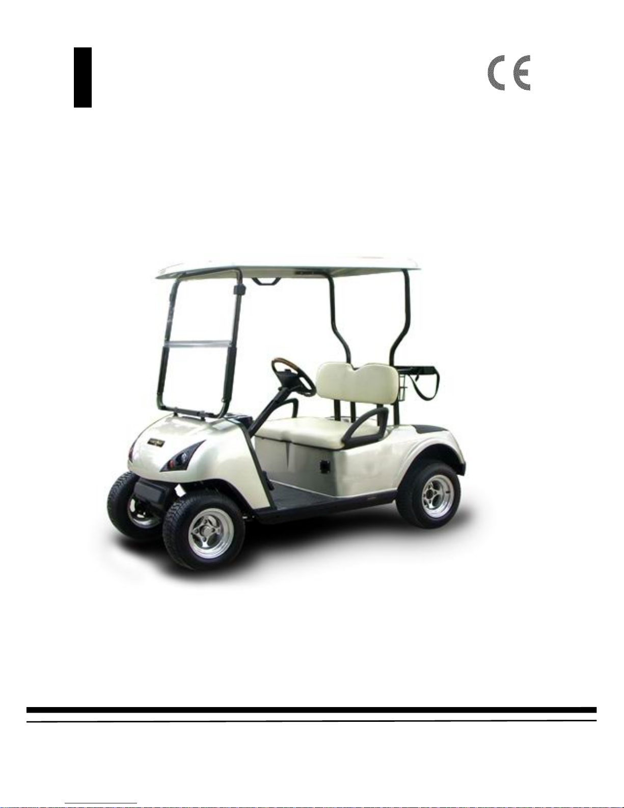
Owner’s Manual and
Service Guide
Original Instruction
Page 2

TABLE OF CONTENTS
SAFETY INFORMATION……………………………………………………...1- 7
OPERATION AND SERVICE INFORMATION……………………………..8-43
Before initial use………………………………………………………………………………….8
Key switch…………………………………………………………………………......................9
Direction selector, accelerator pedal……………………………………………….......................10
Combination brake and park brake pedal, horn, operating the vehicle…………………………..11
Regenerative braking……………………………………………………………………………..12
Diagnostic mode feature, starting and driving, start vehicle on a hill……………………………13
Coasting, sun top and windshield, vehicle cleaning and care……………………………………14
REPAIR
Lifting the vehicle………………………………………………………………………………..15
Wheels and tires………………………………………………………………………………….16
Wheel installation………………………………………………………………………………..17
Light bulb replacement…………………………………………………………………………..18
Service and maintenance…………………………………………………………………………19
Periodic service schedule………………………………………………………….......................20
Tire inspection……………………………………………………………………………………21
Brake……………………………………………………………………………………………..21
Rear axle………………………………………………………………………………………….23
Lubrication……………………………………………………………………………………….24
Hardware…………………………………………………………………………………………25
BA TTERIES AND CHARGING
Safety…………………………………………………………………………………………….26
Battery maintenance……………………………………………………………………………...27
Battery Replacement……………………………………………………………………………..30
Prolonged Storage………………………………………………………………………………..31
Battery charging………………………………………………………………………………….32
Troubleshooting………………………………………………………………………………….34
Hydrometer……………………………………………………………………............................34
Battery Maintenance ………….……………………………………………………....................36
Specific gravity testing…………………………………………………………………………..37
Open-circuit voltage test……………………………………………………………………...... 38
Charging, cleaning……………………………………………………………………………….40
Storage……………………………………………………………………………………………41
Battery terms explained…………………………………………………………………………..42
MAINTENANCEINFORMATION………………………………………......44-56
Troubleshooting………………………………………………………………………………….44
Front/Rear bridge, lubricate the wheel hub bearing, adjust the front
Page 3

wheel bearing…………………………………………………………………………………....45
Correct the toe-in, replace the front shock absorber, replace the front beam………………….. 46
Replace the front spring armor plate…………………………………………………….............47
Replace the wheel hub…………………………………………………………………………..48
Replace the wheel bearing assembly, Replace the rack ball joint, replace the claw…………….49
Replace the steering axle, Rear axle assembly…………………………………………………..50
Remove the shock absorber, Install the shock absorber, Remove the rear spring armor plate,
Assemble the rear spring armor plate, Rear axle maintenance, Check the lubricant level,
Disassemble and assemble of the transaxle………………………………………………………51
Disassemble and replace the oil seal, Install the axle…………………………………………….52
Check the brake pedal and connection…………………………………………………………...54
T est the brake function regularly, Check the wheel brake…………………………………..........55
SPECIFICATION……………………………………………………………....57-60
P ARTS AND ASSEMBLY PROCEDURE……………………………………61-65
Item identification………………………………………………………………………………..62
Assembly procedure……………………………………………………………………………..63
Page 4

SAFETY INFORMATION
Owner’s Manual and Service Guide
1
This manual has been designed to assist in maintaining the vehicle in accordance with procedures developed
by the manufacturer. Adherence to these procedures and troubleshooting tips will ensure the best possible
service from the product. To reduce the chance of personal injury or property damage, the following must by
carefully observed:
GENERAL
Good common sense and prudent driving practices do more to prevent accidents and injury than all of the
warnings and instructions combined. The manufacturer strongly suggests that all users and maintenance
personnel read this entire manual paying particular attention to the CAUTIONS and WARNINGS contained
there in.
Golf cart, Resort cart& Specialty products reserves the right to make design changes without obligation to
make these changes on units previously sold and the information contained in this manual is subject to
change without notice.
Golf cart, Resort cart& Specialty products is not liable for errors in this manual or for incidental or
consequential or consequential damages that result from the use of the material in this manual.
These vehicles are designed and manufactured for off-road use. Some communities may permit these vehicles
to be operated on their streets on a limited basis and in accordance with local ordinances.
With electric powered vehicles, be sure that all electrical accessories are grounded directly to the battery (-)
post. Never use the chassis or body as a ground connection.
Refer to GENERAL SPECIFICATIONS for vehicle seating capacity.
Never modify the vehicle in any way that will alter the weight distribution of the vehicle, decrease its
stability or increase the speed beyond the factory specification. Such modifications can cause serious
personal injury or death.
Vehicles that are capable of higher speeds must limit their speed to no more than the speed of other vehicles
when used in a golf course environment. Additionally, speed should be further moderated by the
environmental conditions, terrain and common sense.
GENERAL OPERATION
Always:
z Use the vehicle in a responsible manner and maintain the vehicle in safe operating condition.
z Read and observe all warnings and operation instruction labels affixed to the vehicle.
z Follow all safety rules established in the area where the vehicle is being operated..
Page 5

SAFETY INFORMATION
Owner’s Manual and Service Guide
2
z Reduce speed to compensate for poor terrain or conditions.
z Apply service brake to control speed on steep grades.
z Maintain adequate distance between vehicles.
z Reduce speed in wet areas.
z Use extreme caution when approaching sharp or blind turns.
z Use extreme caution when driving over loose terrain.
z Use extreme caution in areas where pedestrians are present.
MAINTENANCE
Always:
z Maintain the vehicle in accordance with the manufacturer’s periodic service schedule.
z Ensure that repairs are performed by those that are trained and qualified to do so.
z Follow the manufacturer’s maintenance procedures for the vehicle. Be sure to disable the vehicle before
performing any maintenance. Disabling includes removing the key from the key switch and removal of a
battery wire.
z Insulated any tools used within the battery area in order to prevent sparks or battery explosion caused by
shorting the battery terminals or associated wiring. Remove the batteries or cover exposed terminals
with an insulating material.
z Check the polarity of each battery terminal and be sure to rewire the batteries correctly.
z Use specified replacement parts. Never use replacement parts of lesser quality.
z Use recommended tools.
z Determine that tools and procedures not specifically recommended by the manufacturer will not
compromise the safety of personnel nor jeopardize the safe operation of the vehicle.
z Support the vehicle using wheel chocks and jack stands. Never get under a vehicle that is supported by a
jack. Lift the vehicle in accordance with the manufacturer’s instructions.
z Maintain the vehicle in an area away from exposed flame or persons who are smoking.
z Be aware that a vehicle that is not performing as designed is a potential hazard and must not be operated.
z Test drive the vehicle after any repairs or maintenance. All tests must be conducted in a safe area that is
free of both vehicular and pedestrian traffic.
z Replace damaged or missing warning, caution or information labels.
z Keep complete records of the maintenance history of the vehicle.
Use extreme caution and, if unsure as to the potential for injury, refer the repair or maintenance to a qualified
mechanic.
PART II
FOR THE USER
4 GENERAL SAFETY PRACTICES
4.1 Introduction
Like other machines, golf cart can cause injury if improperly used or maintained. Part II contains
broad safety practices applicable to golf cart operations. Before operation, the user shall establish
such additional specific safety practices as may reasonably be required for safe operation.
4.2 Nameplates, Markings, Capacity, and Modifications
Page 6

SAFETY INFORMATION
Owner’s Manual and Service Guide
3
4.2.1 The user shall maintain in a legible condition all nameplates, warnings and instructions which are
supplied by the manufacturer.
4.2.2 The user shall not perform any modification or addition which affects capacity or safe operation, or
make any change not in accordance with the owner’s manual without the manufacturer’s prior written
authorization. Where authorized modifications have been made, the user shall ensure that capacity,
operation, warning and maintenance instruction plates, tags or decals are changed accordingly.
4.3 Changing and Charging Storage Batteries for Electric Personnel and Burden Carriers
4.3.1 The user shall require battery changing and charging facilities and procedures to be in accordance
with appropriate paragraphs of ANSI/NFPA 505.
4.3.2 The user shall periodically inspect facilities and review procedures to be certain that appropriate
paragraphs of ANSI/NFPA 505, are strictly complied with and shall familiarize carrier operators with
it.
5 OPERATING SAFETY RULES AND PRACTICES
5.1 General
5.1.1 Safeguard the pedestrians at all times. Do not drive Cart in a manner that would endanger anyone.
5.1.2 Riding on the Cart by persons other than the operator is authorized only on personnel seat provided by
the manufacturer.
5.1.3 When a cart is to be left unattended, stop it, apply the parking brake, stop the engine or turn off power,
turn off the control or ignition circuit, and remove the key if provided. Block the wheels if machine is
on an incline.
5.1.4 Use only approved Cart in hazardous locations, as defined in the appropriate safety standards.
5.1.5 Operators shall not add to, or modify, the Cart.
5.2 Traveling
5.2.1 Observe all traffic regulations, including authorized speed limits. Under normal traffic conditions keep
to the right. Maintain a safe distance, based on speed of travel, from a vehicle ahead; and keep the Cart
under control at all times.
5.2.2 Do not pass another vehicle traveling in the same direction at intersections, blind spots, or at other
dangerous locations.
5.2.3 Keep a clear view of the path of travel, observe other traffic and personnel, and maintain a safe
clearance.
5.2.4 Slow down or stop, as conditions dictate, and activate the sound-producing warning device at cross
aisles and when visibility is obstructed at other locations.
5.2.5 Ascend or descend grades slowly.
5.2.6 Under all travel conditions the Cart shall be operated at a speed that will permit it to be brought to a
stop in a safe manner.
5.2.7 Do not indulge in dangerous activities, such as stunt driving or horseplay.
5.2.8 Avoid running over loose objects, potholes, and bumps.
5.2.9 To negotiate turns, reduce speed to improve stability, then turn hand steering wheel or tiller in a smooth,
sweeping motion.
5.3 Loading
5.3.3 At the beginning of each shift during which the Cart will be used, the operator shall check the Cart
condition and inspect the tires, warning devices, lights, battery, speed and directional controllers,
brakes, and steering mechanism. If the Cart is found to be in need of repair or in any way unsafe, the
Page 7

SAFETY INFORMATION
Owner’s Manual and Service Guide
4
matter shall be reported immediately to the design ated auth orit y an d the Cart shall no t b e operat ed unt il
it has been restored to sage operating condition.
5.3.4 Do not make repairs or adjustments unless specifically authorized to do so.
5.3.5 Do not operate a Cart with a leak in the battery.
5.3.6 Do not use open flames for checking electrolyte level in storage battery.
6 MAINTENANCE PRACTICES
6.1 Introduction
6.1.1 Carriers may become hazardous if maintenance is neglected. Therefore, maintenance facilities
trained personnel, and procedures shall be providing such facilities may be on or off the premises.
6.2 Maintenance Procedures
6.2.1 Maintenance and inspection of all Cart shall be performed in conformance with the manufacturer’s
recommendations and the following practices.
(a) A scheduled preventive maintenance, lubrication, and inspection system shall be followed.
(b) Only qualified and authorized personnel shall be permitted to maintain, repair, adjust, and
inspect carriers.
(c) Block chassis before working underneath it.
(d) Operation to check performance of the cart shall be conducted in an authorized area where safe
clearance exists.
(e) Before commencing operation of the cart, follow the manufacturer’s instructions and
recommended procedures.
(f) Avoid fire hazards and have fire protection equipment present in the work area. Do not use an
open flame to check level or leakage of battery electrolyte.
(g) Properly ventilate the work area.
(h) Brakes, steering mechanisms, speed and directional control mechanisms, warning devices, lights,
governors, guards, and safety devices shall be inspected regularly and maintained in a safe
operating condition .
(i) Special cart or devices designed and approved for hazardous area operation shall be inspected to
ensure that maintenance preserves the original approved safe operating features.
(j) Carriers shall be kept in a clean condition to minimize fire hazards and facilitate detection of
loose or defective parts.
(k) Modification and additions which affect capacity and safe machine operation shall not be
performed by the customer or user without manufacturer’s prior written authorization; where
authorized modifications have been made, the user shall ensure that capacity, operation, warning,
and maintenance instruction plates, tags, or decals are changed accordingly.
(l) Care shall be taken to ensure that all replacement parts are interchangeable with the original parts
and of a quality at least equal to that provided in the original equipment.
PART II
MAINTENANCE AND OPERA TIONS
5. GENERAL SAFETY PRACTICES
Introduction
Like other machines, golf cars can cause injury if improperly used or maintained. This section contains broad
safety practices recommended for safe golf car operations. Before operation, the controlling party should
establish such additional specific safety practices as may be reasonably required for safe operations.
Page 8

SAFETY INFORMATION
Owner’s Manual and Service Guide
5
Experience has shown that golf cars which comply with the provisions stated in part II of this standard are
safe when properly operated in accordance with the safety and operation is enhanced when the golf cars are
operated within a specific set of operation instructions, safety rules and practices established to meet actual
operating terrain and conditions.
The safety information contained in part II is intended to provide the controlling party with basic safety
information and to encourage the controlling party to implement a golf car safety program.
It is suggested and recommended that Part II be reprinted in the golf car manufacturer’s operation and service
manuals to encourage safe operations and practices at the controlling party’s facility.
Safety Survey
The controlling party shall perform a safety survey periodically, and as conditions warrant to their premises,
to identify areas where golf cars should not be operated and to identify possible hazards.
Wet area and Loose Terrain or icy terrain
Wet grassy areas and loose terrain may cause a golf car to lose traction and may affect stability. Wet areas and
loose terrain shall be chained or roped off to prevent golf car operations or be identified by a suitable warning
not to operate golf cars in this area due to wet and loose terrain.
Extreme caution should be used when driving on wet or icy terrain. Wet grassy areas or ice may cause a golf
car to lose traction and may affect operator control. Wet or icy areas should be chained or roped off to
prevent golf car operations or be identified by a suitable warning to operators not to operate golf cars in that
area.
Sharp Turns, Blind Corners, Bridge Approaches
Sharp turns, blind spots, bridge approaches and other potentially hazardous areas shall be either chained or
roped off to prevent golf car operations or identified with a suitable warning to the operator of the nature of
the hazard and stating the proper precautions to be taken to avoid the hazard. All turns shall be negotiated at a
reduced speed.
Grades
All grades shall be descended at a reduced speed. Excessive speed while descending grades adversely affects
the stability of the golf car and its ability to stop. In areas where steep grades exist, golf car operations should
be restricted to designated golf car paths and roads where possible. Steep grades shall be identified with a
suitable warning giving the following inform ation: “Warning, steep hill, apply brake to limit speed.”
Avoid parking on steep hills. Avoid sharp turns on grades. Provide flat surface parking areas adjacent to golf
car paths on steep grades.
Golf Car/Pedestrian Interference Areas
Areas where pedestrians and golf cars interfere shall be avoided whenever possible by rerouting the golf car
traffic or the pedestrian traffic to eliminate the interference. If elimination of the interference is not possible
or is highly impractical, signs shall be erected warning pedestrians of the golf car traffic and golf car
operators of the pedestrian traffic and to drive slowly and use extreme caution.
Page 9

SAFETY INFORMATION
Owner’s Manual and Service Guide
6
6. MAINTENANCE
Introduction
Golf cars may become hazardous if maintenance is neglected or improperly performed. Therefore
maintenance facilities, trained personnel and procedures in accordance with the manufacturer’s
recommendations should be provided by the controlling party.
Preventive Maintenance
A regularly scheduled inspection and preventive maintenance program in accordance with the manufacturer’s
recommendations should be established. Such a program will be a valuable tool in providing the golfing
patron with a safe, properly operating golf car and thereby help to avoid accidents.
6.2.1 Personnel
Only qualified, trained and authorized personnel shall be permitted to inspect, adjust and maintain golf cars.
6.2.2 Parts and materials
Only manufacturer’s recommended replacement parts and materials shall be used.
6.2.3 Ventilation
Maintenance and storage areas shall be properly ventilated to avoid fire hazards in accordance with
applicable fire codes and ordinances.
6.2.4 Maintenance Safety Procedures
All maintenance shall be performed in accordance with the manufacturer’s recommended safety procedures
as outlined in the manufacturers operation and service manuals. The following list of recommended safety
procedures are general in nature and in no way supersede the manufacturer’s specific instructions.
6.2.4.1 Following manufacturer’s instructions for immobilizing golf car before beginning any maintenance.
6.2.4.2 Block chassis before working underneath golf car
6.2.4.3 Before performing any maintenance on an electric golf car, disable the electrical system in
accordance with the manufacturer’s instructions.
6.2.4.4 Use only properly insulated tools when working on electrically powered golf cars or around
batteries.
6.2.4.5 The controlling party shall not perform any modification or addition which affects capacity or safe
operation, or make any change not in accordance with owner’s manual without the manufacturers
prior written authorization. Where authorized modifications have been made, the controlling party
shall ensure that capacity, operation, warning and maintenance instruction plates, tags or decals are
changed accordingly.
6.2.4.6 Avoid fire hazards and have fire protection equipment available.
6.2.4.7 Before performing any maintenance on an electric golf car, disconnect the electrical system in
accordance with the manufacturer’s instructions.
6.2.4.8 Use only properly insulated tools when performing maintenance.
6.2.4.9 Periodically inspect and maintain brakes, steering mechanisms, warning devices, governors, safety
decals and all other safety devices and maintain them in a safe operating condition. Do not modify
these devices unless instructed to do so by the manufacturer.
6.2.4.10 After each maintenance or repair, have the golf car driven by qualified and trained personnel to
ensure proper operation and adjustment; perform validation checks in an area that is free of vehicular
and pedestrian traffic
6.2.4.11 Record all maintenance performed in a maintenance record log by date, name of person performing
maintenance and type of maintenance. Controlling Party should periodically inspect maintenance log
Page 10

SAFETY INFORMATION
Owner’s Manual and Service Guide
7
to ensure currency and completeness of entries.
6.2.4.12 The controlling party shall maintain all Danger, Warning and Caution labels, (collectively and
individually “safety labels”); nameplates; serial numbers; and instructions, when supplied by the
manufacturer, in a legible condition.
7. OPERATING SAFETY RULES AND PRACTICES
Operator Qualifications
Only authorized persons shall be allowed to operate golf cars, it is recommended that no persons be
allowed to operate golf cars except those persons who posses a valid motor vehicle drivers license.
The controlling party shall display the operation and safety instructions as recommended by the golf car
manufacturers and the golf course safety rules in a conspicuous place near the golf car rental area or golf car
pick-up area. It is also recommended, as with all motor vehicles, that the warning “Do not operate golf cars
when under the influence of alcohol or drugs.” Be posted in a conspicuous location.
Page 11

OPERATION AND SERVICE INFORMATION
8
Owner’s Manual and Service Guide
OPERATION AND SERVICE INFORMATION
Read all of manual to become thoroughly familiar with this vehicle. Pay particular attention to all Notes,
Cautions and Warnings
Thank you for purchasing this vehicle. Before driving the vehicle, we ask you to spend some time reading
this Owner’s Manual and Service Guide. This guide contains the information that will assist you in
maintaining this highly reliable vehicle.
This vehicle has been designed and manufactured as a “World Vehicle”. Some countries have individual
requirements to comply with their specifications: therefore, some sections may not apply in your country.
Most of the service procedures in this guide can be accomplished using common automotive hand tools.
BEFORE INITIAL USE
Read, understand and follow the safety label on the instrument panel. Be sure you understand how t o operate
the vehicle, its equipment and how to use it safely. Maintaining good performance depends to a large extent
on the operator.
Before a new vehicle is put into operation, the items shown in the INITIAL SERVICE CHART must be
performed (Ref Fig.1).
Vehicle batteries must be fully charged before initial use. Check for correct tire inflation. See GENERAL
SPECIFICARIONS.
Determine and record braking distance required to stop vehicle for future brake performance tests.
Remove the protective clear plastic, that protect the seat bottom and back rest during shipping, before placing
the vehicle in service.
ITEM SERVICE OPERATION
Batteries Charge batteries
Seats Remove protective plastic covering
Brakes Check operation and adjust if necessary
Establish acceptable stopping distance
Tires Check air pressure (see SPECIFICATIONS)
Portable Charger Remove from vehicle and properly mount
Fig.1 Initial Service Chart
Page 12
OPERATION AND SERVICE INFORMATION
9
Owner’s Manual and Service Guide
! WARNING ! To prevent overheating that may cause serious damage to the charger and create the
potential for fire, do not block or obstruct the airways .Portable chargers must be mounted on a
platform above the ground or in such a manner as to permit the maximum air flow underneath and
around the charger.
Portable chargers are shipped with the vehicle. Prior to vehicle or charger operation, chargers must be
removed and mounted on a platform or wall above the ground to permit maximum air flow around and
underneath the charger. If the charger is operated in and outdoor location, rain and sun protection must be
provided.
The power (AC) cord is equipped with a grounded plug. Do not attempt to remove, cut or bend the ground
post.
CONTROLS AND INDICA TORS
Vehicle controls and indicators consist of:
· key/light switch
· direction selector
· state of charge meter
· accelerator pedal
· combination service and park brake pedal
· horn
KEY SWITCH
Located on the dash panel, this switch enables the basic electrical system of the vehicle to be turned on and
off by turning the key. To prevent inadvertent operation of the vehicle when left unattended, the key should
be turned to the ‘OFF’ position and removed (Ref Fig 2).
Fig.2 Key Switch& State of Charger Meter
Page 13
OPERATION AND SERVICE INFORMATION
10
Owner’s Manual and Service Guide
DIRECTION SELECTOR
! WARNING ! To prevent loss of control, do not move direction selector while the vehicle is in motion.
Moving the selector will result in a sudden slowing of the vehicle and the beeping of a warning device.
Located on the dash panel, this switch permits the selection of either ‘F’(forward), ‘R’(reverse) or neutral (the
position between forward and reverse). Vehicle should be left in neutral when unattended (Ref Fig.3).
Fig 3 Direction Selector Types
STATE OF CHARGE METER
Located in the dash, the state of charge meter indicates the amount of usable power in the batteries (Ref Fig.2
on page 2).
ACCELERATOR PEDAL
! WARNING ! Unintentional movement of the accelerator pedal will release the park brake and may
cause the vehicle to move which could result in severe injury or death.
With the key switch ‘ON ’, depressing the accelerator pedal starts the motor. When the pedal is released, the
motor will stop (Ref Fig 4).To stop the vehicle more quickly, depress the service brake.
Fig 4 Accelerator and Brake Controls
If key switch is ‘ON” and park brake is set, depressing the accelerator inadvertently will release the park
brake and will cause the vehicle to move which could cause severe injury or death.
Page 14
OPERATION AND SERVICE INFORMATION
11
Owner’s Manual and Service Guide
Depressing the accelerator pedal will release the park brake if it is engaged. This is a feature to assure the
vehicle is not driven with the park brake engaged. Depressing the accelerator pedal is not the preferred
method of releasing the park brake.
NOTE: Depressing the lower section of the brake pedals the preferred method of releasing the park brake to
assure the longest service life of brake components.
COMBINATION BRAKE AND PARK BRAKE PEDAL
The brake pedal incorporates a park brake feature (Ref Fig.4).To engage, push down on the upper section of
the pedal until it locks in place. The park brake will release when the service brake pedal is depressed. Use
the lower section of the brake pedal to operate the service brake system.
HORN
The horn is operated by pushing the horn button located on (Ref Fig.5)
STEERING WHEEL
Steering should be smooth and consistent on turning right and left .
Fig. 5 Horn Button
OPERA TING THE VEHICLE
! CAUTION ! Improper use of the vehicle or the lack of proper maintenance may result in damage or
decreased performance.
Read and understand the following warnings before attempting to operate the vehicle.
! WARNING ! To reduce the possibility of severe injure or death resulting from loss of vehicle control,
the following warnings must be observed:
When driving vehicle, consider the terrain, traffic conditions and the environmental factors which effect the
terrain and the ability to control the vehicle.
Page 15

OPERATION AND SERVICE INFORMATION
12
Owner’s Manual and Service Guide
Use extra care and reduced speed when driving on poor surfaces, such as loose dirt, wet grass, gravel, etc.
Stay in designated areas and avoid extremely rough terrain.
Maintain a safe speed when driving down hill. Use service brake to control speed when traveling down an
incline. A sudden stop or change of direction may result in loss of control.
Slow down before and during turns. All turns should be made at reduced speed.
! WARNING ! To reduce the possibility of severe injury or death resulting from improper vehicle
operation, the following warnings must be observed:
Refer to GENERAL SPECIFICATIONS for seating capacity.
Depressing accelerator pedal will release foot operated park brake and may cause inadvertent vehicle
movement. Turn the key to the ‘OFF’ position whenever the vehicle is parked.
To prevent inadvertent movement when the vehicle is to be left unattended, engage the park brake, move
direction selector to forward position, turn key to ‘OFF’ position and remove key.
Make sure that the direction selector is in correct position before attempting to start the vehicle.
Always bring the vehicle to a complete stop before shifting the direction selector.
Do not take vehicle out of ‘gear’ while in motion (coast).
Check the area behind the vehicle before operating in reverse.
All occupants must be seated. Keep entire body inside vehicle and hold on while vehicle is in motion.
Regenerative Braking
! WARNING ! To prevent the possibility of loss of control that could cause severe injury or death, use
service brake to control speed.
Pedal-up Braking
Pedal-up Braking is regenerative braking that occurs as following:
a) the accelerator pedal is released for more than one second while the vehicle is moving between 13kph
and the vehicle’s top speed.
b) When pedal-up braking system is activated, the pedal-up braking will slow the vehicle (the warning
beeper will not sound) until the vehicle speed is reduced to 13 kph , the motor generates power which is
returned to the batteries.
Page 16

OPERATION AND SERVICE INFORMATION
13
Owner’s Manual and Service Guide
Walk-Away Feature
Walk-Away limits vehicle movement without driver input, slowing the vehicle to 3kph and sounding an
audible alarm ( reverse beeper).
Example: If all of the following events occur
a) the vehicle has been stopped for more than 1.5 seconds
b) the accelerator pedal has been released for more than one second
c) the vehicle begins to roll above 3kph
the electronic braking will limit speed to approximately 3 kph and the warning beeper will sound. When the
accelerator pedal is depressed, the electronic braking and warning beeper will be overridden and normal
vehicle operation resumes.
Diagnostic Mode Feature
Diagnostic mode eases troubleshooting.
In the unlikely event of certain electrical system failures, the controller will default to a mode that will permit
the vehicle to operate, but at a very reduced speed.
This feature allows the vehicle to be driven back to its storage facility where the problem can be diagnosed.
The controller can be put in diagnostic mode by the technician and the controller will report the failure mode.
ST ARTING AND DRIVING
! WARNING ! To reduce the possibility of roll-back which could result in severe injury or vehicle
damage, do not release the service brake until motor has started.
All vehicle are equipped with an interlock system that disables the controller and prevents the vehicle from
being operated while the charger is connected. The interlock functions even if the DC plug is not fully
connected in the vehicle receptacle. Remove charger plug from vehicle receptacle and properly store cable
prior to moving vehicle.
T o opera te ve hicle:
·Apply the service brake, place the key in the key switch and turn it to the “ON” position.
·Move the direction selector to the direction desired.
·Release the park brake by depressing the service brake pedal until the park releases.
·Slowly depress the accelerator pedal to start the motor. Release service brake when motor starts.
·When the accelerator pedal is released, the motor stops. To stop the vehicle more quickly, depress the
service brake pedal.
Note:
When the direction selector is in the reverse position, a warning signal will sound to indicates that the
vehicle is ready to run in reverse.
Page 17

OPERATION AND SERVICE INFORMATION
14
Owner’s Manual and Service Guide
START VEHICLE ON A HILL
! WARNING ! To reduce the possibility of roll-back which could result in severe injury or vehicle
damage, do not release the service brake until motor has stated.
! CAUTION ! Do not hold vehicle on hill by using accelerator and motor. Leaving motor in a stalled
condition for more than 3-4 seconds will cause permanent damage to motor.
To reduce the possibility of permanent damage to the drive system, it is important to prevent excessive
roll-back when starting the vehicle on a hill.
Place right foot on service brake and release the park brake. Depress accelerator with right foot and release
the service brake by lifting left foot.
COASTING
! WARNING ! To reduce the possibility of severe injury or death from coasting at above
recommended speeds, limit speed with service brake.
On steep hills, it is possible for vehicles to coast at faster than normal speeds that may be encountered on a
flat surface. To prevent loss of vehicle control, speeds should be limited to no more than the maximum speed
on level ground (see vehicle specification). Limit speed by releasing the accelerator and applying service
brake. Severe damage to the drive train components due to excessive speed may result from driving the
vehicle above specified speed. Damage caused by excessive speed may cause a loss of control, is costly, is
considered abuse and will not be covered under warranty.
SUN TOP AND WINDSHIELD
! WARNING ! The sun top does not provide protection from roll over or falling objects.
The windshield does not provide protection from tree limbs or flying objects.
The sun top and windshield provide some protection from the elements; however, they will not keep the
operator and passenger dry in a downpour. The sun top has not been designed to provide roll over protection.
In addition, the sun top does not protect against falling objects nor does the windshield protect against flying
objects and tree limbs. Keep arms and legs inside of vehicle while it is moving.
VECHILE CLEANING AND CARE
VECHILE CLEANING
! WARNING ! To reduce the possibility of severe injury or vehicle damage, read and understand all
instructions supplied by manufacturer of pressure washer.
! CAUTION ! When pressure washing exterior of vehicle, do not use pressure in excess of 700 psi. To
reduce the possibility of cosmetic damage, do not use any abrasive or reactive solvents
It is important that proper techniques and cleaning materials be used. Using excessive water pressure may
Page 18

OPERATION AND SERVICE INFORMATION
15
Owner’s Manual and Service Guide
cause severe injury to operator or bystander, damage to seals, plastics, seat material, body finish or electrical
system. Do not use pressure in excess of 700 psi to wash exterior of vehicle.
Clean windshield with lots of water and a clean cloth. Minor scratches may be removed using a commercial
plastic polish.
Normal cleaning of vinyl seats and plastic or rubber trim requires the use of a mild soap solution applied with
a sponge or soft brush and wipe with a damp cloth.
The painted surfaces of the vehicle provide attractive appearance and durable protection. Frequent washing
with lukewarm or cold water and mild detergent is required to preserve the painted surface.
Occasional cleaning and waxing with non-abrasive products designed for ‘clear coat’ automotive finishes will
enhance the appearance and durability of the painted surfaces.
Corrosive materials used as fertilizers or for dust control can collect on the underbody of the vehicle. These
materials will cause corrosion of underbody parts unless flushed occasionally with plain water. Thoroughly
clean any areas where mud or other debris can collect. Sediment pac ked in clo s ed a rea s sh ou ld be lo o sen ed to
ease it’s removal, taking care not to chip or otherwise damage paint.
REPAIR
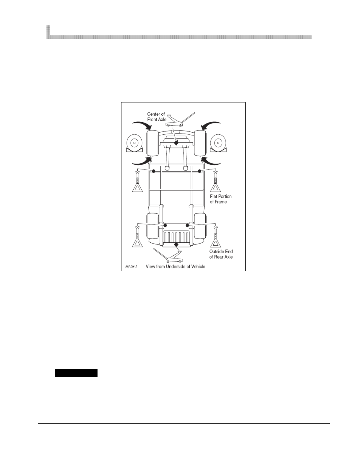
LIFTING THE VEHICLE
Tool List Qty. Required
Floor jack ………………… 1
Jack stands ……………… 4
Chocks ………………… 4
Some servicing operations may require the front wheels, the rear wheels, or the entire vehicle be raised.
! WARNING ! To reduce the possibility of severe injury or death from a vehicle falling from a jack:
Be sure the vehicle is on a firm and level surface.
Never get under a vehicle while it is supported by a jack.
Use jack stands and test the stability of the vehicle on the stands.
Always place chocks in front and behind the wheels not being raised.
Use extreme care since the vehicle is extremely unstable during the lifting process.
! CAUTION ! When lifting vehicle, position jacks and jack stands at the areas indicated only.
To raise the entire vehicle, install chocks in front and behind each front wheel. Center the jack under the rear
frame crossmember. Raise the vehicle enough to place a jack stand under the outer ends of the rear axle.
Lower the jack and test the stability of the vehicle on the two jack stands.
Place the jack at the center of the front axle. Raise the vehicle enough to place jack stands under the frame
crossmember as indicated.
Page 19
OPERATION AND SERVICE INFORMATION
16
Owner’s Manual and Service Guide
Lower the jack and test the stability of the vehicle on all four jack stands.
If only the front or rear of the vehicle is to be raised, place the chocks in front and behind each wheel not
being raised to stabilize the vehicle.
Lower the vehicle by reversing the lifting sequence.
Fig.6 Lifting the Vehicle
WHEELS AND TIRES
Tire Repair
Tool list Qty. Required
Lug wrench, 3/4”……… ……… 1
Impact socket, 3/4”, 1/2” drive …… 1
Impact wrench, 1/2” ……………… 1
Torque wrench, 1/2”drive………… 1
! WARNING ! A tire explosion can cause severe injury or death. Never exceed inflation pressure
rating on tire sidewall.
To reduce the possibility of tire explosion, pressurize tire with small amount of air applied
intermittently to seat beads. Due to the low volume of the small tires, overinflation can occur in seconds.
Never exceed the tire manufacturer’s recommendation when seating a bead. Protect face and eyes from
escaping air when removing valve core.
Page 20

OPERATION AND SERVICE INFORMATION
17
Owner’s Manual and Service Guide
To reduce the possibility of severe injury caused by a broken socket when removing wheels, use only
sockets designed for impact wrench use.
Use caution when inflating tires. Over inflation could cause the tire to separate from the wheel or cause
the tire to explode, either of which could cause severe injury.
Use caution when inflating tires. Due to the low volume of the small tires, overinflation can occur in seconds.
Over-inflation could cause the tire to separate from the wheel or cause the tire to explode.
Tire inflation should be determined by the condition of the terrain. For outdoor application with major use on
grassy areas, the following should be considered. On hard turf, it is desirable to have a slightly higher
inflation pressure. On very soft turf, a lower pressure reduces the possibility of tires cutting into the turf. For
vehicles being used on paved or hard surfaces, tire inflation pressure should be in the higher allowable range,
but under no condition should inflation pressure be hi gher than recommended on tire sidewall. All four tires
should have the same pressure for optimum handling characteristics. Be sure to install the valve dust cap after
checking or inflating.
NOTE Tire plug tools and plugs are available at most automotive parts outlets and have the advantage of
not requiring the tire be removed from the wheel.
If the tire is flat, remove the wheel and inflate the tire to the maximum recommended pressure for the tire.
Immerse the tire in water to locate the leak and mark with chalk. Insert tire plug in accordance with
manufacturer’s instructions.
! WARNING ! To reduce the possibility of severe injury, be sure mounting/demounting
Machine is anchored to floor. Wear OSHA approved safety equipment when mounting/demounting
tires.
If the tire is to be removed or mounted, the tire changing machine manufacturer’s recommendations must be
followed in order to reduce possibility of severe injury.
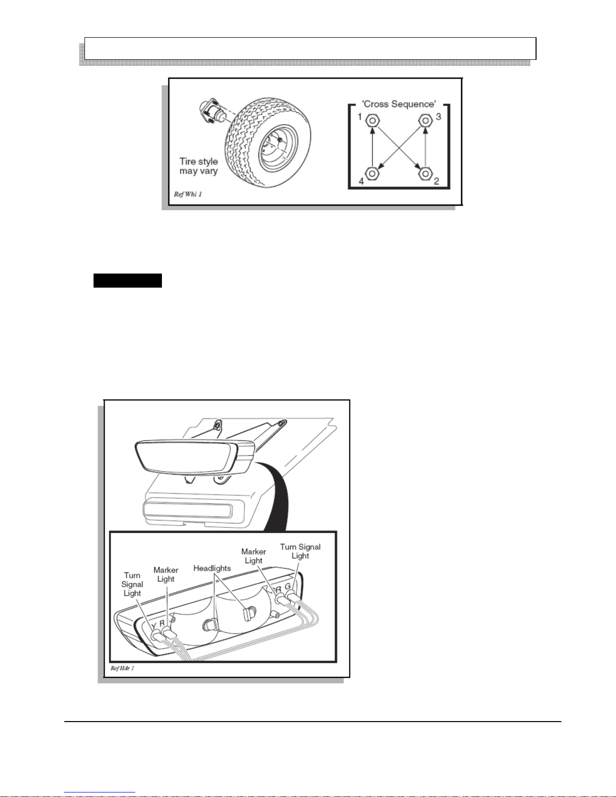
Wheel Installation
! CAUTION ! tTo reduce the possibility of component damage, do not tighten lug nuts to more than
85ft.lbs.(115 Nm) torque.
NOTE It is important to follow the ‘cross sequence’ pattern when installing lug nuts. This will assure even
seating of the wheel against the hub.
With the valve stem to the outside, mount the wheel onto the hub with lug nuts. Finger tighten lug nuts in a
‘cross sequence’ pattern (Ref Fig.7). Tighten lug nuts to 76-102Nm.
Page 21
OPERATION AND SERVICE INFORMATION
18
Owner’s Manual and Service Guide
Fig.7 Wheel Installation
LIGHT BULB REPLACEMENT
! CAUTION ! To reduce the possibility of premature bulb failure, do not touch new bulbs with bare
fingers. Use clean, dry tissue or paper towel to handle the glass portion of the bulb.
For vehicles equipped with lights mounted below cowl, locate bulb socket on backside of light bar (Ref Fig. 8)
and turn bulb socket a quarter turn counterclockwise to unlock and pull out bulb. Insert new bulb and rotate
socket a quarter turn clockwise to secure.
To replace the tail and brake light bulb, remove hardware securing lens and remove lens. (Ref Fig. 9).Install
replacement bulb.
Fig. 8 Headlight, Turn Signal & Marker Light Bulb Replacement
Page 22

OPERATION AND SERVICE INFORMATION
19
Owner’s Manual and Service Guide
Fig. 9 Tail and Brake Light Bulb Replacement
SERVICE AND MAINTENANCE
! WARNING ! To reduce the possibility of severe injury or death from improper servicing techniques:
Do not attempt any type of servicing operations before reading and understanding all notes, cautions and
warnings in this manual.
Any servicing requiring adjustments to be made to the powertrain while the motor is running must be made
with both drive wheels raised and vehicle properly supported on jack stands.
To reduce the possibility of motor damage, never operate vehicle at full throttle for more than 4-5 seconds
while vehicle is in a “no load” condition.
Wear eye protection when working on the vehicle. Use extra care when working around batteries, or using
solvents or compressed air.
To reduce the possibility of causing an electrical arc, which could result in a battery explosion, turn off all
electrical loads from the battery before removing battery wires.
Wrap wrenches with vinyl tape to reduce the possibility of a dropped wrench “shorting out” a battery, which
could result in an explosion.
Reduce the possibility of accidental starting by removing and grounding spark plug wires and disconnecting
battery at negative terminal before servicing.
The electrolyte in a battery is an acid solution which can cause severe burns to the skin and eyes. Treat all
electrolyte spills to the body and eyes with extended flushing with clear water. Contact a physician
immediately.
Page 23

OPERATION AND SERVICE INFORMATION
20
Owner’s Manual and Service Guide
Any electrolyte spills should be neutralized with a solution of 2 teaspoons (10ml) sodium bicarbonate
( braking soda) dissolved in 1 quart ( 1 liters ) of water and flushed with water.
It is in the best interest of both vehicle owner and service technician, to carefully follow the procedures
recommended in this manual. Preventative maintenance, applied at recommended intervals is the best
guarantee for keeping the vehicle both dependable and economical.
This vehicle will give years of satisfactory service, providing it receives regular maintenance. Refer to the
Periodic Service Schedule for appropriate service intervals.
! CAUTION ! To prolong vehicle life, some maintenance items must be serviced more frequently on
vehicles used under severe driving conditions such as extreme temperatures, extreme dust/debris
conditions, frequent use with maximum load.
PERIODIC SERVICE SCHEDULE
NOTE Some maintenance items must be serviced more frequently on vehicles used under severe driving
conditions
DAILY
BEFORE USE:
. Check service brake general operation
. Check park brake function
. Check warning device function in reverse
. Check tire condition
. Check overall vehicle condition
. Recharge batteries to full state of charge after each day’s use
. Inspect charger connector and receptacle at each charge
WEEKLY
TIRES . Examine for cuts, excessive wear and pressure (See GENERAL SPECIFICATIONS)
WHEELS . Check for bent rims, missing or loose lug nuts
MONTHLY - 20 HOURS
BATTERIES
. Clean batteries & terminals. See BATTERY CLEANING.
.Check charge condition and all connections
WIRING . Check all wiring for loose connections and broken insulation
CHARGER / RECEPTACLE . Clean connections, keep receptacles free of dirt and foreign matter
ACCELERATOR . Check for smooth movement
SERVICE BRAKE
(MECHANICAL BRAKES) . Conduct brake performance test
PARK BRAKE . Check brake performance and adjust if required
DIRECTION SELECTOR . Check attachment, tighten if required
Page 24

OPERATION AND SERVICE INFORMATION
21
Owner’s Manual and Service Guide
STEERING ASSEMBLY . Check for abnormal play, tightness of all hardware
TIE ROD/LINKAGES . Check for excessive play, bent components or loose connections
REAR AXLE . Check for leakage, add lubricant level as required
QUARTERLY - 50 HOURS
FRONT AXLE . Check for damage to axle and loose or missing hardware
FRONT SHOCK ABSORBERS . Check for oil leakage and loose fasteners
FRONT SPRINGS . Check for loose hardware, cracks at attachments
FRONT WHEEL ALIGNMENT .Check for unusual tire wear, align if required
PARK BRAKE
. Check for bent/binding linkage rod
. Check for damage or wear to latch arm or catch bracket
. Lubricate as required, use light oil. DO NOT LUBRICATE CABLES OR BRAKE LATCH
REAR SHOCK ABSORBERS . Check for oil leakage, loose mounting hardware
CHARGER PLUG . Clean auxiliary contact (see BATTERY CHARGER MAINTENANCE)
HARDW ARE AND FASTENERS
. Check for loose or missing hardware and components
. Tighten or replace missing hardware
SEMI-ANNUAL - 125 HOURS
DIRECTION SELECTOR . Check for wear and smooth movement (lubricate shaft with light oil if
required)
KING PINS . Check for excessive play and tightness of retaining nuts
STEERING ASSEMBLY . Check bellows and pinion seal for damage or grease leakage
RACK END BALL JOINT . Lubricate, use wheel bearing grease
REAR AXLE . Check for unusual noise and loose or missing mounting hardware
ANNUAL - 250-300 HOURS
FRONT WHEEL BEARINGS . Check and adjust as required, see Technician’s Repair and Service Manual
REAR AXLE . Check lubricant, add lubricant level as required
SERVICE BRAKES
. Clean and adjust
. Check brake shoe linings
TIRE INSPECTION
Tire condition should be inspected per the Periodic Service Schedule. Inflation pressures should be checked
when the tires are cool. Be sure to install the valve dust cap after checking or inflating.
BRAKES
! WARNING ! To reduce the possibility of severe injury or death, always evaluate pedal travel before
operating a vehicle to verify some braking function is present.
All driving brake tests must be done in a safe location with regard for the safety of all personnel.
Page 25

OPERATION AND SERVICE INFORMATION
22
Owner’s Manual and Service Guide
NOTE Over time, a subtle loss of performance may take place , therefore, it is important to establish the
standard with a new vehicle.
The Periodic Brake Performance Test should be performed regularly ( Ref. Fig. 16 ) as an evaluation of
braking system performance. It is useful as a method of identifying subtle loss of performance over time.
Periodic Brake Test for Mechanical Brake
The purpose of this test is to compare the braking performance of vehicle to the braking performance of new
or “known to be good” vehicle or to an established acceptable stopping distance. Actual stopping distances
will be influenced by weather conditions, terrain, rod surface condition, actual vehicle weight (accessories
installed) and vehicle speed. The test is conducted by latching the parking brake to eliminate different pedal
pressures and to include the affects of linkage misadjustment.
Establish the acceptable stopping distance by testing a new or “know to be good” vehicle and recording the
stopping location or stopping distance. For fleets of vehicles, several vehicles should be tested when new and
the range of stopping locations or distances recorded.
NOTE Over time, a subtle loss of performance may take place; therefore, it is important to establish the
standard with a new vehicle.
Drive the vehicle at maximum speed on a flat, dry, clean paved surface ( Ref. Fig 10).Quickly depress the
brake pedal to latch the parking brake at the line or
Page 26

OPERATION AND SERVICE INFORMATION
23
Owner’s Manual and Service Guide
Fig.10 Typical Brake Performance Test
marker in the test area and remove foot from pedal. The vehicle should stop aggressively. The wheel brakes
may or may not lock. Observe the vehicle stopping location or measure the vehicle stopping distance from
the point at which the brakes were latched. The vehicle should stop within the ‘normal’ range of stopping
distances. If the vehicle stops more than 4 ft. ( 3.0m) beyond the accept able stopping dist ance or pull s to one
side, the vehicle has failed the test and should be tested again.
If the vehicle fails the second test, it should immediately be removed from service. The vehicle must be
inspected by a qualified mechanic who should refer to the TROUBLESHOOTING section in the Technician’s
Repair and Service Manual.
REAR AXLE
The only maintenance required for the first three years is the periodic inspection of the lubricant level. The
rear axle is provided with a lubricant level check/fill plug located on the bottom of the differential (Ref Fig.
Page 27

OPERATION AND SERVICE INFORMATION
24
Owner’s Manual and Service Guide
11) (Ref Fig. 12). Unless leakage is evident, the lubricant need only be replaced after three years.
Fig.11 Add, Check and Drain Axle Lubricant-Early Production
Fig.12 Add, Check and Drain Axle Lubricant-Late Production
Checking the Lubricant Level
Clean the area around the check/fill plug and remove plug. The correct lubricant level is just below the
bottom of the threaded hole. If lubricant is low, add lubricant as required. Add lubricant slowly until lubricant
starts to seep from the hole. Install the check/fill plug. In the event that the lubricant is to be replaced, the
vehicle must be elevated and the oil pan removed or the oil siphoned through the check/fill hole.
LUBRICATION
CAUTION Do not use more than 1/2 ~ 3/4 of grease in any grease fitting at any one time. Excess
grease may cause grease seals to fail or grease migration into areas that could damage components.
Putting more than three pumps of grease in a grease fitting could damage grease seals and cause premature
bearing failure (Ref Fig.13 & Fig. 14)
Page 28

OPERATION AND SERVICE INFORMATION
25
Owner’s Manual and Service Guide
Fig.13 Lubrication Points-Early Production
Fig.14 Lubrication Points-Late Production
HARDWARE
Periodically, the vehicle should be inspected for loose fasteners. Fasteners should be tightened in accordance
with the Torque Specifications table (Ref Fig. 15).
Bolt
Grad
e
Bolt size D/MM
6 8 10 12 14 16 18 20
Torque (N·M)
4.8 4-5 10-12 20-25 35-44 54-69 99-108 118-147 167-206
Page 29

OPERATION AND SERVICE INFORMATION
26
Owner’s Manual and Service Guide
5.6 5-7 12-15 25-31 44-54 69-88 108-137 147-186 206-265
6.6 6-8 14-18 29-39 49-64 83-98 127-157 176-216 245-314
8.8 9-12 22-29 44-58 76-102 121-162 189-252 260-347 369-492
10.9
13-1
4
29-35 64-76 108-127 176-206 274-323 372-441 529-637
12.9
15-2
0
37-50 74-88 128-171 204-273 319-425 489-565 622-830
Figure 15
BA TTERIES AND CHARGING
SAFETY
NOTE Always observe the following warnings when working on or near batteries:
! WARNING ! To prevent battery explosion that could result in severe personal injury or
death, keep all smoking materials, open flame or sparks away from the batteries.
Hydrogen gas is formed when charging batteries. Do not charge batteries without adequate ventilation.
A 4% concentration of hydrogen gas is explosive.
Be sure that the key switch is off and all electrical accessories are turned off before starting work on
vehicle.
Never disconnect a circuit under load at a battery terminal.
Batteries are heavy. Use proper lifting techniques when moving them. Always lift the battery with a
commercially available battery lifting device. Use care not to tip batteries when removing or installing
them; spilled electrolyte can cause burns and damage.
The electrolyte in a storage battery is an acid solution which can cause severe burns to the skin and
eyes. Treat all electrolyte spills to the body
and eyes with extended flushing with clear water. Contact a physician immediately.
Always wear a safety shield or approved safety goggles when adding
water or charging batteries.
Any electrolyte spills should be neutralized with a solution of 1/4 cup (60 ml) sodium bicarbonate
(baking soda) dissolved in 1 1/2 gallons (6 liters)
of water and flushed with water.
Overfilling batteries may result in electrolyte being expelled from the battery during the charge cycle.
Page 30

OPERATION AND SERVICE INFORMATION
27
Owner’s Manual and Service Guide
Expelled electrolyte may cause damage to the vehicle and storage facility.
Aerosol containers of battery terminal protectant must be used with extreme care. Insulate metal
container to prevent can from contacting battery terminals which could result in an explosion.
Wrap wrenches with vinyl tape to prevent the possibility of a dropped wrench from ‘shorting out’ a
battery, which could result in an explosion and severe personal injury or death.
Ventilation for electric-powered golf cars shall be provided, to remove the accumulation of flammable
hydrogen gas emitted during the charging process. Because of the highly volatile nature of hydrogen
gas and its propensity to rise and accumulate at the ceiling in pockets, a minimum of 5 air changes per
hour is recommended for multiple vehicles and one air change per hour may be adequate for one
vehicle. The controlling party shall consult applicable fire and safety codes for the specific ventilation
levels required.
The controlling party shall require battery changing and charging facilities and procedures to be in
accordance with applicable ordinances or regulations. The controlling party shall periodically inspect
charging and storage areas or facilities and review procedures to be certain.
BATTERY
A battery is defined as two dissimilar metals immersed in an acid. If the acid is absent or if the metals are not
dissimilar, a battery has not been created. The batteries most commonly used in these vehicles are lead acid.
A battery does not store electricity, but is able to produce electricity as the result of a chemical reaction which
releases stored chemical energy in the form of electrical energy. The chemical reaction takes place faster in
warm conditions and slower in cold conditions. Temperature is important when conducting tests on a battery
and test results must be corrected to compensate for temperature
differences.
As a battery ages, it still performs adequately except that its capacity is diminished. Capacity describes the
time that a battery can continue to provide its design amperes from a full charge.
A battery has a maximum life, therefore good maintenance is designed to maximize the available life and
reduce the factors that can reduce the life of the battery.
BATTERY MAINTENANCE
Tool List Qty. Required
Insulated wrench, 9/16"............................................1
Battery carrier........................................................... 1
Hydrometer................................................................1
Battery maintenance kit P/N 25587-G01..................1
At Each Charging Cycle
Page 31

OPERATION AND SERVICE INFORMATION
28
Owner’s Manual and Service Guide
! WARNING ! To reduce the possibility of fire, never attach a battery charger to a vehicle that is to
be unattended beyond the normal charging cycle. Overcharging could cause damage to the vehicle
batteries and result in extreme overheating. The charger should be checked after 24 hours and
unplugged after the charge cycle is complete.
Before charging the batteries, inspect the plug of the battery charger and vehicle receptacle housing for dirt or
debris.
Charge the batteries after each days use.
Monthly
Inspect all wiring for fraying, loose terminations, corrosion or deterioration of insulation.
Check that the electrolyte level is correct and add suitable water as required.
Clean the batteries and wire terminations.
Electrolyte Level and Water
The correct level of the electrolyte is 1" (25 mm) above the plates in each cell (Ref Fig. 16).
Fig.16 Correct Electrolyte Level
This level will leave approximately 3/4" ( 19.5 mm) of space between the electrolyte and the vent tube. The
electrolyte level is important since any portion of the plates exposed to air will be ruined beyond repair. Of
equal importance is too much water which will result in electrolyte being forced out of the battery due to
gassing and the increase in volume of the electrolyte that results
from the charging cycle.
CAUTION Do not overfill batteries. The charging cycle will expel electrolyte and result in component
damage.
Page 32

OPERATION AND SERVICE INFORMATION
29
Owner’s Manual and Service Guide
A battery being charged will ‘gas’ with the majority of the gassing taking place at the end of the charging
cycle. This gas is hydrogen which is lighter than air. Water and sulfuric acid droplets will be carried out of the
battery vents by the hydrogen gas; however, this loss is minimal. If the battery electrolyte level is too high,
the electrolyte will block the vent tube and the gas will force it out of the vent tube and battery cap. The water
will evaporate but the sulfuric acid will remain where it can damage vehicle components and the storage
facility floor. Sulfuric acid loss will weaken the concentration of acid within the electrolyte and reduce the
life of the battery.
Over the life of the battery, a considerable amount of water is consumed. It is important that the water used be
pure and free of contaminants that could reduce the life of the battery by reducing the chemical reaction. The
water must be distilled or purified by an efficient filtration system. Water that is not distilled should be
analyzed and if required, filtration installed to permit the water to
meet the requirements of the water purity table (Ref Fig.17).
Fig.17 Water Purity Table
Even if the water is colorless, odorless, tasteless and fit for drinking, the water should be analyzed to see that
it does not exceed the impurity levels specified in the table.
Battery Cleaning
CAUTION To prevent battery damage, be sure that all battery caps (if equipped) are tightly installed.
To reduce the possibility of damage to vehicle or floor, neutralize acid before rinsing battery.
To reduce the possibility of damage to electrical components while cleaning, do not use a pressure
washer.
Cleaning should take place per the Periodic Service Schedule (Ref. Fig. 16).
Page 33

OPERATION AND SERVICE INFORMATION
30
Owner’s Manual and Service Guide
When cleaning the outside of batteries and terminals, first spray with a solution of sodium bicarbonate
(baking soda) and water to neutralize any acid deposits before
rinsing with clear water.
Use of a water hose without first neutralizing any acid will move acid from the top of batteries to another area
of the vehicle or storage facility where it will attack the metal
structure or the concrete/asphalt floor. Additionally, conductive residue will remain on the batteries and
contribute to their self discharge.
!WARNING ! To reduce the possibility of battery explosion that could result in severe injury or death,
do not use metallic spray wand to clean battery and keep all smoking materials, open flame or sparks
away from the battery
The correct cleaning technique is to spray the top and sides of the batteries with a solution of sodium
bicarbonate (baking soda) and water. This solution is best applied
with a garden type sprayer equipped with a non metallic spray wand or plastic spray bottle. The solution
should consist of the ingredients shown in the illustration (Ref Fig.18). In addition, special attention should
be paid to metal components adjacent to the batteries which should also be sprayed with the solution.
Fig.18 Preparing Acid Neutralizing Solution
Allow the solution to sit for at least three minutes. Use a soft bristle brush or cloth to wipe the tops of the
batteries to remove any conductive residue. Rinse the entire area
with low pressure clear water. Do not use a pressure washer. All of the items required for complete battery
cleaning and watering (electric vehicles only) are contained in the Battery Maintenance Kit.
Battery Replacement
Remove battery hold downs and cables. Lift out batteries with a commercially available lifting device.
Page 34

OPERATION AND SERVICE INFORMATION
31
Owner’s Manual and Service Guide
If the batteries have been cleaned and any acid in the battery rack area neutralized as recommended, no
corrosion to the battery racks or surrounding area should be present. Any corrosion found should be
immediately removed with a putty knife and a wire brush. The area should be washed with a solution of
sodium bicarbonate (baking soda) and water and thoroughly dried before priming and painting with a
corrosion resistant paint.
The batteries should be placed into the battery racks and the battery hold downs tightened to 45 - 55 in. lbs.
(5 - 6 Nm) torque, to prevent movement but not tight enough to cause distortion of the battery cases.
Inspect all wires and terminals. Clean any corrosion from the battery terminals or the wire terminals with a
solution of sodium bicarbonate (baking soda) and brush clean if
required.
!WARNING! To prevent battery explosion that could result in severe personal injury or death,
extreme care must be used with aerosol containers of battery terminal protectant. Insulate the metal
container to prevent the metal can from contacting battery terminals which could result in an
explosion.
Use care to connect the battery wires as shown (Ref Fig. 19). Tighten the battery post hardware to 50 70 in.
lbs. (6 -8 Nm) torque. Protect the battery terminals and battery wire terminals with a commercially available
protective coating.
Fig.19 Battery Connections
Prolonged Storage
CAUTION Battery charger, controller and other electronic devices need to be disconnected since they
will contribute to the premature discharge of batteries.
During periods of storage, the batteries will need attention to keep them maintained and prevent discharge.
In high temperatures the chemical reaction is faster, while low temperatures cause the chemical reaction to
slow down. A vehicle that is stored at 90° F (32° C) will lose .002 of specific gravity each day. If a fully
Page 35

OPERATION AND SERVICE INFORMATION
32
Owner’s Manual and Service Guide
charged battery has a specific gravity of 1.275, and the battery is allowed to sit unused, it will become
partially discharged. When it reaches 1.240, which it will do in less than twenty days, it should be recharged.
If a battery is left in a discharged state, sulfating takes place on and within the plates. This condition is not
reversible and will cause permanent damage to the battery. In order to prevent damage, the battery should be
recharged. A hydrometer can be used to determine the specific gravity and therefore the state of charge of a
battery.
In winter conditions, the battery must be fully charged to prevent the possibility of freezing (Ref Fig. 29 on
page 23). A fully charged battery will not freeze in temperatures above -75° F (-60° C). Although the
chemical reaction is slowed in cold temperatures, the battery must be stored fully charged, and disconnected
from any circuit that could discharge the battery. For portable chargers, disconnect the charging plug from the
vehicle receptacle. The batteries must be cleaned and all deposits neutralized and removed from the battery
case to prevent self discharge. The batteries should be tested or recharged at thirty day minimum intervals.
BATTERY CHARGING
The battery charger is designed to fully charge the battery set. If the batteries are severely deep cycled, some
automatic battery chargers contain an electronic module
that may not activate and the battery charger will not function. Automatic chargers will determine the correct
duration of charge to the battery set and will shut off when the battery set is fully charged. Always refer to the
instructions of the specific charger used.
Before charging, the following should be observed:
CAUTION Do not overfill batteries. The charging cycle will expel electrolyte and result in component
damage.
z The electrolyte level in all cells must be at the recommended level and cover the plates.
Page 36

OPERATION AND SERVICE INFORMATION
33
Owner’s Manual and Service Guide
Fig.20 Freezing Point of Electrolyte
z The charging must take place in an area that is well ventilated and capable of removing the hydrogen gas
that is generated by the charging process. A minimum of five air exchanges per hour is recommended.
z The charging connector components are in good condition and free from dirt or debris.
z The charger connector is fully inserted into the vehicle receptacle.
z The charger connector/cord set is protected from damage and is located in an area to prevent injury that
may result from personnel running over or tripping over the cord set.
z The charger is automatically turned off during the connect/disconnect cycle and therefore no electrical
arc is generated at the DC plug/receptacle contacts.
NOTE In our chargers, there is a jiggle switch inside charger receptacle. The switch is part of the interlock
system that prevents the vehicle from being driven when the charger plug is inserted in the vehicle charging
receptacle. (Fig 21)
Fig. 21 Jiggle Switch inside of charger receptacle
Page 37

OPERATION AND SERVICE INFORMATION
34
Owner’s Manual and Service Guide
TROUBLESHOOTING
In general, troubleshooting will be done for two distinct reasons. First, a battery that performs poorly and is
outside of the manufacturers specification should be identified in order to replace it under the terms of the
manufacturer’s warranty. Different manufacturers have different requirements. Consult the battery
manufacturer or a manufacturer representative for specific requirements.
The second reason is to determine why a particular vehicle does not perform adequately. Performance
problems may result in a vehicle that runs slowly or in a vehicle that is unable to operate for the time
required.
A new battery must mature before it will develop its maximum capacity. Maturing may take up to 100
charge/discharge cycles. After the maturing phase, the older a battery gets, the lower the capacity. The only
way to determine the capacity of a battery is to perform a load test using a discharge machine following
manufacturer’s recommendations.
A cost effective way to identify a poorly performing battery is to use a hydrometer to identify a battery in a
set with a lower than normal specific gravity. Once the particular cell or cells that are the problem are
identified, the suspect battery can be removed and replaced. At this point there is nothing that can be done to
salvage the battery; however, the individual battery should be replaced with a good battery of the same brand,
type and approximate age.
Hydrometer
A hydrometer (P/N 50900-G1) is used to test the state of charge of a battery cell (Ref Fig. 22). This is
performed by measuring the density of the electrolyte, which is accomplished by measuring the specific
gravity of the electrolyte. The greater the concentration of sulfuric acid, the more dense the electrolyte
becomes. The higher the density, the higher the state of charge.
!WARNING ! To prevent battery explosion that could result in severe personal injury or death, never
insert a metal thermometer into a battery. Use a hydrometer with a built in thermometer
Page 38

OPERATION AND SERVICE INFORMATION
35
Owner’s Manual and Service Guide
Fig.22 Hydrometer
Specific gravity is the measurement of a liquid that is compared to a baseline. The baseline is water which is
assigned a base number of 1.000. The concentration of sulfuric acid to water in a new golf car battery is 1.280
which means that the electrolyte weighs 1.280 times the weight of the same volume of water. A fully charged
battery will test at 1.275 -1.280 while a discharged battery will read in the 1.140 range.
NOTE Do not perform a hydrometer test on a battery that has just been watered.The battery must go
through at least one charge and discharge cycle in order to permit the water to adequately mix with the
electrolyte.
The temperature of the electrolyte is important since the hydrometer reading must be corrected to 80° F (27°
C). High quality hydrometers are equipped with an internal thermometer that will measure the temperature of
the electrolyte and will include a conversion scale to correct the float reading. It is important to recognize that
the electrolyte temperature is significantly different from the ambient temperature if the vehicle has been
operated.
Using A Hydrometer
1. Draw electrolyte into the hydrometer several times to permit the thermometer to adjust to the electrolyte
temperature and note the reading. Examine the color of the electrolyte. A brown or gray coloration indicates a
problem with the battery and is a sign that the battery is nearing the end of its life.
2. Draw the minimum quantity of electrolyte into the hydrometer to permit the float to float freely without
Page 39

OPERATION AND SERVICE INFORMATION
36
Owner’s Manual and Service Guide
contacting the top or bottom of the cylinder.
3. Hold the hydrometer in a vertical position at eye level and note the reading where the electrolyte meets the
scale on the float.
4. ρ25℃ = ρt +0.0007(t-25)
ρ25℃ ——25℃ electrolyte specific gravity ;
ρt ——t℃ electrolyte specific gravity;
5. Test each cell and note the readings (corrected to 80° Fig. 30 Hydrometer F or 27° C). A variation of fifty
points between any two cell readings (example 1.250 -1.200) indicates a problem with the low reading
cell(s).
As a battery ages the specific gravity of the electrolyte will decrease at full charge. This is not a reason to
replace the battery, providing all cells are within fifty points of each other.
Since the hydrometer test is in response to a vehicle exhibiting a performance problem, the vehicle should be
recharged and the test repeated. If the results indicate a weak cell, the battery or batteries should be removed
and replaced with a good battery of the same brand, type and approximate age.
BATTERY MAINTENANCE
Our experience shows that the key to achieving optimum performance and long life is a solid battery
maintenance program using the simple procedures
outlined here.
Equipment:
We recommends the following equipment for use in battery care and maintenance:
Recommended Equipment:
◆ Wrench
◆ Distilled Water
◆ Voltmeter
◆ Hydrometer
◆ Thermometer
◆ Post Cleaner
◆ Baking Soda
◆ Vaseline
◆ Goggles & Gloves
!CAUTION !: Always wear protective clothing, gloves, and goggles
when handling batteries, electrolyte, and charging your battery.
Page 40

OPERATION AND SERVICE INFORMATION
37
Owner’s Manual and Service Guide
Inspection
Batteries should be carefully inspected on a regular basis in order to detect and correct potential problems
before they can do harm. It is a great idea to start this routine when the batteries are first received.
Inspection Guildlines:
1. Examine the outside appearance of the battery.
◆ Look for cracks in the container.
◆ The top of the battery, posts, and connections should be clean, free of dirt, fluids, and corrosion.
◆ Repair or replace any damaged batteries.
2. Any fluids on or around the battery may be an indication that electrolyte spilling, leaching, or leaking out.
◆ Leaking batteries must be repaired or replaced.
3. Check all battery cables and their connections.
◆ Look closely for loose or damaged parts.
◆ Battery cables should be intact; broken or frayed cables can be extremely hazardous.
◆ Replace any cable that looks suspicious.
4. Tighten all wiring connections to the proper specification. Make certain there is good contact with the
terminals.
!WARNING !
◆ Do not smoke near batteries.
◆ Do not overtighten terminals. Doing so can result post breakage, post meltdown, or fire.
Specific Gravity Testing
1. Do not add water at this time.
2. Washing hydrometer with deionized water firstly。,
3. Fill and drain the hydrometer 2 to 4 times before pulling out a sample.
4. There should be enough sample electrolyte in the hydrometer to completely support the float.
5. Take a reading, record it, and return the electrolyte back to the cell.
6. Check electrolyte specific gravity for each cell, testing one cell g temperature by thermometer(often from
mid-cell) ;
7. Check all cells in the battery, repeating the steps above.
8. Replace the vent caps and wipe off any electrolyte that might have been spilled.
9.ρ25℃ = ρt +0.0007(t-25)
ρ25℃ ——25℃ electrolyte specific gravity ;
ρt ——t℃ electrolyte specific gravity.
10. Check the state of charge using Table on the next page.
The readings should be at or above the specification of 1.280±0.01g/cm3.
If any specific gravity readings register low, then follow the steps below:
1. Check and record voltage level(s).
2. Put battery(s) on a complete charge.
3. Take specific gravity readings again.
Page 41

OPERATION AND SERVICE INFORMATION
38
Owner’s Manual and Service Guide
If any specific gravity readings still register low then follow the steps below.
1. Check voltage level(s).
2. Perform charging. Refer to the charging section for the proper procedure.
3. Take specific gravity readings again.
If any specific gravity reading still registers lower than the specification of 1.280±0.01g/cm3 then one or
more of the following conditions may exist:
1. The battery is old and approaching the end of its life.
2. The battery was left in a state of discharge too long.
3. Electrolyte was lost due to spillage or overflow.
4. A weak or bad cell is developing.
5. Battery was watered excessively previous to testing.
Batteries in conditions 1 - 5 should be taken to a specialist for further evaluationor retired from service.
NOTE
◆ Do not smoke near batteries.
◆ Do not overtighten terminals. Doing so can result in post breakage, post meltdown, or fire.
NOTE electrolyte specific gravity is 1.10g/cm3 under full charging, if can not test or not air bubble in
cell during of charging, then short circuit happened.
Open-Circuit Voltage Test
For accurate voltage readings, batteries must remain idle (no charging, no discharging) for at least 6 hrs,
preferably 24 hrs.
1. Disconnect all loads from the batteries.
2. Measure the voltage using a DC voltmeter.
3. Check the state of charge with Table 1.
4. Charge the battery if it registers 0% to 70% charged.
If battery registers below the Table 1 values, the following conditions may exist:
1. The battery was left in a state of discharge too long.
2. The battery has a bad cell.
Batteries in these conditions should be taken to a specialist for further evaluation or retired from service.
TABLE 1. State of charge as related to specific gravity and open circuit voltage
Page 42

OPERATION AND SERVICE INFORMATION
39
Owner’s Manual and Service Guide
Percentage
of Charge(%)
Spec ific Gravity(g/cm)
Corrected to 25
3
℃
6V
8V 12V
100 1.28 6.37 8.49 1 2.73
90 1.26 6.31 8.41 12.62
80 1.24 6.25 8.33 12.50
70 1.22 6.19 8.25 12.37
60 1.20 6.12 8.16 12.24
50 1.18 6.05 8.07 12.10
40 1.15 5.98 7.97 11.96
30 1.13 5.91 7.88 11.81
20 1.10 5.83 7.77 11.66
10 1.07 5.75 7.67 11.51
open ci rcuit v oltage
Watering
(Flooded batteries only)
Flooded batteries need water. More importantly, watering must be done at the right time and in the right
amount or else the battery's performance and longevity suffers.
Water should always be added after fully charging the battery. Prior to charging, there should be enough
water to cover the plates. If the battery has been discharged (partially or fully), the water level should also be
above the plates.
Keeping the water at the correct level after a full charge will prevent having to worry about the water level at
a different state of charge.
1. Do not let the plates get exposed to air.
2. Do not fill the water all the way up to the cap.
3. Do not use water with a high mineral content.
4.Use distilled or deionized water only.
!CAUTION ! The electrolyte is a solution of acid and water so skin contact should be avoided.
Procedure:
1. Open the vent caps and look inside the fill wells. Check electrolyte level; the minimum level is at the top
Page 43

OPERATION AND SERVICE INFORMATION
40
Owner’s Manual and Service Guide
of the plates.
2. If there is no electrolyte visible, add just enough distilled/deionized water to cover the plates.
3.Replace and tighten all water vent caps.
4. Put batteries on a complete charge before adding any additional water (refer to the Charging section).
5. Once charging is completed, remove the vent caps and check the electrolyte level.
6. Add water until the electrolyte level is 1/8" below the bottom of the fill well.
7. Clean, replace, and tighten all vent caps.
!WARNING ! Never add acid to a battery.
CHARGING
Charging batteries properly requires administering the right amount of current at the right voltage. Most
charging equipment automatically regulates these values. Some chargers allow the user to set these values.
For proper charging, refer to the instructions that came with your charging equipment.
Important things to remember:
1. Become familiar with and follow the instructions issued by the charger manufacturer.
2. Batteries should be charged after each period of use.
3. Lead acid batteries do not develop a memory and need not be fully discharged before recharging.
4. Charge only in well-ventilated area. Keep sparks or flames away from a charging battery.
5. Verify charger voltage settings are correct .
6. Check electrolyte level.(See Watering section).
7. Tighten all ven t caps befo re charging.
8. Do not overcharging or undercharging the batteries.
9. Do not charge a frozen battery.
10. Avoid charging at temperatures above 48℃.
How To Increase System Power
Two or more batteries can be easily connected to boost your system’s voltage and/or capacity. There are three
methods to obtain additional voltage and/or capacity, as described below:
To increase voltage, connect batteries in series.
+
-
+
-
Battery System:12 Volt,226 AH Using Two DT106 Deep
Cycle Batteries(6 Volts,226AH)
To increase amp-hour capacity, connect batteries in parallel.
Page 44

OPERATION AND SERVICE INFORMATION
41
Owner’s Manual and Service Guide
+
-
+
-
Battery System:6 Volt,452 AH Using Two DT106 Deep Cycle Batteries(6 Volts,226AH)
To increase both voltage and amp-hour capacity, connect batteries in series/parallel.
+
-
+
-
+
-
+
-
Battery System: 12 Volt, 452 AH Using Four DT106 Deep Cycle Batteries(6 Volts,226 AH)
NOTE These systems can also be configured using 12-volt batteries. It is not recommended that you
mix batteries of different voltages within the same system.
CLEANING
Batteries seem to attract dust, dirt, and grime. Keeping them clean will help one spot trouble signs if they
appear and avoid problems associated with grime.
1. Check that all vent caps are tightly in place.
2. Clean the battery top with a cloth or brush and a solution of baking soda and water.
◆ When cleaning, do not allow any cleaning solution, or other foreign matter to get inside the battery.
3. Rinse with water and dry with a clean cloth.
4. Clean battery terminals and the inside of cable clamps using a post and clamp cleaner.
◆ Clean terminals will have a bright metallic shine.
5. Reconnect the clamps to the terminals and thinly coat them with petroleum jelly (Vaseline) to prevent
corrosion.
6. Keep the area around batteries clean and dry.
STORAGE
Periods of inactivity can be extremely harmful to lead acid batteries. When placing a battery into storage,
follow the recommendations below to insure that the battery remains healthy and ready for use.
Page 45

OPERATION AND SERVICE INFORMATION
42
Owner’s Manual and Service Guide
The most important things to avoid:
1. Freezing: Avoid locations where freezing temperature is expected. Keeping a battery at a high state of
charge will also prevent freezing. (See Table2)
2. Heat: Avoid direct exposure to heat sources, such as radiators or space heaters. Temperatures above 80°F
accelerate the battery's self-discharge characteristics.
Procedure:
1. Completely charge the battery before storing.
2. Store the battery in a cool, dry location, protected from the elements.
3. During storage, monitor the specific gravity (flooded) or voltage. Batteries in storage should be given a
boost charge when they show a 70% charge or less. See Table 1 in the Testing Section.
4. Completely charge the battery before re-activating.
5. For optimum performance, equalize the batteries (flooded) before putting them back into service. Refer to
the Equalizing section for this procedure.
Table2 Electrolyte Freezing Point @ Various States of Charge
Specific gravity
g/cm()
3
S t at e of ch ar ge(%)
Freezing
temperature( )℃
1.280
1.265
1.250
1.200
1.150
1.100
100%
92%
85%
62%
40%
20%
-68.9
-57.4
-52.2
-26.7
-15
-7.2
Battery Terms Explained
1. Active Material——In the positive plates, the active material is lead dioxide. In the negative, it’s metallic
sponge lead. When a circuit is created, these materials react with sulfuric acid during charging and
discharging.
2. Ampere (Amp)——A unit of measurement for the electron flow or current through a circuit.
3. Ampere-Hour (Amp. Hr., AH)——A unit of measure for a battery’s electrical storage capacity, calculated
by multiplying the current in amperes by the time in hours. ( Example: A battery which delivers 5 amps for
20 hours provides 5 amps ×20 hours = 100 AH of capacity.)
4. Capacity Rating——The time in minutes that a new, fully-charged battery will deliver 25 amperes or 75
amperes at 800F and maintain a terminal voltage equal to or greater than 1.75 volts per cell.
5. Cell——The basic current-producing unit in a battery. It consists of a set of positive plates, negative plates,
electrolyte, separators and casing, A cell’s nominal voltage is 2 volts.(Example: A 12-volt battery has 6 cells.)
6. Circuit——The path followed by a flow of electrons. A closed, or short, circuit is a complete path. An
Page 46

OPERATION AND SERVICE INFORMATION
43
Owner’s Manual and Service Guide
open circuit has a broken path.
7. Cycle——One discharge of a battery plus one recharge.
8. Depth of Discharge (DOD)——The percentage of capacity actually removed from a battery compared to
the total rated capacity.
9. Electrolyte——In a deep cycle battery, it is a dilute solution of sulfuric acid and water.
10. Hydrometer——A tool used to measure the specific gravity of the electrolyte solution.
11. Equalization——An overcharge performed on flooded lead-acid batteries after they have been fully
charged. This maintenance step helps eliminate stratification and sulfation.
12. Ohm (?——A unit of measurement for electrical resistance within a circuit.
13. Open Circuit Voltage——The voltage of a battery when there is no load attached(not receiving or
delivering energy).This measurement is best taken when the battery has been at rest for at least 6 hours.
14. Power Inverter——An electronic device that converts direct current (DC) power from a battery into
standard alternating current(AC)house power.
15. Primary Battery——An energy storage device that can deliver energy but cannot be recharged (i.e.,
disposable flashlight battery)
16. Secondary Battery——An energy storage device than can deliver energy and can be recharged.(i.e.,
automotive or deep cycle battery)
17. Separator——A divider made of porous material that is placed between the positive and negative plates
in a battery cell and allows current to flow through it, while preventing direct contact between the plates
which would cause a short circuit.
18. Specific Gravity(S.G.)——A measurement of the strength of battery electrolyte by comparing its
density to that of pure water.
19. Stratification——A condition where the concentration of acid is greater at the bottom of the battery that
at the top.
20. Sulfation ——The formation of lead sulfate on the positive and negative electrodes.
21. Volt (V)——A unit of measurement for electrical potential within a circuit.
22. Watt (W)——A unit of measurement for electrical power.
23. Watt Hout (Wh)——A unit of measurement for electrical power for a certain period of time.
Page 47

MAINTENANCE INFORMATION
Owner’s Manual and Service Guide
44
MAINTENANCE INFORMATION
Troubleshooting
No Problem Possible reason Processing methods
1 Under steering
1. Tire air pressure is over lower
2. Lubrication of turning part is not
good.
1. According to the requirement, to inflate the
tire.
2. Daub lubrication
2
Abnormal
abrasion for
tire
1. The toe-in is not correct
2. Tire air pressure is not correct
3. Overexert when braking
1. Adjust the toe-in
2. The air pressure of the four tires should be
coincident.
3. Adjust the stroke of brake pedal
3
Running speed
is slow
1. Battery voltage is over-low or
battery is aging
2. The running speed is low when
depressing the accelerate pedal
3. Connection joint of master circuit is
loose.
4. Arrester has fault that result in the cart
running with load.
1. Check the voltage of single battery, if it is
above 1V that indicates the battery is aging,
please replace it. It is advised to check the
electrolyte level which should be above the
plate 15-20mm, or please replace the battery.
2 .The accelerator pedal is loose, please fasten
the screws on the pedal; Measure the output
voltage of accelerating and the normal range is
0-5V, if it is beyond the range seriously, please
replace the accelerator.
3. Check each connection joint for loose, if
there is some problem, please pull the inserted
part out and adjust the inserted-spring of rubber
rind, then insert the terminal again.
4. Adjust the arrester.
4
Braking is not
in a good
condition
1. Brake compensator is loose
2. Brake shoe is attrited
1.Adjust brake draw-bar
2.Replace the brake shoe or brake cable
5
Cart can not
move
1.Without control power
2. Operation panel is disabled.
3.Over-low voltage and controller
protection
4. Running with over-load for a long
period that result in the controller overheat protection.
1. Check the control fuse respectively, if it is
broken please replace a new one; Check
jiggle switch on the charge socket for loose,
if so,please fasten it and the connection
cables; Turn on the keylock switch and the
input and output cables can not be
connected, please replace a new keylock
switch; The battery without a normal
working voltage, please charge it asap.
2. Check the connection cables on the
operation panel for loose, if so please fasten
it. When using the direction selector, the
control contact joint should be connected
and disconnected, or please replace it.
3. Charge battery asap.
4. After the temperature of controller bringing
down, the protection status recover immediately.
Page 48

MAINTENANCE INFORMATION
Owner’s Manual and Service Guide
45
Front / Rear bridge
Maintain the front suspension and steering system regularly.
1) Check all the spare parts for loose, abrasion and damage.
2) Lubricate the ball head joint and wheel bearing.
3) Check the caddie pedal, armrest and the bolts whether they are in a good condition.
Tool Qty
Butter gun 1 Pcs
Cover cap According to
the demand
1) Daub butter for the connection bal l he a d of the rack(1)
and drag bar (2,3) regularly . Clean the redundant butter
exuded from the cover after finished daubing.(Fig 1)
2) Check the bearing of the wheel a nd t h e cover of the lock
pin.
3) Jack up the front part of the cart, then rotate the front
wheel to check whether it is flat.
4) The tiny clearance between the claw axle and U plate is
a normal phenomena. If the clearance is too big, the
bearing should be added butter, adjusted or changed.
Please refer to section“The content of adjusting the rim
bearing for your reference.”
5) If the wheel hub bearing is in good condition, the claw axle should be replaced.
Please refer to section “replacing the claw axle.”
Lubricate the wheel hub bearing
Tool Qty
Butter gun 1pcs
1) Remove the wheel hub from the claw axle. Please refer to
section “Replace the hub bearing and dust cover”.
2) Clean the bearing, oil seal, wheel hub and the dust cover then
check them for damage. If there is spot or blue moulage on the
bearing, please replace a new one. Please refer to section
“Replace the hub bearing and dust cover”
3) The front wheel bearing is a t a pered roller bearing, you
should fill butter into it after each inspection.
4) Install the wheel hub and claw axle. Please refer to section
“Replace the wheel hub”.
Adjust the front wheel bearing
Tool Qty
½” Sleeve 1pcs
Torque wrench 1pcs
1/2”couplier 1pcs
1) Jack up the front part of the cart. Then rem ove t he dus t c o ve r (1) a n d c otte r pin (2 ) a n d lo ose n the
nut(3). (Fig 2)
2) If the wheel bearing inspection is only a part of the inspection plea se le ave the
Fig1
Fig2
Page 49

MAINTENANCE INFORMATION
Owner’s Manual and Service Guide
46
fixed spare parts of wheel on the cart.
3) Rotating the tire whilst fasteni ng the nut of the tire till there is resistance.
4) Rotate the tire for 2-3 circles to let the butter spread in the bearing equally. According to the
factual situation to fasten the nut till the cotter pin(2) can be installed. If not, please loosen the nut
little until you can insert the cotter pin into wheel.
5) Rotate the wheel to check radial cleara nc e and lock the cotter pin up.
6) Install the dust cover well and put down the cart.
Correct the toe-in
Tool Qty
Tapeline 1
9/16”Spanner 1
3/4” Spanner 1
3/4” Sleeve 1
Torque wrench 1
13mm Jacket 1
1) Jack up the front part of the cart and confirm the position of
spring armor plate. Please refer to section “Position correction of
front spring plate”.
2) Rotate both the wheels and remark in the middle of the wheel with chalk. Then
rotate it several circles to let the wheel in the normal running position.
3) Measure the length between the front wheels top point and
the rear wheels
top point, the front length should be shorter 2-6mm than rear
length.
4) Loosen the nut (1, 2) on the middle drag bar and the middle
rotated drag bar of the wheel to correct the toe-in in the
standard range. Torque for faste nin g the n ut is 36~4020IN.IBS
(49~54N.M). (Fig 3)
5) Confirm the steering wheel is in the middle position, then
disconnect the steering axle and steering wheel to correct the
position then fasten the screw, torque is 15.5~21.5N.M. (Fig 4)
Front suspension
Replace the front shock absorber
Tool Qty
9/16”Spanner 1 pcs
1) Remove the nut(1) at the b ot t om of the shock absorber(2) on the front axle(3).(Fig5)
2) Compress the shock absorber to let it depart from the bracket.
3) Loosen the connection nut between shock absorber and the frame, then rotate the shock absorber
with spanner.
4) Remove the shock absorber.
5) The step of installing the shock absorber is opposite to the step of removing it. Fasten the lower
lock nut till the rubber cushion is parallel with the shock absorber cushion.
6)
Replace the front beam
Fig3
Fig4
Page 50

MAINTENANCE INFORMATION
Owner’s Manual and Service Guide
47
Tool Qty
Speedness spanner,1/2”couplier 1 pcs
3/4”jacket,1/2”couplier 1 pcs
9/16”Spanner 1 pcs
3/4” Spanner 1 pcs
Plastic hammerhead 1 pcs
5/8”Spanner 1 pcs
11/16”Spanner 1 pcs
9/16” jacket,1/2”couplier 1 pcs
5/8” jacket,1/2”couplier 1 pcs
Torque wrench,1/2”couplier 1 pcs
1) Loosen the front wheel, then jack up the cart.
2) Remove the spare parts(1,4,5) which connect
with the shock absorber(2)
3) Remove the locknut(6) ,washer(8,9), screw(7),
thrust washer(11),core pin(12) an d ke ep them
well.
4) Remove the spare parts of the other side as
above method.
5) Remove the spare parts from the connection
rack assembly(16) and keep them well, then
fix the rack assembly on the armor plate spring.
6) Remove the three
1 3/4 screws(18), two 1 ½ screws(28), spring piece(24), and
five locknuts on the front beam, and the locknuts can be used again.
7) Remove other connection spare parts separately and keep them well for assembling again.
8) The steps for assembling the beam is opposite to remove it and the connection spare parts(18-
24,28)should be assembled at the former position.
9) The torque of (13~15,18~21,28)is 35-50N.M.
10) Assemble the thrust pad(11), core p i n ( 12 ), claw, washer(9) and screw(7) and the torque for
fastening the locknut is 56-60N.M.
11) Fasten the connector of the shock absorber, and the
locknut on the nether-end should be fastened to let the
rubber cushion and
shock absorber keep parallel.
12) After assembling the wheels put the cart down safely.
13) Check the front wheels for correct position, if
necessary please correct the toe-in. Details are given
in “correct the front wheel part”.
Replace the front spring armor plate
Tool Qty
Jack 1pcs
1) After releasing the screws of the wheels jack up the cart safely and the jack
should support at the front beam, then take the front wheels away.
2) Replace the beam. Remove the nuts(15)of the rack assembly and the locknuts
can not be used again.
Fig5
Fig6
Page 51

MAINTENANCE INFORMATION
Owner’s Manual and Service Guide
48
3) Remove both the 1 ¾ screws(18) and locknuts(19) and the locknuts can not be used again.
4) Remove the nut(21),long screw(20) and the armor plate(24). The spare parts 20-24 should be
kept well to install the former position.
5) Undraw the skidproof foot cushion to ta ke out the spare parts for fixing the armor plate(25-27).
6) The steps for assembling the spring armor plate is opposite to remove it and the removed long
screws(20), armor plate(24), washer(23,25),nut(21) should be assembled at the former position.
7) Replace the beam.
8) Remove the connection spare pa rts(18,19,24,28) between the axle(3) and armor pla te sp ring(17)
and the locknuts can be used again.
9) Undraw the skidproof cushion an d take o ut the spare parts for fixing the spring armor plate(25-
27) and the locknuts(19) can not be used again.
10) Use the new locknut(19,27) according to the steps that
opposite to the
remove steps to assemble the spring armor plate.
11) After assembling the spring armor plate please correct
the frame’s position and
the diagonal distances of mid-top screws on both the
spring armor plate
should be equal. Firstly, fasten the nut( 2 1,19,27), then
fasten the fixing nut of the rack an d the t o rque is
35~50N.M.(Fig6)
12) Assemble the skidproof cushion.
13) Check the toe-in of the front wheels and adjust it
according to demand. Details are given in “correct the
toe-in of the front wheel part”.
Replace the wheel hub (Fig 7)
Tool Qty
¾” jacket 1pcs
Parallel screwdriver 1pcs
½”jacket 1pcs
Butter used for the axle 1pcs
1) After releasing the screws o f the wheels jack up the
cart safely, then take the front wheels away.
2) Remove the dustproof cover(1), cotter pin(2) and the
screw cap of the wheel hub. Take out the bea r ing(4),
then remove the wheel hub(5 ) from claw(6)and the
hub can not be used again.
3) Clean the claw and new wheel hub completely and
butter the new bearing.
Details are given in the “Lubricate the wheel bearing”
part.
4) Daub some lightweight lubrication to the inner
surface of the bearing(7). As the right side picture,
install the oil seal well and lubricate it with butter gun.(Fig8)
5) Install the new wheel hub and fill 1/2~3/4 butter to both the bearing.
Fig8
Fig7
Fig9
Page 52

MAINTENANCE INFORMATION
Owner’s Manual and Service Guide
49
6) Install the outer bearing(4) and fasten the wheel hub to the proper position with nut. Then install
the wheel and fasten the screws by hand.
7) Adjust the bearing. Details are give in the “Adjust the wheel bearing” part.
8) Install the dustproof cover(1).
9) Put the cart down safely and fasten the wheel. Details are give in the “Tyre” part.
Replace the wheel bearing assembly (Fig9)
1) Remove the wheel hub(1) from the claw. Details are given in the “Replace the wheel hub”part.
2) Take out oil seal(3), inner wheel bearing(4), outer axle ring(5). When removing please
attention not to knock the inner hole of the wheel hub. Then clean the outer bearing(6), inner
bearing(4), wheel hub and dus tproof cover(7) and if the bearing is broken please replace a ne w
one.
3) When installing the bearing outer ring(5), make
sure the inner hole of the wheel hub is clean. The
operation step of the other side is as the same.
4) Clean the claw(2) and lubricate it.
5) Install the inner bearing (4), and after lubricating
the wheel hub install it
6) Adjust the wheel bearing. Details are given in the
“Replace the wheel bearing” part.
7) Install the dustproof cover(7).
8) Put down the cart carefully.
Replace the rack ball joint
1) Release the front wheel and jack up the cart
safely.
2) Remove the front wheel and turn it’s direction to the rightmost position.
3) Remove the cotter pin(2) and relea s e the nut(3), and remove the drag-bar
ball joint with plastic hamm er as to prevent damage to
them.(Fig10/11)
4) The new ball joint should be installed at the former
position.
5)
Replace the claw (Fig 11)
Tool Qty
11/16”spanner 1pcs
¾”jacket 1pcs
11/16”jacet 1pcs
Torque spanner 1pcs
1) Release the front wheel. After jacking up the cart safely
remove the front wheel.
2) Remove the cotter pin(1) and release the locknut(2). Then disconnect the claw
arm(4)a n d d r ag-bar.
3) According to the above methods to disconnect the claw.
4) Remove the locknut(5) and washer(7) from bolt(6), and the bolt(6) and washer(8) to
disconnect them and beam axle. T he n remove the thrust pad.
5) Please install it according to the steps opposite to remove it.
Fig11
Page 53

MAINTENANCE INFORMATION
Owner’s Manual and Service Guide
50
6) The torque applied to the locknut(5) should be 75-95N.M. After fasten it, it is necessary to
check the core pin to make sure it can running freely in the claw.
7) The torque applied to the locknut(2) should be 50N.M and fasten it till the cotter pin could be
inserted into it.
8) After installing the wheels put down the cart.
9) Correct the wheelbase.
Replace the steering axle (Fig 12/13)
Tool Qty
¾” jacket 1pcs
13mm jacket 1pcs
9/16” jacket 1pcs
Clip-ring plier 1pcs
1) Release the steering wheel.
2) After releasing the front wheel jack up the cart and
then remove the front wheel.
3) Remove the bolt(1)and washer(2) for connecting the
short axle(3) and steering axle(4).
4) Remove the connection steering axle sleeve (7) and
four screws on the frame
and then take out the sleeve tube.
5) Take out the big clip-ring(8)at the bottom of the
steering axle sleeve and pull out the whole axle and
bearing. Then take out the spring washer(10) and keep well for spare.
6) After taking out the small clip-ring(11) disconnect
the bearing and steering axle.
7) At first, press the new bearing to the bearing gear
and install the small clip-ring to the clip-ring slot.
8) Install the washer at the bottom of the steering t u be.
9) After installing the axle in the tube(12) and
lubricate it, then install the steering axle and
bearing assembly. When installing th e big clipspring make sure the clip-ring is installed at the
bottom completely.
10) After installing the steering tube to the cart, fasten
the screws(5)of the tube and the torque supplied to
it is 29N.M.
11) Fasten the screws to connect the short axle and
steering axle and the torque supplied
to it is 15.6~21.6N.M.
12) After installing the front wheel, put down the cart
safely.
13) Install the steering wheel.
Rear axle assembly
Required tool Qty
Fig12
Fig13
Fig14
Page 54

MAINTENANCE INFORMATION
Owner’s Manual and Service Guide
51
Jack 4pcs
9/16” spanner 1pcs
¾ “spanner 1pcs
½”sleeve 1pcs
9/16” sleeve 1pcs
9/16” long sleeve 1pcs
Rear suspension includes rear axle and other accessories for connecting the spring armor plate and
shock absorber.
Remove the shock absorber (Fig14)
1) Jack up the cart safely.
2) Remove the nut(1) on the shock absorber.
3) Press the shock absorber(2) and remove the nut(3) on the top of the shock absorber.
4) Remove the shock absorber(2).
Install the shock absorber
The steps for installing the shock absorber is opposite to remove it. The locknut on the nether-end
should be fastened to let the rubber cushion and shock
absorber keep parallel.
Remove the rear spring armor plate (Fig14)
1) The armor plate should be replaced separately, and
replace it whole set when replace
it.
2) Remove the nut(1)at the bottom of the shock absorber.
3) After jacking up the cart remove the “U” bolt a nd nut(8).
4) Remove the pothook assembly of the rear spring armor
plate(9)and front spring lock bolt(10).
5) Remove the spring armor plate(11).
6)
Assemble the rear spring armor plate (Fig14)
1) Assemble the rear spring armor plate according to the steps
that opposite to remove it.
2) The locknut(1,3) on the nether-end of the shock absorber
should be fastened to let th e rubber cushion(4) and shock
absorber keep parallel.
3) The torque supplied to the nuts(10,9) of the front and rear
spring armor plate is 18~23N.M.
4) The torque supplied the nut(8) of the axle is 16~20N.M.
Rear axle maintenance
The most important maintenance for the rear axle is that check
the lubrication inside the gear-box every half a yea r. There are two plugs at the top and bottom of
the gear-box separately which is used fo r c he c king and filling lubrication. Please replace the
lubrication once a year.
Check the lubricant level
1) The lubrication level should be at least 1/4 above the gear(1000-1200mm), please according the
standard to fill lubrication.
Page 55

MAINTENANCE INFORMATION
Owner’s Manual and Service Guide
52
1) All the lubrication should be replaced if it become black or without lubricative feel . Please
jack up the cart to remove the bottom cover of the gear-box or let all the lubrication fl o w out
from the
Disassemble the rear axle
Disassemble and assemble of the transaxle
Required tool Qty
Bearing puller 1pcs
Inner snap ring plier 1pcs
Slip hammer 1pcs
1) Please refer to the section “brake” to remove the bra ke hub.
2) Remove the outer snap ring from the axle tube.
3) Take out the axle and bearing from the axle tube with slip hammer.
4) Assemble the inner surface of the bearing t o the a xle se gregator, and press the bolt at the end
of the axle to take out the bearing.
Disassemble and replace the oil seal.
Required tool Qty
Inner snap ring plier 1pcs
Oil puller 1pcs
Oil seal assembling tool 1pcs
Spherical tack hammer 1pcs
1) When installing please note the contact area between axle and oil seal should be not damaged.
2) Take out the inner snap ring.
3) Take out the oil seal with the oil puller.
4) Install the oil seal well with the oil seal assembling tool.
5) Install the inner snap ring.
Install the axle
1) Insert the axle into the bearing tube carefully avoiding to damage the oil seal.
2) Install the axle well after rotate the axle till spline tooth meshing gear-box tooth, then install
the inner snap ring.
3) Daub the special loose-proof glue on the outside end of the axle, then install the brake hub,
wheel hub, thrust pad, nut and new cotter pi n.
Page 56

MAINTENANCE INFORMATION
Owner’s Manual and Service Guide
53
Mechanical brake
The mechanical self-adjusting brake that compensate s to the
abrasion of the brake shoes and decrease the requirement for
adjusting the brake by hand.
Page 57

MAINTENANCE INFORMATION
Owner’s Manual and Service Guide
54
Check the brake pedal and connection
1) Check the brake pedal bumper
When releasing the brake arm must be contacted with the pedal bumper, and the clearance between
the brake pedal arm and cam is 1/4~3/8” (6~9.5mm). Please
according the requirement to adjust or replace the pedal bumper. (As
right side picture)
2) Brake pedal return
Firstly, depress the brake pedal, then release it to check whether the
brake arm contacts the pedal bumper well. Also Check whether the
torsion spring is hanged on the pedal and fr ame. If the pedal could not
be returned completely or slowly, please check the brake pedal bushing
and pivot bolt and replace them according the requirement. (As right
side picture)
3) Brake pedal free stroke
The free stroke means from the neu tral position of the pedal to
the position of acting brake function. The free stroke is 1520mm. (As right side picture)
4) Check the brake cable
⑴ Check the surface of th e brak e cable for damage, then
depress and release the brake pedal to see if the brake
cable can be moved freely.
⑵ Check the bracket of brake cable for tightness.
⑶ If there is any problem referred above, please replace the
brake cable and equalizer assembly completely.
5) Check the brake bolt
Check the bolt between brake cable and brake lever. When release
the brake the brake bolt shoul d be m oved freely, or please check
the brake cable, pedal and wheel brake.
6)Check the brake equalizer connection
Check the brake equalizer for erodent, abrasion, damage and
special distortion, if there is any problem please replace it.
7) Check the compress assembly
⑴ Check the brake equalizer for erodent, abrasion, damage and
special distortion, if ther e is some problem please replace it.
⑵ Since supplier has corrected the compress assembly, usually it
is not needed to adjust. When the brake is at neutral position
the length of compress assembly is 108mm; Please adjust the
locknut faced to the spring.
8)Check the brake pedal hook
⑴Check the brake pedal hook for damage, rust and correct the hook pin.
⑵Check the pedal hook for mechanica l function.
Page 58

MAINTENANCE INFORMATION
Owner’s Manual and Service Guide
55
9) Check the mechanical function of brake bolt
The latch should be released quickly when depressing the accelerate
pedal.
10) Check the catch bracket and latch arm
Check the catch bracket and latch arm for abrasion, if so please
replace it.
11) Check the kick-off cam
Check the kick-off cam for abrasion and adjustability. After the
brake locking completely there should be no clearance between the
kick-off cam and latch arm. If necessary please adjust the cam
according to the requirement.
12) Check the connection between kick-off cam and pin cover
13) Check the connection betwe en kick-off cam and pin cover for
abrasion and damage, and they should be moved freely and no
erodent. When depressing the accelerate pedal the kick-off
cam must be rotated freely.
Test the brake function regularly
1) When testing the brake function please check the spare parts
assembly according to the requirement.
2) When the cart running on the flat, dry and clean road and
reaching to the max speed, depress the brake pedal quickly and
stop in the front of the mark line in the test area.
3) Inspect whether the cart stopped in the s tated brake area or not,
if it goes beyond this area or deflective brake that indicates the
cart can not pass the brake test.
4) Repeat the test twice or more.
5) (1)If there are twice tests were not passed in three times, test
the emergent brake function for above ten times, then give
the rated brake test;
(2)If there are twice tests were passed in three times, check
the connection between the brake bolt and brake lever If it is
loose please maintain it according to the maintenance standard
for the cart; If it is too tight please check it according to the pedal
free stroke standard; If the cart still can not pass the test please
maintain it according to the inspection standard for wheel bearing.
6)After running 6000km(3-4 months), open the cover of brake hub to
clean it.
Check the wheel brake
1) Take out the brake hub to clean the dust and other impurity with
brush, avoiding to break the mechanical brake adjuster.
Page 59

MAINTENANCE INFORMATION
Owner’s Manual and Service Guide
56
2) Check the break hub to see if there is blue moulage and peel; Is there obvious nick, special
abrasion? If the spline axle is damaged, attrited or erodent? If there is any problem referred
above please replace the brake hub.
3) Clean the brake power with brush.
4) Check whether the oil seal for leak and the thrust pad for loose, if there is leak please maintain it
refer to section axle.
5) Check whether the gasket is in good condition, if necessary please replace it.
6) Check the run condition of the mechanical brake adjuster.
Check the brake lever for dama ge a nd ab rasion, then check the function of adjuster according to
the following steps:
⑴Pull the front-half brake shoe to the back of the cart
⑵Pull the brake lever.
⑶Observe the brake adjusting arm and please note the star wheel connected to the brake adjusting
arm should be apt to run. If the star wheel contacts the adjusting arm and run that indi cates it is in
good condition; If there is abrasion please replace the brake assembly; If the star wheel contacts the
adjusting arm but can not run please replace the adjuster assembly.
7) Check the ru n of the moved clip
Move the brake lever to see if it is free an d t he adjuster may move to forward and backward freely
on the brake boss. If the moved clip is damaged please replace brake assembly.
8) Check the brake boss
Check the brake boss to see if the hole is attrited or other d am age, especially important thing is to
check whether the brake boss contacts to brake shoe or brake reduction assembly. If there is any
problem refered above please replace the brake boss.
9) Measure the thickness of brake shoe
Measure the brake shoe at the most serious attrited position. The
thickness of any position should not less than 1.5mm, if it i
s ≥1.5mm
please replace the brake shoe. It is
advised to replace the brake adjuster
and brake spring when installing the
new brake shoe.
10) Check the brake spring to ensure
there is no any damage and
installed correctly.
11) Repeat the above steps to the
other side.
12) Check and adjust the free stroke
of brake
Adjusting the brake must be given
after maintaining the brake, please
refer to section “maintenance for
free stroke of brake”.
Page 60

SPECIFICATION
Owner’s Manual and Service Guide
57
GOLF CART
DG-C1
POWER SUPPLY
Battery : 12V80AH*3
Power of Motor : 36V/1200W
Controller : American Curtis Electronics Controller
Accelerator : Hall Accelerator
Continuously Variable Speed System
Charger : Full Automatic Efficiency Pulse Charger
SUSPENSION
Rear-Suspension : Leaf Spring With Hydraulic
Shock Absorbers
Steering : "Rack & Pinion" Steering
Brakes : Mechanical Drum Brake
PERFORMANCE
Maximum Speed: 15 km/h
Maximum Travel Distance : 50-60 km
Slope Climbing Capacity : 30%
Brake Range : 4 m
Carrying Capacity : 100 kgs
Turning radius : 3 m
Net Weight : 125 kg(Without Battery)
CHASSIS
Chassis : Steel
Wheel Base : 1230 mm
Front Wheel Tread : 665 mm
Rear Wheel Tread : 620 mm
Tires : 13*6.50-6NHS,4Ply
Dimension : 1670*840*1660 mm
QTY Per Container : 28pcs/40FT
Page 61

SPECIFICATION
Owner’s Manual and Service Guide
58
DG-C2
POWER SUPPLY
Battery : 6V226AH*6 or 8V192AH*6
Power of Motor : 36V2.2KW or 48V3KW
Controller : American Curtis Electronics Controller
Accelerator : Adjustable Inductive Accelerator
Continuously Variable Speed System
Charger : Full Automatic Efficiency Pulse Charger
SUSPENSION
Suspension : Leaf Spring With Hydraulic Shock Absorbers
Steering : Self Compensating "Rack & Pinion" Steering
Brakes : Rear Wheel Mechanical Drum Brake and
Regeneration Brake
PERFORMANCE
Maximum Speed: 18-24 km/h
Maximum T r avel Dis tance : 80-100 km
Slope Climbing Capacity : 30%
Brake Range : 3 m
Maximum Noise : <50 dB(A)
Carrying Capacity : 360 kgs
Turning radius : 3 m
Net Weight : 290 kg(Without Battery)
CHASSIS
Chassis : Steel
Wheel Base : 1670 mm
Front Wheel Tread : 870 mm
Rear Wheel Tread : 980 mm
Tires : 18*8.50-8,4Ply
Dimension : 2430*1160*1800 mm
QTY Per Container : 20pcs/40FT
Page 62

SPECIFICATION
Owner’s Manual and Service Guide
59
DG-C4
POWER SUPPLY
Battery : 8V192AH*6
Power of Motor : 48V4KW
Controller : American Curtis Electronics Controller
Accelerator : Adjustable Inductive Accelerator
Continuously Variable Speed System
Charger : Full Automatic Efficiency Pulse Charger
PERFORMANCE
Maximum Speed: 18-24 km/h
Maximum T r avel Distance : 80-100 km
Slope Climbing Capacity : 30%
Brake Range : 4m
Maximum Noise : <50 dB(A)
Carrying Capacity : 560 kgs
Turning radius : 4.2 m
Net Weight : 360 kg(Without Battery)
SUSPENSION
Suspension : Leaf Spring With Hydraulic Shock Absorbers
Steering : Self Compensating "Rack & Pinion" Steering
Brakes : Rear Wheel Mechanical Drum Brake and
Regeneration Brake
CHASSIS
Chassis : Steel
Wheel Base : 2420 mm
Front Wheel Tread : 870 mm
Rear Wheel Tread : 970 mm
Tires : 18*8.50-8,4Ply
Dimension : 3400*1180*1900 mm
QTY Per Container : 12pcs/40FT
Page 63

SPECIFICATION
Owner’s Manual and Service Guide
60
DG-C6
POWER SUPPLY
Battery : 8V192AH*6
Power of Motor : 48V4KW
Controller : American Curtis Electronics Controller
Accelerator : Adjustable Inductive Accelerator
Continuously Variable Speed System
Charger : Full Automatic Efficiency Pulse Charger
SUSPENSION
Suspension : Leaf Spring With Hydraulic Shock Absorbers
Steering : Self Compensating "Rack & Pinion" Steering
Brakes : Rear Wheel Mechanical Drum Brake and
Regeneration Brake
PERFORMANCE
Maximum Speed: 18-24 km/h
Maximum T r avel Distance : 80-100 km
Slope Climbing Capacity : 25%
Brake Range : 4m
Maximum Noise : <50 dB(A)
Carrying Capacity : 640 kgs
Turning radius : 6 m
Net Weight : 440 kg(Without Battery)
CHASSIS
Chassis : Steel
Wheel Base : 3150 mm
Front Wheel Tread : 870 mm
Rear Wheel Tread : 970 mm
Tires : 18*8.50-8,4Ply
Dimension : 3940*1180*1950 mm
QTY Per Container : 12pcs/40FT
Page 64

P AR TS AND ASSEMBL Y PROCEDURE
Owner’s Manual and Service Guide
61
ITEM IDENTIFICATION
8
11
1.Sun top; 2. Rear sun top strut;
3.Upper bag holder; 4. Basket;
5.Backrest bracket; 6. Rear cover;
7.Rear wheel; 8. Seat;
9.Charger socket 10. Pedal;
11.Front wheel; 12. Front protective cover;
13.Front cover; 14. Steering column;
15.Steering wheel;
5
15
11
12
13
14
6
9
10
1
2
3
4
7
Page 65

P AR TS AND ASSEMBL Y PROCEDURE
Owner’s Manual and Service Guide
62
ASSEMBLY PROCEDURE
1. Take out the cart and the spare parts.
2. Assemble the front strut as per following method.
3. Assemble the back strut as per following method.
Insert the bolt into the
front strut. (Fig 1)
Insert the bolt and rubber
cushion into the cover (Fig 2)
Lock the bolts with
wrench. (Fig 3)
Put the back strut into
the hole (Fig 4)
Insert the bolt and nut (Fig 5) Lock the bolt with wrench
(Fig 6)
Page 66

P AR TS AND ASSEMBL Y PROCEDURE
Owner’s Manual and Service Guide
63
4. Assemble the sun top as per following methods.
5. Assemble windshield as per following instructions.
Inset the screw and rubber cushion
into the front strut (Fig9)
Put the sun top on the front and rear
supporting strut (Fig.8)
Lock the bolt with wrench ( Fig.10)
After whole assembling (Fig.11)
Insert the windshield into
sash .(Fig 12)
Insert the limiting location bar into
the front supporting strut (Fig 13)
Page 67

P AR TS AND ASSEMBL Y PROCEDURE
Owner’s Manual and Service Guide
64
6. Usage of the bag holder:
Firstly, put the bag well and let the bag fixing strap through the bag clip and bag
support .(Fig.17). Then turn the bag clip (Fig.18 ) to the position as the Fig19
After assembling the windshield (Fig.16)
Assemble the sash which with windshield
onto front strut and make sure the sash
is at suitable position (Fig 14)
Lock the bolt and nut by
wrench (Fig 15)
Page 68

P AR TS AND ASSEMBL Y PROCEDURE
Owner’s Manual and Service Guide
65
Fig 17 Fig18
.
Fig 19
! WARNING !
Lead-acid battery major composition is electrolytic liquor and heavy metal lead. They
are contamination, so do not dismantle the battery and throw it in the garbage can at
your will. When the battery run out of its energy, please hand it over to the
reclaiming department or the supplier to circulate or deal with it.
 Loading...