

Page 1

[
IQ Mixer/Multiplexer
AMB-5, MPX-6, SMX-6
HARDWARE INSTALLATION MANUAL
©1993 by CROWN INTERNATIONAL, INC.
Mailing Address: Service Department:
P.O. Box 1000 1718 W. Mishawaka Rd
Elkhart, IN 46515-1000 Plant 2 SW
Trademark Notice:
™
AMB-5,
Amcron,® IQ System,
All other trademarks are the property of their respective owners.
SMX-6,
™
MPX-6,
™
Distributed Intelligence,
®
®
PCC
and
PZM
™
and
®
are registered trademarks of Crown International, Inc.
Algo
Elkhart, IN 46517
™
are trademarks and
Crown,
®
Modified for the
World Wide Web
Page 2

FULL
3
YEAR
THREE-YEAR
WARRANTY
INTERNATIONAL
AMCRON, a division of Crown International, Inc., 1718 West
Mishawaka Road, Elkhart, Indiana 46517-4095 U.S.A. warrants to
you, the ORIGINAL PURCHASER and ANY SUBSEQUENT OWNER
of each NEW Amcron product, for a period of three (3) years from the
date of purchase by the original purchaser (the ÷warranty periodš) that
the new Amcron product is free of defects in materials and
workmanship, and we further warrant the new Amcron product
regardless of the reason for failure, except as excluded in this Amcron
Warranty.
ITEMS EXCLUDED FROM THIS AMCRON WARRANTY
This Amcron Warranty is in effect only for failure of a new Amcron
product which occurred within the Warranty Period. It does not cover
any product which has been damaged because of any intentional
misuse, accident, negligence, or loss which is covered under any of
your insurance contracts. This Amcron Warranty also does not extend
to the new Amcron product if the serial number has been defaced,
altered, or removed.
We will remedy any defect, regardless of the reason for failure (except
as excluded), by repair, replacement, or refund. We may not elect
refund unless you agree, or unless we are unable to provide
replacement, and repair is not practical or cannot be timely made. If a
refund is elected, then you must make the defective or malfunctioning
product available to us free and clear of all liens or other
encumbrances. The refund will be equal to the actual purchase price,
not including interest, insurance, closing costs, and other finance
charges less a reasonable depreciation on the product from the date
of original purchase. Warranty work can only be performed at our
authorized service centers. We will remedy the defect and ship the
product from the service center within a reasonable time after receipt
of the defective product at our authorized service center. All expenses
in remedying the defect, including surface shipping costs to the nearest
authorized service center, will be borne by us. (You must bear the
expense of all taxes, duties and other customs fees when transporting
the product.)
You must notify us of your need for warranty service not later than ninety
(90) days after expiration of the warranty period. All components must
be shipped in a factory pack. Corrective action will be taken within a
reasonable time of the date of receipt of the defective product by our
authorized service center. If the repairs made by our authorized service
center are not satisfactory, notify our authorized service center
immediately.
DISCLAIMER OF CONSEQUENTIAL AND INCIDENTAL
YOU ARE NOT ENTITLED TO RECOVER FROM US ANY
INCIDENTAL DAMAGES RESULTING FROM ANY DEFECT IN THE
NEW AMCRON PRODUCT. THIS INCLUDES ANY DAMAGE TO
ANOTHER PRODUCT OR PRODUCTS RESULTING FROM SUCH A
DEFECT.
No person has the authority to enlarge, amend, or modify this Amcron
Warranty. This Amcron Warranty is not extended by the length of time
which you are deprived of the use of the new Amcron product. Repairs
and replacement parts provided under the terms of this Amcron
Warranty shall carry only the unexpired portion of this Amcron
Warranty.
We reserve the right to change the design of any product from time to
time without notice and with no obligation to make corresponding
changes in products previously manufactured.
No action to enforce this Amcron Warranty shall be commenced later
than ninety (90) days after expiration of the warranty period.
THIS STATEMENT OF WARRANTY SUPERSEDES ANY OTHERS
CONTAINED IN THIS MANUAL FOR AMCRON PRODUCTS.
SUMMARY OF WARRANTY
WHAT THE WARRANTOR WILL DO
HOW TO OBTAIN WARRANTY SERVICE
DAMAGES
WARRANTY ALTERATIONS
DESIGN CHANGES
LEGAL REMEDIES OF PURCHASER
9/90
3
YEAR
NORTH AMERICA
CROWN, a division of Crown International, Inc., 1718 West Mishawaka Road,
Elkhart, Indiana 46517-4095 U.S.A. warrants to you, the ORIGINAL PURCHASER
and ANY SUBSEQUENT OWNER of each NEW Crown product, for a period of
three (3) years from the date of purchase by the original purchaser (the ÷warranty
periodš) that the new Crown product is free of defects in materials and
workmanship, and we further warrant the new Crown product regardless of the
reason for failure, except as excluded in this Crown Warranty.
This Crown Warranty is in effect only for failure of a new Crown product which
occurred within the Warranty Period. It does not cover any product which has been
damaged because of any intentional misuse, accident, negligence, or loss which
is covered under any of your insurance contracts. This Crown Warranty also does
not extend to the new Crown product if the serial number has been defaced,
altered, or removed.
We will remedy any defect, regardless of the reason for failure (except as
excluded), by repair, replacement, or refund. We may not elect refund unless you
agree, or unless we are unable to provide replacement, and repair is not practical
or cannot be timely made. If a refund is elected, then you must make the defective
or malfunctioning product available to us free and clear of all liens or other
encumbrances. The refund will be equal to the actual purchase price, not including
interest, insurance, closing costs, and other finance charges less a reasonable
depreciation on the product from the date of original purchase. Warranty work can
only be performed at our authorized service centers or at the factory. We will
remedy the defect and ship the product from the service center or our factory within
a reasonable time after receipt of the defective product at our authorized service
center or our factory. All expenses in remedying the defect, including surface
shipping costs in the United States, will be borne by us. (You must bear the expense
of shipping the product between any foreign country and the port of entry in the
United States and all taxes, duties, and other customs fees for such foreign
shipments.)
You must notify us of your need for warranty service not later than ninety (90) days
after expiration of the warranty period. All components must be shipped in a factory
pack, which, if needed, may be obtained from us free of charge. Corrective action
will be taken within a reasonable time of the date of receipt of the defective product
by us or our authorized service center. If the repairs made by us or our authorized
service center are not satisfactory, notify us or our authorized service center
immediately.
YOU ARE NOT ENTITLED TO RECOVER FROM US ANY INCIDENTAL
DAMAGES RESULTING FROM ANY DEFECT IN THE NEW CROWN PRODUCT.
THIS INCLUDES ANY DAMAGE TO ANOTHER PRODUCT OR PRODUCTS
RESULTING FROM SUCH A DEFECT. SOME STATES DO NOT ALLOW THE
EXCLUSION OR LIMITATIONS OF INCIDENTAL OR CONSEQUENTIAL
DAMAGES, SO THE ABOVE LIMITATION OR EXCLUSION MAY NOT APPLY TO
YOU.
No person has the authority to enlarge, amend, or modify this Crown Warranty. This
Crown Warranty is not extended by the length of time which you are deprived of
the use of the new Crown product. Repairs and replacement parts provided under
the terms of this Crown Warranty shall carry only the unexpired portion of this
Crown Warranty.
We reserve the right to change the design of any product from time to time without
notice and with no obligation to make corresponding changes in products
previously manufactured.
THIS CROWN WARRANTY GIVES YOU SPECIFIC LEGAL RIGHTS, YOU MAY
ALSO HAVE OTHER RIGHTS WHICH VARY FROM STATE TO STATE. No action
to enforce this Crown Warranty shall be commenced later than ninety (90) days
after expiration of the warranty period.
ITEMS EXCLUDED FROM THIS CROWN WARRANTY
DISCLAIMER OF CONSEQUENTIAL AND INCIDENTAL DAMAGES
THIS STATEMENT OF WARRANTY SUPERSEDES ANY OTHERS
CONTAINED IN THIS MANUAL FOR CROWN PRODUCTS.
Telephone: 219/294-8000. Facsimile: 219/294-8301Telephone: 219/294-8000. Facsimile: 219/294-8301
SUMMARY OF WARRANTY
WHAT THE WARRANTOR WILL DO
HOW TO OBTAIN WARRANTY SERVICE
WARRANTY ALTERATIONS
DESIGN CHANGES
LEGAL REMEDIES OF PURCHASER
9/90
Page 3

The information furnished in this manual does not include all of the details of design, production, or
variations of the equipment. Nor does it cover every possible situation which may arise during installation,
operation or maintenance. If you need special assistance, beyond the scope of this manual, please contact
our Crown Technical Support Group.
Crown Technical Support Group, POB 1000, Elkhart, Indiana 46515-1000 U.S.A.
Phone: 800-342-6939 or 219/294-8200 Fax: 219-294-8301
WARNING
TO REDUCE THE RISK OF ELECTRIC
SHOCK, DO NOT EXPOSE THIS
EQUIPMENT TO RAIN OR MOISTURE!
Page 4

IQ Mixer/Multiplexer Hardware Installation
CONTENTS
1 Welcome.......................................................................7
1.1 Options .................................................................7
1.2 Unpacking.............................................................7
2 Facilities ........................................................................8
3 Hardware Installation ..................................................10
3.1 Connecting to a Host Computer (Step 1) ...........10
3.1.1 Communication Standards & Parameters 11
3.2 Connecting to the Crown Bus (Step 2) ...............12
3.2.1 Setting the IQ Address.............................12
3.2.2 Crown Bus Wiring .................................... 13
3.3 Connecting the Audio Ins & Outs (Step 3) .........15
3.3.1 Mic/Line Inputs .........................................15
3.3.2
AMB-5
3.3.3 Audio Outputs ..........................................16
3.3.4 Stack Inputs .............................................17
3.3.5 Paralleling Inputs......................................18
3.4 Connecting Auxiliary Devices (Step 4)............... 19
Ambient Sensing Input .................16
4 Options .......................................................................20
4.1 Option 1: A 1-Loop IQ Interface .........................20
4.2 Option 4: Crown Local Net ................................. 20
4.2.1 Wiring the Crown Local Net ..................... 20
5 Service........................................................................22
5.1 Amcron Service ..................................................22
5.2 Crown Service.....................................................22
5.2.1 Service at a Crown Service Center ..........22
5.2.2 Crown Factory Service .............................22
6 Technical Information ................................................. 23
6.1 Audio ...................................................................23
6.1.1 Input Section ............................................23
6.1.2 VCA Sections............................................23
6.1.3 Output Section..........................................23
6.1.4 Level Sense Circuits
6.2 Control and Interface Section .............................23
6.2.1 Crown Bus Interface.................................23
6.2.2 RS232/RS422 Interface.............................23
6.2.3 D/A Converter .......................................... 23
6.2.4 Log Amp and A/D Converter ....................24
6.2.5 Auxiliary Port ............................................ 24
7 Specifications ............................................................. 26
7.1 General ............................................................... 26
7.2 Audio ................................................................... 26
(AMB-5 & SMX-6)...
23
Page 4
A Appendix ..................................................................... 27
Rev. 0
Page 5

IQ Mixer/Multiplexer Hardware Installation
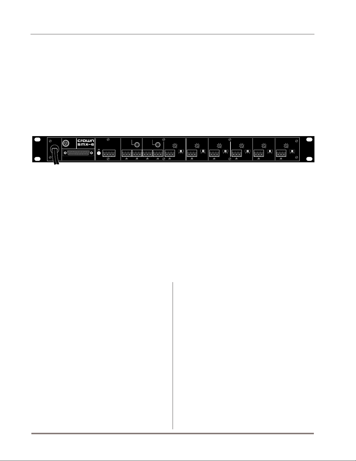
1.1 Three Mixer / Multiplexer Models ............................ 6
2.1 Front and Rear Panels.............................................. 8
3.1 An
3.2 RS232 Cable Wiring for a PC ..................................11
3.3 RS422 Cable Wiring for a Macintosh ......................11
3.4 RS232 Cable Wiring for a Macintosh ......................11
3.5 Selecting the Communication Parameters ..............12
3.6 Crown Bus Wiring for Removable Barrier Blocks... 13
3.7 Crown Bus Wiring for 5-pin DIN Input ....................14
3.8 Crown Bus Wiring for 4-pin DIN Output ................. 14
3.9 Crown Bus Wiring Loopš from Output to Input, etc.14
3.10 An Audio Input Section............................................15
3.11 Suggested Audio Input Gain Control Settings........15
3.12 Balanced Audio Input Wiring...................................15
3.13 Unbalanced Audio Input Wiring ..............................16
3.14 Sensing Input Section.............................................. 16
3.15 An Audio Output Section .........................................17
3.16 Balanced Audio Output Connections
3.17 Unbalanced Audio Output Connections
3.18 A 12x2 Mixer Using 2 Mixer/Multiplexers
3.19 Stacking the Outputs of Multiple Units ................... 18
3.20 A 6x8 Mixer Using 4 Mixer/Multiplexers................. 18
3.21 Paralleling the Inputs of Multiple Units
3.22 A 12x8 Mixer Using 8 Mixer/Multiplexers
3.23 Sample Auxiliary System Wiring
3.24 Internal Auxiliary Circuit
4.1 A Crown Local Net RS422 Serial Loop
4.2 Crown Local Net Wiring
6.1 General IQ Mixer Block Diagram
A.1 IQ Address Switch Settings from 0 to 125.............. 27
A.2 IQ Address Switch Settings from 126 to 250..........28
IQ System
ILLUSTRATIONS
with a PC Host Computer, etc. ........10
......................
..................
...............
...................
...............
.............................
..........................................
....................
...........................................
............................
17
17
17
18
18
19
19
20
21
25
Rev. 0
Page 5
Page 6
IQ Mixer/Multiplexer Hardware Installation
ENABLEDSPI
ENABLEDSPI
Fig. 1.1 Three Mixer / Multiplexer Models
Page 6
Rev. 0
Page 7

IQ Mixer/Multiplexer Hardware Installation
1 Welcome
Thank you for purchasing a Crown IQ mixer/multiplexer. IQ mixer/multiplexers are intelligent mixers
with special signal routing capabilities. Their intelligence stems from a powerful onboard microprocessor which enables them to be controlled and
monitored by a Crown
IQ System
each output can be individually controlled and, with
their
distributed intelligence
operate even when an
IQ System
In addition to two main outputs (one for each channel), each model has a second set of ÷busš outputs
which are switched on/off by a relay. This enables
many mixer/multiplexers to be connected to a common audio bus without loading it down. They are
designed to work as stand-alone units in a small
audio system or as modules in a large audio system.
Three different models are available to serve a wide
variety of needs. The
MPX-6
operate as 6x2 mixers. The
as a 5x2 mixer. Multiple units can be connected
together to form larger mixers. For example, a
6
and
SMX-6
can be connected together to form a
single 12x2 mixer. They can also be connected as a
6x4 mixer.
®
. Each input and
™
capability, continue to
is not connected.
™
and
SMX-6
AMB-5™
™
models
can operates
MPX-
1.1 Options
In a standard
the mixer/multiplexers are connected to the system
via the Crown Bus. The Crown Bus is a serial communication loop which carries IQ commands and
data. IQ mixer/multiplexers are also able to bypass
the Crown Bus and connect (one at a time) directly
to a computer (PC compatible or Macintosh®). Once
configured, the mixer/multiplexers can be disconnected and allowed to operate by themselves.
Option 1 allows an
nect to a host computer and serve as a Crown Bus
interface between the computer and other IQ components. This eliminates the need to purchase a
separate IQ interface (IQ-INT) for a small
tem
.
Option 4 allows an
Crown Local Net loop. The Crown Local Net is a
communication subsystem within an
Using it, two or more
between themselves to keep track of the total number of open microphones. This information can then
be used to prevent feedback when more mics are
open.
Note: Options 2-3 are not presently available.
IQ System
AMB-5, MPX-6
SMX-6
, the IQ components like
or
SMX-6
to con-
IQ Sys-
(only) to connect to a
IQ System
SMX-6s
can communicate
.
The
MPX-6
is the simplest of the three models. It
provides basic mixing capabilities. All control and
monitor functions are handled by the
The
MPX-6
does not have the automatic mixing
IQ System
capability of the other models because it does not
have input sensing.
The
SMX-6
sensing
is more sophisticated because it has
ability. A sensing circuit is located at the
beginning of each input to sense the input signal
level ahead of any signal processing. Similar sensors are located at each output. These sensors,
along with its onboard intelligence, enable the
6
to perform many versatile functions like automatic
SMX-
mixing, compression, and automatic level control.
The
AMB-5
has the same functions as an
SMX-6
plus it has the ability to sense the ambient sound
level and automatically adjust its output level accordingly. In this way it serves as the ultimate
automatic level controller. Input 6 is dedicated as
the sensing input, leaving five to function normally
as a 5x2 mixer. Unlike the
SMX-6
, signal processing
is only available for Channel 1. Channel 2 functions
like an
MPX-6
.
.
1.2 Unpacking
Please unpack and inspect the unit for any damage
that may have occurred during transit. If any damage is found, notify the transportation company immediately. Only you, the consignee, may initiate a
claim with the carrier for damage resulting from
shipment. Crown will cooperate fully as needed.
Save the shipping carton as evidence of damage for
the shipper’s inspection.
Even if the unit arrived in perfect condition, as most
do, save all packing materials so you will have them
if you ever need to transport the unit. NEVER SHIP
THE UNIT WITHOUT THE FACTORY PACK.
Rev. 0
Page 7
Page 8
(Front View)
IQ Mixer/Multiplexer Hardware Installation
120 VAC
60 Hz
20 W
AUX
CTRL
RS232 / RS422
CROWN BUS
SERIAL DATA LOOP
IN
OUT IN
+–+
INPUT
GROUND
ONLY
–
AUDIO
OUT
2
MAIN
STACK
IN
BUS
AUDIO
OUT
1
MAIN BUS
STACK
IN
(Rear View)
Figure 2.1 Front and Rear Panels
2 Facilities
AUX Connector
A 3-pin male mini-XLR connector is used for remote
control of equipment lacking the Crown Bus. A 10
VDC power source is provided to control solid state
relays and other logic circuits. The auxiliary connector also includes a high-impedance 10 VDC input. (Section 3.4)
Stack Audio Inputs
These two stack inputs allow you to multiply the
number of audio inputs by stacking 2, 3, or more
units to build a 12x2, 18x2, or larger mixer. (Section
3.3.3)
DSPI
This yellow LED is a Data Signal Presence Indicator.
It flashes whenever a valid IQ command has been
received. The indicator can also be forced on to aid
rapid troubleshooting of the Crown Bus wiring.
AUDIO
IN
6
+–+–+–+–+–
AUDIO
ADD 25
0
5
FOR MIC
IN
-5
10
-10
15
5
21
-12
LMP
+– +– +– +– +–
AUDIO
ADD 25
0
5
FOR MIC
IN
-5
10
-10
-12
-10
15
4
21
LMP
AUDIO
ADD 25
0
5
FOR MIC
IN
-5
10
15
3
21
-12
LMP
AUDIO
ADD 25
0
5
FOR MIC
IN
-5
10
-10
15
2
21
-12
LMP
AUDIO
ADD 25
0
5
FOR MIC
IN
-5
-10
-12
-5
10
-10
15
1
21
-12
LMP
Enable Indicator
This amber enable indicator shows that the unit is
receiving AC power.
Audio Input Gain Control
Each of the six input channels has a screwdriverset, calibrated gain potentiometer for adjusting the
input gain to the input signal level. They can be
used to compensate for different microphone sensitivities. (Section 3.3.1)
RS232/RS422 Connector
This DB25 connector functions as a standard RS232
or RS422 serial communications port. It can be used
for connection directly to a host computer (Section
3.1) or, if Option 4 was purchased, for connection to
a Crown Local Net loop (Section 4.2).
Crown Bus Ground Connector
This chassis ground stud is provided to connect an
ADD 25
0
5
FOR MIC
10
15
21
LMP
Page 8
Rev. 0
Page 9

IQ Mixer/Multiplexer Hardware Installation
Important:
(H) connectors. TURN THE UNIT OFF before changing the settings of the IQ Address (M),
Baud Rate & Parity (N) or Communication Standard (O) switches.
optional shield for the Crown Bus cable. Only the
shield of the input cable should be connected.
Shielded wire will reduce the total distance a Crown
Bus loop can be run, but shielding may be necessary to reduce interference with certain kinds of
audio cables. (Section 3.2)
TURN THE UNIT OFF before connecting to the RS232/RS422 (F) or Crown Bus
Crown Bus Input/Output Connector
A 4-pin removable barrier block plug is used for
input and output connection to the Crown Bus. The
pins are numbered backward from right to left (as
you face the back panel of the unit). Pin 1 is input
negative (–), pin 2 is input positive (+), pin 3 is
output negative (–), and pin 4 is output positive (+).
(Section 3.2)
Main Audio Outputs
A 3-pin removable barrier block plug is used to
connect to the main output of each channel. These
outputs can also be connected to the stack inputs
(B) of other mixer/multiplexers to make a 12x2 (or
larger) mixer. (Section 3.3.2)
Auxiliary Bus Audio Outputs
A 3-pin removable barrier block plug is used to
connect to the bus audio output of each channel.
The bus outputs are isolated switchable outputs that
can be turned on when needed by the
This allows many multiplexers to be tied together on
the same bus without loading down the outputs.
(Section 3.3.2)
IQ System
Audio Inputs
A 3-pin removable barrier block plug is used to
connect to the input of each of the six audio inputs.
The input gain control (E) and the input selector (K)
of each one should be set to match the input signal
level. These inputs can also be connected in parallel
with the inputs of other mixer/multiplexers to make a
6x4 (or larger) mixer. (Section 3.3.1)
Input Selector
A three-position input selector accommodates different input signal levels. The three settings are L
for line-level input, M for mic-level input, and P for
mic-level input with phantom power. The P setting
supplies 44 volts DC for phantom-powered mics.
IQ Address
An 8-section DIP switch is used to set the IQ address of the unit. The unit must be given a unique IQ
address so it can be independently controlled and
monitored by a the system. It must also be set
properly if the unit is to be used in a Crown Local
Net. Two or more IQ components of the same type
should NEVER have the same address on the same
Crown Bus loop. (Section 3.2) Important: The IQ
address should only be set with the power cord
disconnected from the AC supply.
Baud Rate & Parity
A 6-section DIP switch is used to set the baud rate
and parity for RS232/RS422 serial communication.
This is only necessary when the DB25 connector (F)
is used. Important: The baud rate should only be set
with the power cord disconnected from the AC sup-
.
ply.
Communication Standard
A communication standard switch which allows the
unit to be configured for the RS232 or RS422 communications. (Sections 3.1³3.1.1) Important: The
communication standard should only be set with the
power cord disconnected from the AC supply.
Rev. 0
Page 9
Page 10

RS232
IQ Mixer/Multiplexer Hardware Installation
ENABLEDSPI
ENABLE
ODEP
CH1 CH2
CH1 CH2
CH1 CH2
IOC
SPI
ODEP
IOC
SPI
ODEP
IOC
SPI
POWER
OFF
ENABLE
POWER
OFF
ENABLE
POWER
OFF
Fig. 3.1 An IQ System with a PC Host Computer and Two Mixer/Multiplexers
3 Hardware Installation
The installation of an IQ mixer/multiplexer consists
of two major parts: installing the hardware and configuring the software. This manual deals only with
hardware installation. Refer to the appropriate software manual for instructions in setting up and operating your unit.
Provide adequate cooling if the unit will be used in a
hot environment. Allow one empty rack space (1.75
inches or 4.4 cm.) between each unit if more than
four units will be stacked in a cabinet. Each empty
rack space should be sealed with a blank rack
panel.
The hardware installation is divided into 4 steps:
1) connecting to a host computer, 2) connecting to
the Crown Bus, 3) connecting the audio inputs and
outputs and 4) connecting auxiliary devices.
3.1 Connecting to a Host Computer (Step 1)
An IQ host computer is an IBM® PC compatible or
Apple® Macintosh computer which is used to configure or control/monitor part or all of an
Depending upon the design of your
may or may not require a host computer during
normal operation.
IQ System
IQ System
, it
ENABLEDSPI
ENABLE
ODEP
CH1 CH2
CH1 CH2
IOC
SPI
ODEP
IOC
SPI
POWER
OFF
ENABLE
POWER
OFF
CROWN BUS LOOP 1
ENABLE
ODEP
CH1 CH2
IOC
SPI
POWER
OFF
CROWN BUS LOOP 2
How the mixer/multiplexer will be used will determine whether or not it will need to be connected
directly to a host computer. If the unit will be connected to the Crown Bus it will not need to be
connected directly to a host computer. The following
circumstances require connection to a host computer:
• If a Crown Bus will not be used, the mixer/multiplexer will need to be connected to a host
computer so the software inside the unit can
be configured. Afterward, if manual control is
not required, the host computer can be disconnected.
• If the mixer/multiplexer must be configured before it is installed into an IQ System, it must be
connected directly to a host computer for configuration. The onboard battery of the unit will
maintain its software configuration for up to 60
days without it being plugged into an AC
source.
• If the mixer/multiplexer will be used as an IQ
interface (Option 1) it will need to be con-
.
nected directly to a host computer.
One of the advantages of connecting directly to a
host computer is that a separate IQ interface (IQINT) is not required. If you plan to configure the unit
Page 10
Rev. 0
Page 11

IQ Mixer/Multiplexer Hardware Installation
(+)
131
2514
12
34 5
678
Output handshake
Input handshake
Transmit data –
Ground
Receive data –
Not used
1
2
3
4
5
4
5
2
7
3
Clear to Send (CTS)
Request to Send (RTS)
Receive Data (RXD)
Signal Ground (GND)
Transmit Data (TXD)
PIN PIN
Cable connectors are numbered as they appear from the front.
Macintosh
(RS232)
SMX-6 (RS232)
6,7,8
while it is connected to the Crown Bus, skip ahead
to Section 3.2.
There are two main communication standards supported by the unit for serial communication with a
host computer. They are RS232 and RS422.
RS232 is commonly used with IBM PCs and compatibles. Because it uses unbalanced signal wiring,
it cannot be used for distances over 50 feet (15.2
m).
RS422 is commonly used with Macintosh computers. It uses balanced signal wiring and can be used
for distances up to 2,000 feet (610 m).
Although uncommon, RS423 communication can
also be used. It uses the unbalanced transmitter
(TXD) wiring of RS232 and the balanced receiver
(RXD) wiring of RS422 to provide signal ground
isolation between the transmit and receive lines.
With a proper cable it can be used over a greater
distance than RS232…but a shorter distance than
RS422. For details contact either Crown Tech. Support or Amcron Tech. Services (see page 22).
The following illustrations show how to wire the two
most common serial cables:
PC (RS232) SMX-6 (RS232)
51
96
Cable connectors are numbered as they appear from the front.
ReceiveData (RXD)
Not used
Transmit Data (TXD)
Signal Ground (GND)
Request to Send (RTS)
Clear to Send (CTS)
PIN PIN
1,4,6,9
2
3
5
7
8
3
Transmit Data (TXD)
2
Receive Data (RXD)
7
Signal Ground (GND)
4
Clear to Send (CTS)
5
Request to Send (RTS)
Fig. 3.2 RS232 Cable Wiring for a PC
Macintosh
(RS422)
678
34 5
12
Cable connectors are numbered as they appear from the front.
Output handshake
Input handshake
Transmit data –
Ground
Receive data –
Transmit data +
Not used
Receive data +
Fig. 3.3 RS422 Cable Wiring for a Macintosh
Rev. 0
PIN PIN
1
2
3
4
5
6
7
8
SMX-6 (RS422)
4
5
2
7
3
10
9
Clear to Send (CTS)
Request to Send (RTS)
Serial In (–)
Signal Ground (GND)
Serial Out (–)
Serial In (+)
Serial Out
131
2514
131
2514
It is also possible to use RS232 to communicate
with a Macintosh computer. Here’s how to wire the
cable:
Fig. 3.4 RS232 Cable Wiring for a Macintosh
Important: Do not use twisted-pair wire for RS232
because it increases crosstalk. Instead use an untwisted cable or ribbon cable. Twisted-pair wire can
be used for RS422.
3.1.1 Communication Standards and Parameters
Before communication can take place between the
unit and a host computer the communication standard must be selected and the communication parameters must be set with switches accessed
through an opening in the side of the chassis. (Figures 2.2 and 3.5)
Caution: Be sure to disconnect the AC power from
the unit before selecting a different communication
standard or changing the parameters.
IBM PC-compatible computers typically have an
RS232 serial port, so the communication standard
switch should be moved to the right (Figure 3.5).
With a Macintosh host computer, the standard is
usually RS422, and the communication standard
switch should be moved to the left. In the rare event
that RS423 communication is used, set the switch to
the RS422 position.
Setting the communication parameters for RS232
and RS422 serial communication is accomplished
using the six segment baud rate and parity DIP
switch in Figure 3.5. The first four switches select
the baud rate and the last two set the parity. Use the
fastest baud rate possible. The highest baud rate
supported by the unit is 19.2 K baud. Parity checking is not presently supported and should be OFF.
The odd/even parity bit doesn’t matter when parity
is switched OFF. The unit has been factory set to 1
stop bit and 8 data bits.
Important: The communication standard and param-
Page 11
Page 12

IQ ADDRESS
1248163264
12345678
128
OFF
ON
BAUD RATE
& PARITY
BAUD RATE PARITY
123456
COM
STANDARD
RS232RS422
PCMAC
IQ Mixer/Multiplexer Hardware Installation
BAUD RATE & PARITY SETTINGS
123456
19200
9600
BAUD
RATE
PARITY
4800
2400
1200
300
150
ON
OFF
ODD
EVEN
Fig. 3.5 Selecting the Communication Standard and Parameters
eters of the mixer/multiplexer and the host computer
must be the same. Any mismatch will prevent communication from taking place.
The communication parameters of the host computer are set by the IQ software. This is true for both
PCs and Macintosh computers. Please refer to the
appropriate software manual for details.
Here are some important guidelines when configuring serial communication:
• Use the same communication
standard
at each
end. If the unit is set for RS232, the computer
must also be set for RS232. (Refer also to the
appropriate IQ software manual.)
• Use the same communication
parameters
at
each end. The unit and the computer must be
set for the same baud rate and parity checking.
• Use the highest baud rate possible but be
aware that
in some PCs cannot function over 9600 baud
the communication circuitry (UART)
.
(IQ mixer/multiplexers can be set as high as
19.2 K baud.)
• If the host computer fails to communicate with
the unit and the communication standard and
parameters are set correctly, try reducing the
baud rate of both the unit and the computer.
• If communication problems persist, check the
serial cable for improper wiring or possible
shorted or broken wires.
• For further assistance call either the Crown
Technical Support Group or Amcron Technical
Services Dept. (see page 22 for telephone
numbers).
3.2 Connecting to the Crown Bus (Step 2)
The Crown Bus is a serial communication loop designed to transmit IQ commands and data. As a
communication standard it is independent of the
wiring system used. This flexibility is a great
strength, enabling a Crown Bus loop to be wired
with either fiber optic cabling or with inexpensive
twisted-pair wire, whichever the installation requires. A single
Crown Bus loop. To function properly, a Crown Bus
loop must be unbroken.
3.2.1 Setting the IQ Address
Before installing a mixer/multiplexer on a Crown
Bus loop, it must be given a unique IQ address.
This address will be used by the
ever it communicates with the unit.
The 8-segment DIP switch shown in Figure 3.5 is
used to set the IQ address. No two IQ components
of the same model which are connected to the same
IQ System
can have more than one
IQ System
when-
Page 12
Rev. 0
Page 13

IQ Mixer/Multiplexer Hardware Installation
PIN
1
2
3
4
PIN
1
2
3
4
Input (–)
Input (+)
Output (–)
Output (+)
Input (+)
Input (–)
Cable connectors are numbered as they appear from the front.
1234
Mixer/Multiplexer 1
Output (–)
Output (+)
1
2
34
Mixer/Multiplexer 2
GNDGND
Optional Shield
Crown Bus can have the same address. Suppose,
for example, an
loops as shown in Figure 3.1 and an
IQ System
has two Crown Bus
SMX-6
is
installed in loop 1 and given IQ address 77. No
other
SMX-6
Crown Bus loop 1. However, an
can be given the same address in
SMX-6
can have the
same address if it is installed in loop 2. Different IQ
components can have the same address and be in
the same Crown Bus loop. In the previous example,
an
AMB-5
address 77 because it is not an
could be installed in loop 1 and use IQ
SMX-6
.
A valid IQ address is any number from 1 to 250. Do
not use a number higher than 250 since they are
reserved for special use. An address of ÷0š (zero)
should not be used. The IQ address is determined
by adding the values of each segment of the DIP
switch which is turned on (pushed down). Figure 3.5
shows the value of each DIP switch segment. For
example, if the desired unit address is 1, only
switch 1 should be down. If the desired unit address
is 217, switches 8, 7, 5, 4, and 1 should be down
(128+64+16+8+1=217). See Appendix A for list of
all valid DIP switch settings.
If the IQ interface used is an IQ-INT, the system can
have up to eight separate Crown Bus loops. This will
enable the audio system to be divided into different
zones, each with its own Crown Bus loop. Dividing
the
IQ System
into multiple Crown Bus loops has
advantages and disadvantages which are listed below:
Multiloop Advantages
• A break in communication in one loop does not
affect other loops.
• Over 250 IQ components of the same model
can be use in a system.
• The same IQ address can be used more than
once (once per loop per model).
vices (see page 22) for information on adding the
appropriate transceivers.
Here are some guidelines for twisted-pair wiring:
• Use shielded twisted-pair wire at least 26
AWG in size. The wire should be of good quality and should NOT have high capacitance (30
picofarads/foot or less is good). Shielded wire
is recommended for situations where interference is a problem. (West Penn 452 or an
equivalent wire works well.) The shield serves
two purposes: First, it helps prevent the IQ
data signal from transmitting to nearby audio
wiring. Second, it helps prevent outside RF
from interfering with the data signal. However,
in most cases interference is not a problem
and, since unshielded wire has lower capacitance, it is a better choice.
• If shielded wire is used, connect the shield
only to the input connector.
• Add an IQ Repeater for very long
loops…greater than 1,000 feet (305 m)…or
when required by high-capacitance wire. Although we recommend adding a repeater for
loops longer than 1,000 feet, it is often possible to go 2,000 feet (610 m) or more. The
most significant characteristic of the wire is its
capacitance. The lower the capacitance, the
longer the loop can be. Unshielded wire typically has less capacitance.
• Never use the ground wire in a mic snake
line.
It may sometimes be convenient to run
Crown Bus data signals to and from stage
monitor amplifiers along unused wire pairs in a
mic snake. If this is done, do not use the
ground wire which is normally connected to pin
1 on an XLR connector or data noise will be
Single Loop Advantages
• The
IQ System
can send and retrieve data
faster in a single loop.
• ÷Real timeš level display of a greater number
of units is possible.
3.2.2 Crown Bus Wiring
The Crown Bus is implemented in IQ mixer/multiplexers as a 20 milliamp current loop operating at
38.4 K baud so that it can function with inexpensive
twisted-pair wiring. If fiber optic wiring is required
contact Crown Tech. Support or Amcron Tech. Ser-
Rev. 0
Fig. 3.6 Crown Bus Wiring for Removable Barrier Blocks
Page 13
Page 14

IQ Mixer/Multiplexer Hardware Installation
Crown Bus Barrier Block
Crown Bus 5-pin DIN Input
5
1234
The Crown Bus connector
shown here is the standard
connector found on the back
panel of most mixers and SLM.
PIN
Output (+)
Output (–)
Input (+)
Input (–)
GND
1
2
3
4
The female Crown Bus connector shown
here can be found on the back panel
Optional Shield
4
3
of IQ-INT IIs and most IQ-P.I.P.s.
PIN
5
4
3
2
1
Fig. 3.7 Crown Bus Wiring for 5-pin DIN Input
IQ
POWER
OUT
2
IN
OUT
1
IN
INTERFACE
CROWN BUS
120 VAC
AUX
SERIAL DATA LOOP
60 Hz
CTRL
OUT IN
–
+
–
AUX
CTRL
AUX
CTRL
RS232 / RS422
RS232 / RS422
RS232 / RS422
+
CROWN BUS
SERIAL DATA LOOP
OUT IN
–
+
CROWN BUS
SERIAL DATA LOOP
OUT IN
–
+
–
+
–
+
MULTIPLEXERS
MIC/LINE MIXER/
20 W
120 VAC
60 Hz
20 W
120 VAC
60 Hz
20 W
1
2
(Not Used)
(Not Used)
GND
Input (+)
Input (–)
TO HOST COMPUTER
IN
OUT
6
IN
OUT
5
IN
OUT
4
IN
OUT
3
IN
IQ INTERFACE
AUDIO
ADD 25
AUDIO
0
5
ADD 25
AUDIO
0
5
FOR MIC
STACK
AUDIO
STACK
AUDIO
IN
IN
OUT
OUT
1
2
MAIN BUS
BUS
MAIN
+–
+–
+–
+–
STACK
AUDIO
STACK
AUDIO
IN
IN
OUT
OUT
1
2
MAIN BUS
BUS
MAIN
+–
+–
+–
+–
STACK
AUDIO
STACK
AUDIO
IN
IN
OUT
OUT
1
2
MAIN BUS
BUS
MAIN
+–
+–
+–
+–
IN
6
+–
AUDIO
IN
6
+–
AUDIO
IN
6
+–
IN
-5
0
5
FOR MIC
IN
-5
10
-5
10
-10
-10
15
4
-10
-12
-5
-10
-12
-5
-10
-12
21
15
-12
5
21
-12
21
LMP
LMP
+–
+–
AUDIO
ADD 25
AUDIO
0
5
ADD 25
0
5
FOR MIC
IN
-5
0
5
FOR MIC
IN
-5
10
10
-10
-10
15
4
21
15
-12
5
21
-12
21
LMP
LMP
+–
+–
AUDIO
ADD 25
AUDIO
0
5
ADD 25
0
5
FOR MIC
IN
-5
0
5
FOR MIC
IN
-5
10
10
-10
-10
15
4
21
15
-12
5
21
-12
21
LMP
LMP
+–
+–
SERIAL OUT
Crown Bus 4-pin DIN Output
4
3
2
The female Crown Bus connector shown
here can be found on the back panel
of IQ-INT IIs and most IQ-P.I.P.s.
PIN
(Not Used)
(Not Used)
Output (+)
Output (-)
4
3
2
1
Fig. 3.8 Crown Bus Wiring for 4-pin DIN Output
OUT
8
IN
OUT
7
ADD 25
FOR MIC
10
15
LMP
ADD 25
FOR MIC
10
15
LMP
ADD 25
FOR MIC
10
15
LMP
AUX
AUDIO
IN
3
+–
AUDIO
IN
3
+–
AUDIO
IN
3
+–
SERIAL IN
COMPUTER
ADD 25
AUDIO
ADD 25
AUDIO
0
5
FOR MIC
ADD 25
0
5
FOR MIC
IN
-5
0
5
FOR MIC
10
IN
-5
10
-5
10
-10
15
-10
15
1
-10
-12
-5
-10
-12
-5
-10
-12
DSPI
21
15
-12
2
21
-12
21
LMP
LMP
LMP
+–
+–
ADD 25
AUDIO
ADD 25
AUDIO
0
5
FOR MIC
ADD 25
0
5
FOR MIC
IN
-5
0
5
FOR MIC
10
IN
-5
10
10
-10
15
-10
15
1
21
15
-12
2
21
-12
21
LMP
LMP
LMP
+–
+–
ADD 25
AUDIO
ADD 25
AUDIO
0
5
FOR MIC
ADD 25
0
5
FOR MIC
IN
-5
0
5
FOR MIC
10
IN
-5
10
10
-10
15
-10
15
1
21
15
-12
2
21
-12
21
LMP
LMP
LMP
+–
+–
BALANCED INPUTS
CH–1
CH–2
3
INVERT
NON-
(–)
INVERT
(+)
1
2
GND
1
panel of most mixers and SLM.
Optional Shield
Important: Provide adequate cooling if the unit
will be used in a hot environment. Allow one
empty rack space (1.75
inches or 4.4 centimeters) between each unit if
CROWN BUS
more than four units will
be stacked in a cabinet.
Each empty rack space
should be sealed with a
blank rack panel to facilitate proper air flow inside
the cabinet.
Crown Bus Barrier Block
1234
The Crown Bus connector
shown here is the standard
connector found on the back
PIN
1
Output (+)
2
Output (–)
3
Input (+)
4
Input (–)
GND
Page 14
IQ–P.I.P. MODULES
AMPLIFIERS WITH
Figure 3.9 Crown Bus Wiring ÷Loopsš from Output to Input of Each IQ Component
SERIAL OUT
SERIAL OUT
SERIAL IN
DSPI
AUX
SERIAL IN
3
INVERT
NON-
(–)
INVERT
(+)
1
2
GND
BALANCED INPUTS
CH–1
CH–2
3
INVERT
NON-
(–)
INVERT
(+)
1
2
GND
BALANCED INPUTS
CH–1
CH–2
DSPI
AUX
Rev. 0
Page 15

IQ Mixer/Multiplexer Hardware Installation
Pro audio
equipment
Semi-pro or
consumer
equipment
Dynamic
mic, speech
Condenser
mic, speech
Hot
condenser
mic, speech
Dynamic
mic, music
Hot
condensor
mic, music
Close-miked
dynamic mic,
bass/drums
Close-miked
dynamic mic,
kick drum,
guitar amp
dBm/dBV
dBu
Suggested
Setting
+4 dBm
+4 dBu
–4 (L)
–10 dBV
–8 dBu
+8 (L)
–75 dBV
–73 dBu
+21 (M)
–65 dBV
–63 dBu
+11 (P)
–45 dBV
–43 dBu
+18 (P)
–55 dBV
–53 dBu
+21 (M)
–25 dBV
–23 dBu
–2 (P)
–15 dBV
–13 dBu
–12 (M)
–5 dBV
–3 dBu
–12 (M)
or
+3 (L)
0 dBm = 0.775 VRMS with a 600 ohm load, 0 dBV = 1 VRMS, 0 dBu = 0.775 VRMS
added to the audio lines. Use only the signal
lines which normally connect to pins 2 and 3 of
the XLRs.
Note: Because typical mic cables
have high capacitance, the maximum possible
Crown Bus loop distance will be less.
Outside RF interference is seldom a problem for a
Crown Bus loop…especially if shielded twisted-pair
wire is used. However, there are extreme situations
when fiber optic wiring is recommended. For example, locating a Crown Bus loop next to an AM
radio transmission line may require fiber optic cabling. An extremely long Crown Bus loop distance
(greater than 10 miles) may also require fiber optic
cabling.
Some examples of twisted pair wiring follow. Figure
3.6 shows point-to-point wiring for the Crown Bus
using two female removable barrier block connectors:
Some IQ components use separate 5-pin and 4-pin
DIN connectors for Crown Bus input and output
wiring. Connecting to them is shown below:
The IQ components in each Crown Bus loop are
wired in series. The output of one IQ component
÷loopsš to the input of the next and so on. This is
shown in Figure 3.9.
3.3 Connecting the Audio Ins & Outs (Step 3)
IQ mixer/multiplexers have 6 mic/line inputs and
2 stack inputs. (Input 6 of the
for ambient sensing and is discussed in Section
3.3.2.) For output, there are two audio channels that
feed two main and two auxiliary bus outputs.
3.3.1 Mic/Line Inputs
Three-terminal removable barrier block connectors
are provided for the audio inputs. Each input has an
input selector switch. Slide it to the left (M) for
microphone signal levels up to +7 dBu (0 dBu =
Microphone
Note: If more than one
input is driven from the same
Floating
source
Output
source equipment, connect only
one shield at the source
–
equipment chassis.
+
2-wire line cord
(or battery power)
AMB-5
Shield connected
at both ends
INPUT
INPUT
is dedicated
+–
+–
AUDIO
IN
1
-10
ADD 25
0
5
FOR MIC
-5
10
15
21
-12
LMP
+–
Fig. 3.10 An Audio Input Section
Rev. 0
Fig. 3.11 Suggested Audio Input Gain Control Settings
Grounded
source
Shield not connected
at this end
–
Output
+
3-wire grounded line cord
(or other ground connection)
Fig. 3.12 Balanced Audio Input Wiring
INPUT
+–
Page 15
Page 16

IQ Mixer/Multiplexer Hardware Installation
0.775 volts). Select the center position (L) for line
level signals up to +32 dBu. Slide it to the right (P)
to provide 44 VDC to mics requiring phantom
power.
Each input has a screwdriver-set, calibrated gain
control to compensate for different input source
levels. The slot on the control shaft points to the
gain setting. The settings are labelled for line-level
input. Add 25 dB to the scale if the inputs are
switched for microphone level signals.
Use a screwdriver to adjust the gain pot so that the
input signal level plus gain equals roughly 0 dBu.
You will need to know, or estimate, the level of the
input source. Setting the source signal level to approximately 0 dBu will provide 20 dBu of headroom
in the input preamp. Some recommended settings
follow in Figure 3.11:
Floating
source
Output
+
Grounded
source
Output
+
Floating
source
Output
+
Shield connected
to ground terminal
2-wire line cord
(or battery power)
Shield not connected
at this end
3-wire grounded line cord
(or other ground connection)
Shield connected to both negative
(–) and ground input terminals
INPUT
INPUT
+–
+–
Twin-lead shielded cable
Figures 3.12-13 show the normal wiring for balanced and unbalanced inputs. It is also possible to
parallel the inputs of multiple units to increase the
number of mixer outputs. For example, the inputs of
two 6x2
MPX-6s
can be paralleled to create a 6x4
mixer. This technique is described in Section 3.3.6.
Balanced sources should be wired as shown below
in Figure 3.12. Notice that the shield is not connected to the chassis ground of the source if the
source is also connected to the AC ground (that is,
it has a grounded AC plug). This prevents unwanted
ground loops.
Unbalanced sources should be wired as shown
below in Figure 3.13. The examples in Figure 3.13
are grouped according to whether twin-lead
shielded wire or single-conductor coax (and twisted
pair) wire is used.
3.3.2
AMB-5
Ambient Sensing Input
SENSE
IN
ADD 25
0
5
FOR MIC
-5
10
-10
15
21
-12
LMP
+–
Fig. 3.14 Sensing Input Section
In addition to its automatic mixing capabilities, the
AMB-5
also has the ability to adjust the output level
of Channel 1 to the ambient sound level. (Remember, Channel 2 functions only as an
MPX-6
.) It does
this with its sensing input (input 6). This is an
extremely useful feature. With an
AMB-5
the paging
level at a train station can be automatically adjusted
so pages can be heard over the roar of an incoming
train and yet quieted to an appropriate level during
periods of softer ambient sound levels.
Grounded
source
Output
+
Page 16
2-wire line cord
(or battery power)
3-wire grounded line cord
(or other ground connection)
INPUT
+–
Input ground
terminal not used
INPUT
+–
Fig. 3.13 Unbalanced Audio Input Wiring
The sensing input section of the back panel is
shown in Figure 3.14 below. It has the same features as the other mic/line inputs: input gain control
and input level switch.
The obvious way to use the sensing input is to
connect a microphone (such as a Crown PZM-6D) to
it and locate the microphone so that it can accu-
or twisted pair
rately receive the ambient sound level. Great care
Single-conductor coax
must be taken in the placement of the ambient sensing microphone so that it is not too close to the
loudspeakers being driven by the system. If it is too
close, the system could go into feedback oscillation.
Rev. 0
Page 17

IQ Mixer/Multiplexer Hardware Installation
It is also possible to connect more than one ambient
sensing microphone to the sense input. This can be
accomplished by taking advantage of the manual
mixing function of Channel 2. Simply connect each
ambient sensing microphone to one of the five regular inputs of the
AMB-5
and use the IQ software to
assign each of them to Channel 2 only. Switch the
sense input to the line-level position (L) and connect
the main audio output of Channel 2 to it. Use the IQ
software to control the level of the ambient sensing
microphones. The microphones which are located in
more critical areas can be set to a higher level so
they will trigger the level controller first.
Be sure the microphone has adequate sensitivity for
the spectral content of the ambient sound. For example, a microphone with a bandwidth designed
solely for speech reinforcement may not have adequate low-frequency sensitivity to pick up the lowfrequency noise of machinery in a factory.
3.3.3 Audio Outputs
Three-terminal removable barrier block connectors
are provided for audio output (Figure 3.15). Both a
main and bus output are provided for each of the
two mixer channels. They are balanced and can
drive 1200 ohms or more to +26 dBu or 600 ohms to
+20 dBu. Each bus output can drive any number of
inputs within this impedance range.
The main audio outputs are provided for connection
with other audio equipment such as power amplifiers. They can also be stacked with the outputs of
other mixer/multiplexers to increase the number of
mixer inputs. For example, two 6x2
MPX-6s
can be
stacked to create a 12x2 mixer. This is described in
Section 3.3.4.
The bus outputs are turned on or off by relays and
function like the aux send outputs on a conventional
mixing console. They are switched on or off by the
IQ System
. This special design allows many bus
outputs to be connected to a common audio bus in a
multiple-zone network (like a large airport paging
system). Because the bus outputs are controlled by
the
IQ System
, they can be kept off until they are
actually used, preventing too many of them being
on at the same time and loading down a common
audio bus network.
The versatile bus outputs can be used for any audio
system, small or large, where switchable outputs
are desired, such as switchable recording outputs.
Both main and bus outputs are wired the same way.
Balanced output wiring is shown below.
Notice that the shield is not connected to the output
ground terminal if the load is connected to AC
ground. This prevents unwanted ground loops. Unbalanced output wiring is shown next.
Shield connected at both ends
Floating
load
+
Output
–
OUTPUT
+–
Shield not connected
at this end
2-wire line cord
(or battery power)
Grounded load
(power amp)
+
Output
–
OUTPUT
+–
Fig. 3.16 Balanced Audio Output Connections
OUTPUT
3-wire grounded line cord
(or other ground connection)
Twin-lead shielded cable
Shield connected to ground
terminal of load only
+
Load
Output
+–
Rev. 0
AUDIO
OUT
1
STACK
IN
MAIN BUS
+–+–
Fig. 3.15 Audio Output Section
Single-conductor coax
or twisted pair
OUTPUT
Load
+
Output
+–
Fig. 3.17 Unbalanced Audio Output Connections
Page 17
Page 18

IQ Mixer/Multiplexer Hardware Installation
3.3.4 Stack Inputs
The stack in jacks (Figure 3.15) enable the audio
inputs to be increased by stacking 2, 3, or more
mixer/multiplexers to create a 12x2, 18x2 or wider
mixer. Use 2-conductor shielded cable to route the
signal from the main output of one unit to the stack
input (RCA phono jack) of the second unit. This is
shown in Figure 3.19. The stack input routes the
signal directly to the output of the second unit. Use
the outputs of the last unit in the stack for connection to amplifiers or other external audio equipment.
Note: The level of each signal on the stacked output
bus is controlled by the unit having the signal as an
input.
Stacking mixer/multiplexers can create an almost
unlimited number of inputs. However, there will still
only be two main and two auxiliary bus outputs for
connection to other equipment. See Section 3.3.5 to
find out how to increase the number of outputs.
The correct way to wire stacked units is shown
below:
12 INPUTS
MAIN
STACK
OUT
IN
SMX-6 SMX-6
STACKED
OUTPUTS
Fig. 3.18 A 12x2 Mixer Using 2 Mixer/Multiplexers
2
OUTPUTS
3.3.5 Paralleling Inputs
When using more than one unit, the inputs may be
wired in parallel to increase the number of outputs
that a source can drive. This is shown in Figures
3.20-21. For example, the audio signal in Figure 21
which feeds Input 1 is available to the outputs of
both units, creating a 6x4 mixer.
Important: If the source is a microphone which requires phantom power (P) select it only at the first
input. Switch all other parallel inputs to mic (M).
Note: When mixer inputs are paralleled, the total
input impedance will drop by 1¦N where N is the
number of inputs to be connected. Depending on
the signal source, this may place a limit on the
number of possible outputs.
6 INPUTS
SMX-6
PARALLELED
INPUTS
MPX-6
MPX-6
MPX-6
Fig. 3.20 A 6x8 Mixer Using 4 Mixer/Multiplexers
8
OUTPUTS
First
Unit
AUDIO
OUT
2
MAIN
STACK
IN
BUS
AUDIO
OUT
1
MAIN BUS
STACK
IN
+–+–+–+–
3-pin output connector
(–) No connection
2-conductor shielded cable
Connect ground ( ) from
output to phone plug shield
Phone (RCA) plug
Second
Unit
AUDIO
OUT
2
MAIN
STACK
IN
BUS
AUDIO
OUT
1
MAIN BUS
STACK
IN
+–+–+–+–
Fig. 3.19 Stacking the Outputs of Multiple Units
Page 18
To signal
source
First
Unit
AUDIO
IN
2
0
-5
-10
-12
5
ADD 25
FOR MIC
10
15
21
LMP
AUDIO
IN
1
+
ADD 25
0
0
5
FOR MIC
-5
10
-10
15
21
-12
–
LMP
+–
Do NOT tie ground terminals
of parallel inputs together
2-conductor shielded cable
Connect shield to ground
terminal of input ONLY
Second
Unit
AUDIO
0
IN
-5
-10
2
-12
+– +–
5
ADD 25
FOR MIC
10
15
21
LMP
AUDIO
IN
1
ADD 25
0
0
5
FOR MIC
-5
10
-10
15
21
-12
LMP
No
phantom
power
Fig. 3.21 Paralleling the Inputs of Multiple Units
Rev. 0
Page 19

IQ Mixer/Multiplexer Hardware Installation
By using several units and a combination of parallel
inputs and stacked outputs, larger mixing configurations (12x8, 24x4, etc.) can be created as shown
below:
12 INPUTS
MAIN
STACK
OUT
IN
SMX-6 SMX-6
PARALLELED
INPUTS
MPX-6 MPX-6
8
OUTPUTS
MPX-6
MPX-6
6x8
STACKED
OUTPUTS
MPX-6
MPX-6
6x8
Fig. 3.22 A 12x8 Mixer Using 8 Mixer/Multiplexers
3.4 Connecting Auxiliary Devices (Step 4)
Auxiliary devices, external to the
turned on and off using the Aux port on the mixer/
multiplexer. For example, auxiliary cooling for an
amplifier equipment rack can be controlled using
the Aux port to control a solid state relay which in
turn controls a cooling fan. This is shown below in
Figure 3.23:
IQ System
, can be
maximum of 16 mA. This is shown below in Figure
3.24.
Notice in Figure 3.24 that the Aux port also has the
capability to receive a signal across pins 2 (+) and
1 (ground). It is a high impedance input and includes a pull-down resistor.
+24 V
1.5 K ohm
+5 V
20 K
(LSTTL)
100 K
Fig. 3.24 Internal Auxiliary Circuit
10 V Zener
AUX
CONNECTOR
OUT
2
IN
13
GND
AUX
CONNECTOR
1
3
2
110 VAC
GND
10 V
INPUT
+–
SOLID
STATE
RELAY
(C 7308-7)
AUXILIARY
EQUIPMENT
Fig. 3.23 Sample Auxiliary System Wiring
The solid state relay shown (Crown part number C
7308-7) can be ordered from Crown.
The Aux port uses a male 3-pin mini XLR connector
which is located above the DB25 connector (Figure
2.1). Use a Switchcraft® TA3F cable connector or
equivalent to make the connection.
When the Aux port is turned on by the
IQ System
it
provides 10 VDC across pins 3 (+) and 1 (ground).
An internal 1500 ohm resistor limits the current to a
Rev. 0
Page 19
Page 20

IQ Mixer/Multiplexer Hardware Installation
4 Options
There are two optional uses for mixer serial ports.
The first is direct RS232/RS422 communication with
the unit where the unit is its own interface and
interface for any connected components. The second, called Crown Local Net, applies only to SMX-6
mixers.
4.1 A 1-Loop IQ Interface
The serial port allows any of the mixer models to
serve a an IQ interface between a host computer
and a single Crown Bus loop.
Note: While 250 IQ components of each type can be
controlled on a single Crown Bus loop, it is recommended that no more than 20 units be connected to
an AMB-5 or SMX-6. This is because of the tremendous timing demands on their microprocessors.
More than 20 IQ components may cause timing
problems. The MPX-6 has no such limitations.
Note: While the mixers may be used as a system
interface, they do not support IQ2 protocol as an
interface. The only components that an IQ mixer
may used as interface for are other mixers, MRX
relay modules, and IQ-PIP-AP modules.
With the built in serial port an IQ mixer can eliminate
the need for an external IQ Interface (IQ-INT II) in a
small system. The mixer connects directly to the
host computer via the DB25 serial connector.
Switches accessed through the side of the chassis
are used to select the serial interface configuration,
parity and baud rate. See Section 3.1 for specific
wiring and switch instructions.
4.2 Crown Local Net
Crown Local Net is available only for an
enables multiple
Crown Local Net (CLN). This is a pseudo-RS422
communication loop designed for local communication between IQ components apart from the Crown
Bus.
SMX-6s
the total number of open mics in the system as well
as their individual ducking priorities. In this way,
one
SMX-6
by other
prevent feedback or implement priority switching
(ducking) of mics.
SMX-6s
SMX-6s
can use this option to communicate
will know how many mics are being used
and can take appropriate action to
to be interconnected via a
Note: Because RS232/422 and CLN use the same
DB25 connector, they cannot be used at the same
SMX-6
. It
time. This means that SMX-6s will need to be connected to a Crown Bus via an external IQ interface
for setup of a CLN.
4.2.1 Wiring the Crown Local Net
A Crown Local Net is a serial loop (Figure 4.1). With
two exceptions, a Crown Local Net loop is wired the
same as standard RS422 wiring. Exception 1: The
Crown Local Net does not use handshaking, therefore pins 4 and 5 (RTS/CTS) are not used. Exception
2: When more than 2 components will be communi-
CLN Interface (RS422)
Fig. 4.1 A Crown Local Net RS422 Serial Loop
cating on a Crown Local Net, two cables must be
connected to each DB25 connector…one for incoming data and one for outgoing data. With two units
on a Crown Local Net, only one cable is attached to
the connector.
Figure 4.2 shows the wiring for a 3-unit Crown Local
Net. If more units are desired, simply add another
unit and follow the same pattern for wiring.
CLN Interface (RS422)
CLN Interface (RS422)
Note: Pin
7 should not be used as a ground if the units are
already properly grounded. The wire used for
RS422 communication is usually unsuitable for use
as a ground.
Important: The Crown Local Net must make a complete loop. If the last unit in a group is not connected
to the first unit, the system will not function.
Important: The Crown Local Net depends on proper
IQ address assignments, even if the system will not
be installed with a Crown Bus loop. Each unit in a
Crown Local Net must have a different IQ address.
See Section 3.2 for details.
As more diverse IQ communications are needed,
the Crown Local Net will be available to move information directly between IQ components without affecting the performance of a host computer.
Page 20
Rev. 0
Page 21

IQ Mixer/Multiplexer Hardware Installation
)
(
)
SMX-6 #1 SMX-6 #2 SMX-6 #3
Pin
2
3
7
9
10
Pin
2
3
(Optional) (Optional)
Pin 2 Serial In (–)
Pin 3 Serial Out (–)
Pin 7 GND (Optional
7
9
10
(Optional)
Pin 9 Serial Out (+)
Pin 10 Serial In (+)
All other pins are not used.
Fig. 4.2 Crown Local Net Wiring
Pin
2
3
7
9
10
Rev. 0
Page 21
Page 22

IQ Mixer/Multiplexer Hardware Installation
5 Service
Your unit has very sophisticated circuitry which
should only be serviced by a fully trained technician. This is one reason why each unit bears the
following label:
CAUTION: TO PREVENT ELECTRIC SHOCK DO
NOT OPEN. NO USER SERVICEABLE PARTS INSIDE. REFER SERVICING TO A QUALIFIED
TECHNICIAN.
5.1 International Service
Service may be obtained from an authorized Importer Service Center. (Contact your local Importer
or our office for a list of authorized service centers.)
Simply present your bill of sale as proof of purchase
along with the defective unit to an authorized Service Center to obtain service. They will handle the
necessary paperwork and repair.
Remember to transport your unit in the original factory pack. Amcron will pay the surface shipping
costs both ways for warranty service to the authorized service center nearest you after receiving
copies of all shipping receipts. You must bear the
expense of all taxes, duties, and customs fees
when transporting the unit.
5.2 Crown Service
Service may be obtained in one of two ways: from
an authorized Crown Service Center or from the
factory. You may choose either. It is important that
you have your copy of the bill of sale as your proof
of purchase.
5.2.1 Service at a Crown Service Center
This method usually saves you the most time and
effort. Simply present your bill of sale along with the
defective unit to an authorized Crown Service Center. They will handle the necessary paperwork and
repair. Remember to transport your unit in the original factory pack.
5.2.2 Crown Factory Service
To obtain factory service, fill out the
mation Card
along with proof of purchase and the defective unit
to the Crown factory. Enclose a letter explaining the
nature of the problem and what service you would
like. Include your return shipping address and telephone number.
The unit must be shipped in the original factory
pack. If you no longer have the original shipping
container, contact us and we will promptly send you
a replacement.
Crown will pay ground shipping costs both ways in
the United States for warranty service after receiving copies of all shipping receipts. Shipments
should be sent UPS ground. (If the unit is under
warranty, you may send it C.O.D. for the cost of the
shipping.) The factory will return your serviced unit
via UPS ground. Please contact our Shipping Department (219-294-8246) if other arrangements are
necessary.
in the back of this manual and send it
Service Infor-
Page 22
Crown Technical Support Group
POB 1000
Elkhart, Indiana 46515-1000 U.S.A.
Phone: 1-800-342-6939
or: 1-219-294-8200
Fax: 1-219-294-8301
Rev. 0
Page 23

IQ Mixer/Multiplexer Hardware Installation
6 Technical Information
The
IQ System
both monitor and control complete sound systems
during operation. The system began with amplifier
control using plug-in IQ-P.I.P. modules in each amplifier and an IQ-INT to connect the system to a host
computer. The next major advance was the
the first intelligent mixer/multiplexer able to mix and
route audio inputs under computer control. Now, the
SMX-6
signal processing and have the capability of mixing
audio signals automatically.
and
6.1 Audio
6.1.1 Input Section
Each audio input signal first passes through a balanced filter designed to eliminate RF interference.
The RF filters are a balanced network of chokes,
ferrite beads and capacitors that attenuate both
common-mode and differential-mode signals above
500 kHz. Optional input isolation transformers can
also be added by the factory.
The signal then enters the input switching circuit.
This circuit can insert a 25-dB pad for line level
signals or apply phantom power to the input terminals (44 volts through two 6810-ohm resistors). The
signal is filtered again to eliminate lower-frequency
RF energy such as interference from the AM broadcast band. The signal then goes to the preamp
stage.
Each of the six input preamplifier stages is a balanced circuit providing from 13 to 46 dB of voltage
gain. The preamp consists of a pair of low-noise
transistors followed by a high performance op-amp.
The transistors, in effect, convert the input voltage
to a current while maintaining reasonably high input
impedance. Their transconductance (output current
divided by input voltage) depends on the setting of
the gain control. The op-amp then converts the
current back to a voltage to drive subsequent circuits.
was developed to provide a way to
AMB-5
sensing mixers offer advanced
MPX-6
ing upon the model). Levels can be set in 1¦2 dB
increments from 25 dB gain to 100 dB attenuation
(which is considered off).
6.1.3 Output Section
,
The two mix buses are sent to the corresponding
main output and auxiliary bus output stages. All
output stages are active, balanced and can drive
1200 ohms to +26 dBu or 600 ohms to +20 dBu. The
auxiliary bus output stages have internal relay contacts which can connect or disconnect the signal to
the auxiliary bus output connector. These contacts
are controlled by the host computer and thus allow
programmed signal routing. Optional output isolation transformers can also be added by the factory.
6.1.4 Level Sense Circuits (
The output of each input preamp and each mix amp
is monitored by a corresponding level detector.
Each level detector tracks the peak level of the
signal and releases with a time constant of about 85
ms. The eight levels are sent to a multiplexer and
the A/D converter.
AMB-5
and
SMX-6
6.2 Control and Interface Section
The host computer communicates with the unit microprocessor either through an outboard IQ interface (like an IQ-INT) via the Crown Bus, or directly
through the RS232/RS422 port. Each unit acts only
on commands with an address matching its own.
6.2.1 Crown Bus Interface
The serial loop (Crown Bus) connections on the unit
are made with an opto-isolated 4-pin removable
barrier block connector and a ground stud for the
optional connection of shielded wire. To prevent
ground loops, only the input cable’s shield should
be connected. These connections conform to
System
to control numerous IQ components with the same
computer program.
standards, which allow the host computer
only)
IQ
6.1.2 VCA Sections
Each preamplifier output drives two VCAs which
then drive the two current-summing mix buses. The
stack inputs also feed into the mix buses. The
VCA’s derive their control voltages from a multiplexer circuit driven from the microprocessor. The
microprocessor uses onboard
from a host computer to control the VCAs (depend-
Rev. 0
algos
or commands
6.2.2 RS232/RS422 Interface
Depending on selected options, the DB25 connector
can be used to communicate directly with the host
computer for setup or control of a Crown Bus loop,
or (
SMX-6
Local Net. A switch selects either RS232 or RS422
operation.
only) for connection to an RS422 Crown
Page 23
Page 24

IQ Mixer/Multiplexer Hardware Installation
6.2.3 D/A Converter
To set channel gain levels, a digital-to-analog converter continuously converts all gain settings to
control voltages. An analog demultiplexer sends the
appropriate control voltages to each of the twelve
VCAs.
6.2.4 Log Amp and A/D Converter
The A/D converter scans through an eight-channel
multiplexer to read the input and output signal levels. When a channel is selected, the signal is sent
through a logarithmic amplifier for increased dynamic range. This analog voltage is then converted
to a binary number that the microprocessor can
read. The processor can then mathematically increase detector time constants, perform averaging
or other response functions.
6.2.5 Auxiliary Port
Auxiliary devices such as supplemental cooling
fans can be remotely controlled via the AUX output
on the unit. When the auxiliary control feature is
turned on by the host computer, 10 VDC is supplied
across pin 3 and pin 1 (ground) of the male 3-pin
AUX connector. This port can control solid state
relays, and since it has a current-limit resistor (16
mA max.), it can directly drive an LED or optocoupler.
The AUX input function is used by applying a 5-30
VDC signal to pin 2 (with pin 1 as ground). A high or
low signal here will be communicated to the host
computer. A logic low can be less than 0 volts
(negative); the signal is internally clamped for circuit protection.
Page 24
Rev. 0
Page 25

IQ Mixer/Multiplexer Hardware Installation
INPUT 1
BALANCED
BUCHANAN
CONNECTOR
INPUT 2
BALANCED
BUCHANAN
CONNECTOR
INPUT 3
BALANCED
BUCHANAN
CONNECTOR
INPUT 4
BALANCED
BUCHANAN
CONNECTOR
INPUT 5
BALANCED
BUCHANAN
CONNECTOR
**INPUT 6
BALANCED
BUCHANAN
CONNECTOR
STACK INPUT 1
M/L/P SWITCH
PRE-AMP
GAIN POT
(-12 to +21dB)
M/L/P SWITCH
PRE-AMP
GAIN POT
(-12 to +21dB)
M/L/P SWITCH
PRE-AMP
GAIN POT
(-12 to +21dB)
M/L/P SWITCH
PRE-AMP
GAIN POT
(-12 to +21dB)
M/L/P SWITCH
PRE-AMP
GAIN POT
(-12 to +21dB)
M/L/P SWITCH
PRE-AMP
GAIN POT
(-12 to +21dB)
P = +25dB/+44VDC
M = +25dB
L = 0 dB
*INPUT
SENSOR
TO
CPU
P = +25dB/+44VDC
M = +25dB
L = 0 dB
*INPUT
SENSOR
TO
CPU
P = +25dB/+44VDC
M = +25dB
L = 0 dB
*INPUT
SENSOR
TO
CPU
P = +25dB/+44VDC
M = +25dB
L = 0 dB
*INPUT
SENSOR
TO
CPU
P = +25dB/+44VDC
M = +25dB
L = 0 dB
*INPUT
SENSOR
TO
CPU
P = +25dB/+44VDC
M = +25dB
L = 0 dB
*INPUT
SENSOR
TO
CPU
VCA
1-1
VCA
1-2
VCA
2-1
VCA
2-2
VCA
3-1
VCA
3-2
VCA
4-1
VCA
4-2
VCA
5-1
VCA
5-2
VCA
6-1
VCA
6-2
FROM
CPU
FROM
CPU
FROM
CPU
FROM
CPU
FROM
CPU
FROM
CPU
FROM
CPU
FROM
CPU
FROM
CPU
FROM
CPU
FROM
CPU
FROM
CPU
SUMMING
MIX BUS 1
SUMMING
MIX BUS 2
*FROM
OUTPUT
SENSORS
*FROM
INPUT
SENSORS
ACTIVE
BALANCE
OUTPUT
AMP
FROM
CPU
ACTIVE
BALANCE
OUTPUT
AMP
ACTIVE
BALANCE
OUTPUT
AMP
FROM
CPU
ACTIVE
BALANCE
OUTPUT
AMP
TO
TO BUS
VCAs
RELAYS
CPU
(MICRO-
PROCESSOR)
MAIN 1
OUTPUT
BALANCED
BUCHANAN
CONNECTOR
BUS 1
BALANCED
RELAY
BUCHANAN
CONNECTOR
BUS 1
OUTPUT
MAIN 2
OUTPUT
BALANCED
BUCHANAN
CONNECTOR
BUS 1
BALANCED
RELAY
BUCHANAN
CONNECTOR
BUS 2
OUTPUT
RS232/RS422 or
Crown Local Net
DB25
CROWN BUS
4-PIN
BUCHANAN
COMMUNICATION
123456
12345678
3-PIN
MINI XLR
STANDARD
BAUD RATE
& PARITY
IQ ADDRESS
AUX PORT
STACK INPUT 2
*Sensors not present on MPX-6
**Ambient sensing input on AMB-5
Rev. 0
*OUTPUT
SENSOR
CPU
TO
CPU
TO
*OUTPUT
SENSOR
MEMORY
BATTERY
BACKUP
Fig. 6.1 General IQ Mixer Block Diagram
POWER
SUPPLY
DSPI
ENABLE
Page 25
Page 26

IQ Mixer/Multiplexer Hardware Installation
7 Specifications
7.1 General
Protection: Audio outputs can be shorted indefinitely without causing damage. If communication is
lost, the unit will continue functioning as programmed. If power is interrupted, the unit will function as programmed before the AC failure after the
power is restored.
Controls: DIP switches and a slide switch are accessible from the right side of the unit for setting the
communication format, baud rate, parity and Crown
Bus address. Each audio input has a 3-position selector (mic/line/phantom-powered mic) and a calibrated gain control.
Display: A red Enable LED lights when power is applied to the unit. A yellow DSPI (Data Signal Presence Indicator) LED lights when the appropriate
command is sent from the system computer or
whenever the unit is receiving data.
Connectors
Audio inputs and outputs: 3-pin male removable
barrier block connectors. Buchanan® type
SSB4L03S cable connector or equivalent supplied.
Crown Bus serial communication: 4-pin male removable barrier block connector and chassis
ground stud. Buchanan type SSB4L04S cable connector or equivalent supplied.
Aux control: 3-pin Switchcraft TB3M. Mates with
Switchcraft TA3F cable connector or equivalent.
RS232/422/Crown Local Net: Female DB25.
Stacking inputs: Phono (RCA) jacks.
Auxiliary Control: Output ON applies 10 VDC to pin
3. Input ON is caused by applying 5 to 30 VDC at
pin 2. Pin 1 is ground reference.
Power Requirements: 120 VAC, 60 Hz, 20 W.
Dimensions: 19 inches (48.3 cm) wide for standard
rack mounting, 1.75 inches (4.4 cm) high, 9.8
inches (24.9 cm) deep behind mounting surface,
0.15 inches (3.8 mm) deep in front of mounting surface.
Weight: 8 lbs 13 oz (4 kg).
Finish: Black splatter-coat chassis and front panel.
Construction: 16-ga. steel chassis, 18-ga. steel
cover, 0.125-inch (3.2 mm) aluminum front panel.
7.2 Audio
Input Type: Active differential, transformers optional.
Input Impedance: Microphone: 4 kohms nominal.
Balanced Line: 20 kohms. Unbalanced Line: 13
kohms.
Maximum Input Level: Microphone: +7 dBu. Line:
+32 dBu (0 dBu = .775 Vrms).
Phantom Power: 44 VDC through two 6810-ohm resistors, switchable at each mic input.
Common Mode Rejection Ratio: (Typical) 60 Hz1 kHz: 55 dB. 20 Hz-20 kHz: 45 dB.
Output Type: Active balanced, optional transformers. For unbalanced operation, leave the "–" terminal
open.
Output Impedance: 50 ohms per side, 100 ohms balanced.
Maximum Output Level: +26 dBu balanced.
Maximum Gain: Mic input: 77 dB. Line input: 52 dB.
Frequency Response: +0/–1 dB from 20 Hz to 20
kHz.
Harmonic Distortion: Less than 0.05% at +4 dBm
output. Less than 0.15% at +20 dBm output, 20 Hz
to 20 kHz measured at mic input with 40 dB gain.
Noise: Output noise, all inputs off: –80 dBu (106 dB
below rated output). Output noise, one line input at
0 dB gain: –80 dBu. Equivalent input noise, mic input, 46 dB gain, 150-ohm source: –125 dBu. (Specs
are typical, unweighted, for 20 Hz to 20 kHz.)
Crosstalk: Adjacent inputs/outputs at 1 kHz: better
than –80 dB. Adjacent inputs/outputs from 20 Hz to
20 kHz: better than –65 dB.
Page 26
Rev. 0
Page 27

IQ Mixer/Multiplexer Hardware Installation
OFF
ON
OFF
ON
OFF
ON
OFF
ON
OFF
ON
OFF
ON
OFF
ON
OFF
ON
OFF
ON
OFF
ON
OFF
ON
OFF
ON
OFF
ON
OFF
ON
OFF
ON
OFF
ON
OFF
ON
OFF
ON
OFF
ON
OFF
ON
OFF
ON
1
OFF
OFF
ON
ON
OFF
OFF
ON
ON
OFF
OFF
ON
ON
OFF
OFF
ON
ON
OFF
OFF
ON
ON
OFF
OFF
ON
ON
OFF
OFF
ON
ON
OFF
OFF
ON
ON
OFF
OFF
ON
ON
OFF
OFF
ON
ON
OFF
OFF
2
OFF
OFF
OFF
OFF
ON
ON
ON
ON
OFF
OFF
OFF
OFF
ON
ON
ON
ON
OFF
OFF
OFF
OFF
ON
ON
ON
ON
OFF
OFF
OFF
OFF
ON
ON
ON
ON
OFF
OFF
OFF
OFF
ON
ON
ON
ON
OFF
OFF
3
OFF
OFF
OFF
OFF
OFF
OFF
OFF
OFF
ON
ON
ON
ON
ON
ON
ON
ON
OFF
OFF
OFF
OFF
OFF
OFF
OFF
OFF
ON
ON
ON
ON
ON
ON
ON
ON
OFF
OFF
OFF
OFF
OFF
OFF
OFF
OFF
ON
ON
4
OFF
OFF
OFF
OFF
OFF
OFF
OFF
OFF
OFF
OFF
OFF
OFF
OFF
OFF
OFF
OFF
ON
ON
ON
ON
ON
ON
ON
ON
ON
ON
ON
ON
ON
ON
ON
ON
OFF
OFF
OFF
OFF
OFF
OFF
OFF
OFF
OFF
OFF
5
OFF
OFF
OFF
OFF
OFF
OFF
OFF
OFF
OFF
OFF
OFF
OFF
OFF
OFF
OFF
OFF
OFF
OFF
OFF
OFF
OFF
OFF
OFF
OFF
OFF
OFF
OFF
OFF
OFF
OFF
OFF
OFF
ON
ON
ON
ON
ON
ON
ON
ON
ON
ON
6
OFF
OFF
OFF
OFF
OFF
OFF
OFF
OFF
OFF
OFF
OFF
OFF
OFF
OFF
OFF
OFF
OFF
OFF
OFF
OFF
OFF
OFF
OFF
OFF
OFF
OFF
OFF
OFF
OFF
OFF
OFF
OFF
OFF
OFF
OFF
OFF
OFF
OFF
OFF
OFF
OFF
OFF
7
OFF
OFF
OFF
OFF
OFF
OFF
OFF
OFF
OFF
OFF
OFF
OFF
OFF
OFF
OFF
OFF
OFF
OFF
OFF
OFF
OFF
OFF
OFF
OFF
OFF
OFF
OFF
OFF
OFF
OFF
OFF
OFF
OFF
OFF
OFF
OFF
OFF
OFF
OFF
OFF
OFF
OFF
8
IQ Address Switch
0
1
2
3
4
5
6
7
8
9
10
11
12
13
14
15
16
17
18
19
20
21
22
23
24
25
26
27
28
29
30
31
32
33
34
35
36
37
38
39
40
41
Address
IQ
OFF
ON
OFF
ON
OFF
ON
OFF
ON
OFF
ON
OFF
ON
OFF
ON
OFF
ON
OFF
ON
OFF
ON
OFF
ON
OFF
ON
OFF
ON
OFF
ON
OFF
ON
OFF
ON
OFF
ON
OFF
ON
OFF
ON
OFF
ON
OFF
ON
1
ON
ON
OFF
OFF
ON
ON
OFF
OFF
ON
ON
OFF
OFF
ON
ON
OFF
OFF
ON
ON
OFF
OFF
ON
ON
OFF
OFF
ON
ON
OFF
OFF
ON
ON
OFF
OFF
ON
ON
OFF
OFF
ON
ON
OFF
OFF
ON
ON
2
OFF
OFF
ON
ON
ON
ON
OFF
OFF
OFF
OFF
ON
ON
ON
ON
OFF
OFF
OFF
OFF
ON
ON
ON
ON
OFF
OFF
OFF
OFF
ON
ON
ON
ON
OFF
OFF
OFF
OFF
ON
ON
ON
ON
OFF
OFF
OFF
OFF
3
ON
ON
ON
ON
ON
ON
OFF
OFF
OFF
OFF
OFF
OFF
OFF
OFF
ON
ON
ON
ON
ON
ON
ON
ON
OFF
OFF
OFF
OFF
OFF
OFF
OFF
OFF
ON
ON
ON
ON
ON
ON
ON
ON
OFF
OFF
OFF
OFF
4
OFF
OFF
OFF
OFF
OFF
OFF
ON
ON
ON
ON
ON
ON
ON
ON
ON
ON
ON
ON
ON
ON
ON
ON
OFF
OFF
OFF
OFF
OFF
OFF
OFF
OFF
OFF
OFF
OFF
OFF
OFF
OFF
OFF
OFF
ON
ON
ON
ON
5
ON
ON
ON
ON
ON
ON
ON
ON
ON
ON
ON
ON
ON
ON
ON
ON
ON
ON
ON
ON
ON
ON
OFF
OFF
OFF
OFF
OFF
OFF
OFF
OFF
OFF
OFF
OFF
OFF
OFF
OFF
OFF
OFF
OFF
OFF
OFF
OFF
6
OFF
OFF
OFF
OFF
OFF
OFF
OFF
OFF
OFF
OFF
OFF
OFF
OFF
OFF
OFF
OFF
OFF
OFF
OFF
OFF
OFF
OFF
ON
ON
ON
ON
ON
ON
ON
ON
ON
ON
ON
ON
ON
ON
ON
ON
ON
ON
ON
ON
7
OFF
OFF
OFF
OFF
OFF
OFF
OFF
OFF
OFF
OFF
OFF
OFF
OFF
OFF
OFF
OFF
OFF
OFF
OFF
OFF
OFF
OFF
OFF
OFF
OFF
OFF
OFF
OFF
OFF
OFF
OFF
OFF
OFF
OFF
OFF
OFF
OFF
OFF
OFF
OFF
OFF
OFF
8
IQ Address Switch
42
43
44
45
46
47
48
49
50
51
52
53
54
55
56
57
58
59
60
61
62
63
64
65
66
67
68
69
70
71
72
73
74
75
76
77
78
79
80
81
82
83
Address
IQ
OFF
ON
OFF
ON
OFF
ON
OFF
ON
OFF
ON
OFF
ON
OFF
ON
OFF
ON
OFF
ON
OFF
ON
OFF
ON
OFF
ON
OFF
ON
OFF
ON
OFF
ON
OFF
ON
OFF
ON
OFF
ON
OFF
ON
OFF
ON
OFF
ON
1
OFF
OFF
ON
ON
OFF
OFF
ON
ON
OFF
OFF
ON
ON
OFF
OFF
ON
ON
OFF
OFF
ON
ON
OFF
OFF
ON
ON
OFF
OFF
ON
ON
OFF
OFF
ON
ON
OFF
OFF
ON
ON
OFF
OFF
ON
ON
OFF
OFF
2
ON
ON
ON
ON
OFF
OFF
OFF
OFF
ON
ON
ON
ON
OFF
OFF
OFF
OFF
ON
ON
ON
ON
OFF
OFF
OFF
OFF
ON
ON
ON
ON
OFF
OFF
OFF
OFF
ON
ON
ON
ON
OFF
OFF
OFF
OFF
ON
ON
3
OFF
OFF
OFF
OFF
ON
ON
ON
ON
ON
ON
ON
ON
OFF
OFF
OFF
OFF
OFF
OFF
OFF
OFF
ON
ON
ON
ON
ON
ON
ON
ON
OFF
OFF
OFF
OFF
OFF
OFF
OFF
OFF
ON
ON
ON
ON
ON
ON
4
ON
ON
ON
ON
ON
ON
ON
ON
ON
ON
ON
ON
OFF
OFF
OFF
OFF
OFF
OFF
OFF
OFF
OFF
OFF
OFF
OFF
OFF
OFF
OFF
OFF
ON
ON
ON
ON
ON
ON
ON
ON
ON
ON
ON
ON
ON
ON
5
OFF
OFF
OFF
OFF
OFF
OFF
OFF
OFF
OFF
OFF
OFF
OFF
ON
ON
ON
ON
ON
ON
ON
ON
ON
ON
ON
ON
ON
ON
ON
ON
ON
ON
ON
ON
ON
ON
ON
ON
ON
ON
ON
ON
ON
ON
6
ON
ON
ON
ON
ON
ON
ON
ON
ON
ON
ON
ON
ON
ON
ON
ON
ON
ON
ON
ON
ON
ON
ON
ON
ON
ON
ON
ON
ON
ON
ON
ON
ON
ON
ON
ON
ON
ON
ON
ON
ON
ON
7
OFF
OFF
OFF
OFF
OFF
OFF
OFF
OFF
OFF
OFF
OFF
OFF
OFF
OFF
OFF
OFF
OFF
OFF
OFF
OFF
OFF
OFF
OFF
OFF
OFF
OFF
OFF
OFF
OFF
OFF
OFF
OFF
OFF
OFF
OFF
OFF
OFF
OFF
OFF
OFF
OFF
OFF
8
IQ Address Switch
84
85
86
87
88
89
90
91
92
93
94
95
96
97
98
99
100
101
102
103
104
105
106
107
108
109
110
111
112
113
114
115
116
117
118
119
120
121
122
123
124
125
Address
IQ
Appendix A
This Appendix contains look-up tables for every
valid IQ address. The valid address are 1 to 250. Do
not use an address number higher than 250!
Addresses above 250 are reserved for special
system use.
Rev. 0
Remember: No two IQ components of the same
type which are connected to the same Crown Bus
can have the same address.
To use the IQ address tables, simply find the
address you want and set the IQ address switch of
the IQ mixer/multiplexer card as shown. See
Section 3.2.1 also.
Fig. A.1 IQ Address Switch Settings from 0 to 125
Page 27
Page 28

IQ Mixer/Multiplexer Hardware Installation
IQ
Address
126
127
128
129
130
131
132
133
134
135
136
137
138
139
140
141
142
143
144
145
146
147
148
149
150
151
152
153
154
155
156
157
158
159
160
161
162
163
164
165
166
167
IQ Address Switch
1
2
3
4
OFF
ON
ON
ON
ON
ON
ON
ON
OFF
OFF
OFF
OFF
ON
OFF
OFF
OFF
OFF
ON
OFF
OFF
ON
ON
OFF
OFF
OFF
OFF
ON
OFF
ON
OFF
ON
OFF
OFF
ON
ON
OFF
ON
ON
ON
OFF
OFF
OFF
OFF
ON
ON
OFF
OFF
ON
OFF
ON
OFF
ON
ON
ON
OFF
ON
OFF
OFF
ON
ON
ON
OFF
ON
ON
OFF
ON
ON
ON
ON
ON
ON
ON
OFF
OFF
OFF
OFF
ON
OFF
OFF
OFF
OFF
ON
OFF
OFF
ON
ON
OFF
OFF
OFF
OFF
ON
OFF
ON
OFF
ON
OFF
OFF
ON
ON
OFF
ON
ON
ON
OFF
OFF
OFF
OFF
ON
ON
OFF
OFF
ON
OFF
ON
OFF
ON
ON
ON
OFF
ON
OFF
OFF
ON
ON
ON
OFF
ON
ON
OFF
ON
ON
ON
ON
ON
ON
ON
OFF
OFF
OFF
OFF
ON
OFF
OFF
OFF
OFF
ON
OFF
OFF
ON
ON
OFF
OFF
OFF
OFF
ON
OFF
ON
OFF
ON
OFF
OFF
ON
ON
OFF
ON
ON
ON
OFF
5
ON
ON
OFF
OFF
OFF
OFF
OFF
OFF
OFF
OFF
OFF
OFF
OFF
OFF
OFF
OFF
OFF
OFF
ON
ON
ON
ON
ON
ON
ON
ON
ON
ON
ON
ON
ON
ON
ON
ON
OFF
OFF
OFF
OFF
OFF
OFF
OFF
OFF
ON
ON
OFF
OFF
OFF
OFF
OFF
OFF
OFF
OFF
OFF
OFF
OFF
OFF
OFF
OFF
OFF
OFF
OFF
OFF
OFF
OFF
OFF
OFF
OFF
OFF
OFF
OFF
OFF
OFF
OFF
OFF
OFF
OFF
ON
ON
ON
ON
ON
ON
ON
ON
IQ
6
7
ON
ON
OFF
OFF
OFF
OFF
OFF
OFF
OFF
OFF
OFF
OFF
OFF
OFF
OFF
OFF
OFF
OFF
OFF
OFF
OFF
OFF
OFF
OFF
OFF
OFF
OFF
OFF
OFF
OFF
OFF
OFF
OFF
OFF
OFF
OFF
OFF
OFF
OFF
OFF
OFF
OFF
8
OFF
OFF
ON
ON
ON
ON
ON
ON
ON
ON
ON
ON
ON
ON
ON
ON
ON
ON
ON
ON
ON
ON
ON
ON
ON
ON
ON
ON
ON
ON
ON
ON
ON
ON
ON
ON
ON
ON
ON
ON
ON
ON
Address
168
169
170
171
172
173
174
175
176
177
178
179
180
181
182
183
184
185
186
187
188
189
190
191
192
193
194
195
196
197
198
199
200
201
202
203
204
205
206
207
208
209
IQ Address Switch
1
2
3
4
OFF
OFF
OFF
ON
ON
OFF
OFF
ON
OFF
ON
OFF
ON
ON
ON
OFF
ON
OFF
OFF
ON
ON
ON
OFF
ON
ON
OFF
ON
ON
ON
ON
ON
ON
ON
OFF
OFF
OFF
OFF
ON
OFF
OFF
OFF
OFF
ON
OFF
OFF
ON
ON
OFF
OFF
OFF
OFF
ON
OFF
ON
OFF
ON
OFF
OFF
ON
ON
OFF
ON
ON
ON
OFF
OFF
OFF
OFF
ON
ON
OFF
OFF
ON
OFF
ON
OFF
ON
ON
ON
OFF
ON
OFF
OFF
ON
ON
ON
OFF
ON
ON
OFF
ON
ON
ON
ON
ON
ON
ON
OFF
OFF
OFF
OFF
ON
OFF
OFF
OFF
OFF
ON
OFF
OFF
ON
ON
OFF
OFF
OFF
OFF
ON
OFF
ON
OFF
ON
OFF
OFF
ON
ON
OFF
ON
ON
ON
OFF
OFF
OFF
OFF
ON
ON
OFF
OFF
ON
OFF
ON
OFF
ON
ON
ON
OFF
ON
OFF
OFF
ON
ON
ON
OFF
ON
ON
OFF
ON
ON
ON
ON
ON
ON
ON
OFF
OFF
OFF
OFF
ON
OFF
OFF
OFF
5
OFF
OFF
OFF
OFF
OFF
OFF
OFF
OFF
ON
ON
ON
ON
ON
ON
ON
ON
ON
ON
ON
ON
ON
ON
ON
ON
OFF
OFF
OFF
OFF
OFF
OFF
OFF
OFF
OFF
OFF
OFF
OFF
OFF
OFF
OFF
OFF
ON
ON
ON
ON
ON
ON
ON
ON
ON
ON
ON
ON
ON
ON
ON
ON
ON
ON
ON
ON
ON
ON
ON
ON
ON
ON
OFF
OFF
OFF
OFF
OFF
OFF
OFF
OFF
OFF
OFF
OFF
OFF
OFF
OFF
OFF
OFF
OFF
OFF
IQ
ON
ON
ON
ON
ON
ON
ON
ON
ON
ON
ON
ON
ON
ON
ON
ON
ON
ON
ON
ON
ON
ON
ON
ON
ON
ON
ON
ON
ON
ON
ON
ON
ON
ON
ON
ON
ON
ON
ON
ON
ON
ON
8
Address
210
211
212
213
214
215
216
217
218
219
220
221
222
223
224
225
226
227
228
229
230
231
232
233
234
235
236
237
238
239
240
241
242
243
244
245
246
247
248
249
250
6
7
OFF
OFF
OFF
OFF
OFF
OFF
OFF
OFF
OFF
OFF
OFF
OFF
OFF
OFF
OFF
OFF
OFF
OFF
OFF
OFF
OFF
OFF
OFF
OFF
ON
ON
ON
ON
ON
ON
ON
ON
ON
ON
ON
ON
ON
ON
ON
ON
ON
ON
IQ Address Switch
1
2
3
4
OFF
ON
OFF
OFF
ON
ON
OFF
OFF
OFF
OFF
ON
OFF
ON
OFF
ON
OFF
OFF
ON
ON
OFF
ON
ON
ON
OFF
OFF
OFF
OFF
ON
ON
OFF
OFF
ON
OFF
ON
OFF
ON
ON
ON
OFF
ON
OFF
OFF
ON
ON
ON
OFF
ON
ON
OFF
ON
ON
ON
ON
ON
ON
ON
OFF
OFF
OFF
OFF
ON
OFF
OFF
OFF
OFF
ON
OFF
OFF
ON
ON
OFF
OFF
OFF
OFF
ON
OFF
ON
OFF
ON
OFF
OFF
ON
ON
OFF
ON
ON
ON
OFF
OFF
OFF
OFF
ON
ON
OFF
OFF
ON
OFF
ON
OFF
ON
ON
ON
OFF
ON
OFF
OFF
ON
ON
ON
OFF
ON
ON
OFF
ON
ON
ON
ON
ON
ON
ON
OFF
OFF
OFF
OFF
ON
OFF
OFF
OFF
OFF
ON
OFF
OFF
ON
ON
OFF
OFF
OFF
OFF
ON
OFF
ON
OFF
ON
OFF
OFF
ON
ON
OFF
ON
ON
ON
OFF
OFF
OFF
OFF
ON
ON
OFF
OFF
ON
OFF
ON
OFF
ON
5
ON
ON
ON
ON
ON
ON
ON
ON
ON
ON
ON
ON
ON
ON
OFF
OFF
OFF
OFF
OFF
OFF
OFF
OFF
OFF
OFF
OFF
OFF
OFF
OFF
OFF
OFF
ON
ON
ON
ON
ON
ON
ON
ON
ON
ON
ON
OFF
OFF
OFF
OFF
OFF
OFF
OFF
OFF
OFF
OFF
OFF
OFF
OFF
OFF
ON
ON
ON
ON
ON
ON
ON
ON
ON
ON
ON
ON
ON
ON
ON
ON
ON
ON
ON
ON
ON
ON
ON
ON
ON
ON
ON
6
7
8
ON
ON
ON
ON
ON
ON
ON
ON
ON
ON
ON
ON
ON
ON
ON
ON
ON
ON
ON
ON
ON
ON
ON
ON
ON
ON
ON
ON
ON
ON
ON
ON
ON
ON
ON
ON
ON
ON
ON
ON
ON
ON
ON
ON
ON
ON
ON
ON
ON
ON
ON
ON
ON
ON
ON
ON
ON
ON
ON
ON
ON
ON
ON
ON
ON
ON
ON
ON
ON
ON
ON
ON
ON
ON
ON
ON
ON
ON
ON
ON
ON
ON
Page 28
Fig. A.2 IQ Address Switch Settings from 126 to 250
Rev. 0
 Loading...