

Crown XLS-202, XLS-402, XLS-602, 602 Owners manual
XLS Series
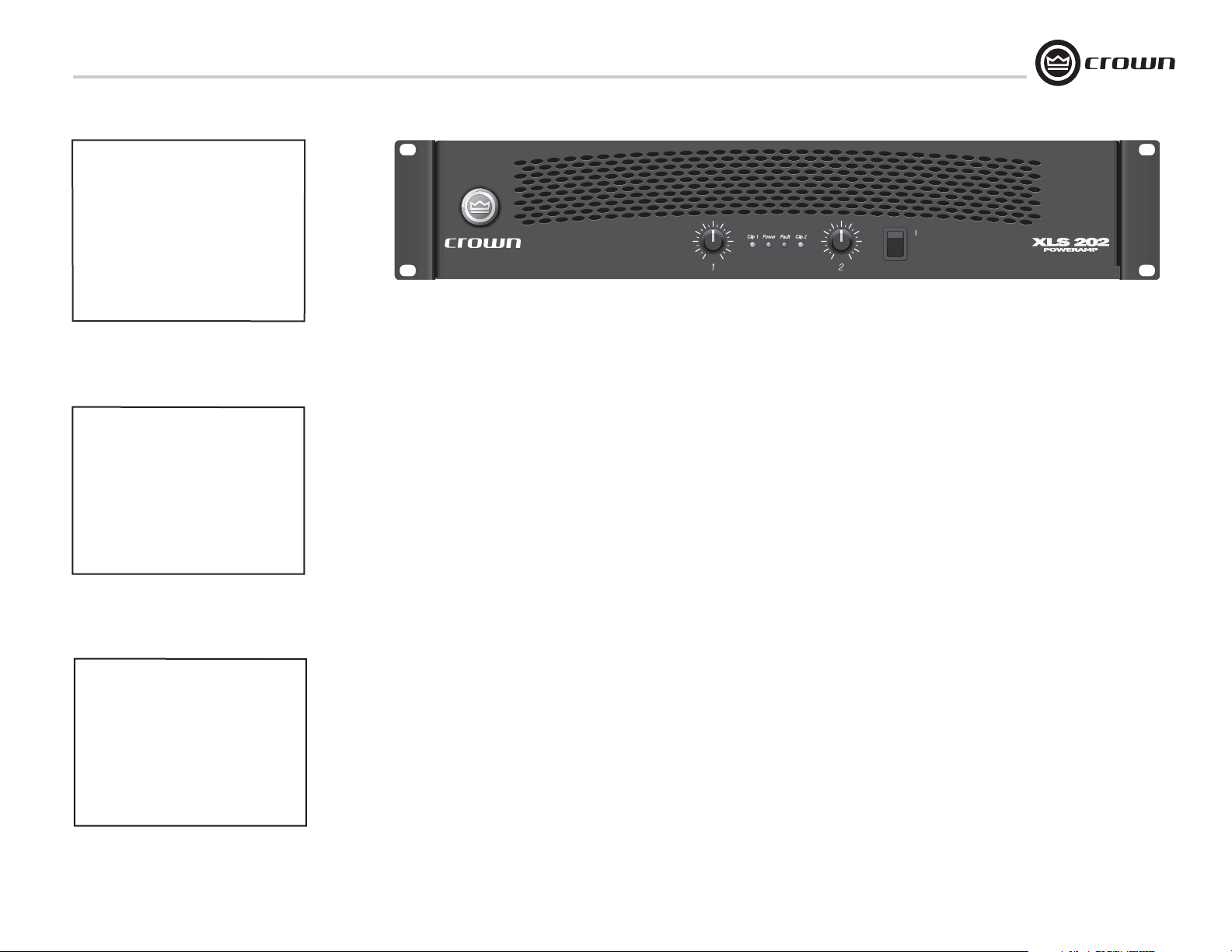
XLS 202
Operation Manual
Obtaining Other Language Versions:
local Crown Distributor. If you need assistance locating your local distributor, please contact Crown at 574-294-8000.
This manual does not include all of the details of design, production, or variations of the equipment. Nor does it cover every possible
situation which may arise during installation, operation or maintenance.
The information provided in this manual was deemed accurate as of the publication date. However, updates to this information may have
occurred. To obtain the latest version of this manual, please visit the Crown website at www.crownaudio.com.
Trademark Notice:
respective owners.
Crown and Amcron are registered trademarks of Crown International. Other trademarks are the property of their
To obtain information in another language about the use of this product, please contact your
Some models may be exported under the name Amcron.
®
XLS 402
XLS 602
©2004 by Crown Audio Inc., P.O. Box 1000, Elkhart, Indiana 46515-1000 U.S.A. Telephone: 574-294-8000
133465-6
1/04
XLS Series Power Amplifiers
1) Read these instructions.
2) Keep these instructions.
3) Heed all warnings.
4) Follow all instructions.
5) Do not use this apparatus near water.
6) Clean only with a dry cloth.
7) Do not block any ventilation openings. Install
in accordance with the manufacturer’s instructions.
8) Do not install near any heat sources such as
radiators, heat registers, stoves, or other
apparatus that produce heat.
9) Do not defeat the safety purpose of the polarized or grounding-type plug. A polarized plug
has two blades with one wider than the other.
A grounding-type plug has two blades and a
third grounding prong. The wide blade or the
third prong is provided for your safety. If the
provided plug does not fit into your outlet,
consult an electrician for replacement of the
obsolete outlet.
10) Protect the power cord from being walked on
or pinched, particularly at plugs, convenience
receptacles, and the point where they exit from
the apparatus.
11) Only use attachments/accessories specified
by the manufacturer.
12) Use only with a cart, stand, bracket, or table
specified by the manufacturer, or sold with the
apparatus. When a cart is used, use caution
when moving the cart/apparatus combination
to avoid injury from tip-over.
13) Unplug this apparatus during lightning storms
or when unused for long periods of time.
14) Refer all servicing to qualified service personnel. Servicing is required when the apparatus
has been damaged in any way, such as powersupply cord or plug is damaged, liquid has
been spilled or objects have fallen into the
apparatus, the apparatus has been exposed to
rain or moisture, does not operate normally,
or has been dropped.
15) To reduce the risk of fire or electric shock, do
not expose this apparatus to rain or moisture.
TO PREVENT ELECTRIC SHOCK DO NOT REMOVE
TOP OR BOTTOM COVERS. NO USER SERVICEABLE PARTS INSIDE. REFER SERVICING TO
QUALIFIED SERVICE PERSONNEL.
À PRÉVENIR LE CHOC ÉLECTRIQUE N’ENLEVEZ
PAS LES COUVERCLES. IL N’Y A PAS DES PARTIES SERVICEABLE À L’INTÉRIEUR. TOUS REPARATIONS DOIT ETRE FAIRE PAR PERSONNEL
QUALIFIÉ SEULMENT.
IMPORTANT
XLS Series amplifiers require Class 2 output wiring.
MAGNETIC FIELD
CAUTION! Do not locate sensitive high-gain equipment such as preamplifiers or tape decks directly
above or below the unit. Because this amplifier has
a high power density, it has a strong magnetic field
which can induce hum into unshielded devices that
are located nearby. The field is strongest just above
and below the unit.
If an equipment rack is used, we recommend locating the amplifier(s) in the bottom of the rack and the
preamplifier or other sensitive equipment at the top.
WATCH FOR THESE SYMBOLS:
The lightning bolt triangle is used to alert the user
to the risk of electric shock.
The exclamation point triangle is used to alert the
user to important operating or maintenance instructions.
FCC COMPLIANCE NOTICE
This device complies with part 15 of the FCC rules. Operation is subject to the following
two conditions: (1) This device may not cause harmful interference, and (2) this device
must accept any interference received, including interference that may cause undesired
operation.
CAUTION: Changes or modifications not expressly approved by the party responsible for
complicance could void the user’s authority to operate the euqipment.
NOTE: This equipment has been tested and found to comply with the limits for a Class B
digital device, pursuant to part 15 of the FCC Rules. These limits are designed to provide
reasonable protection against harmful interference in a residential installation. This equipment generates, uses, and can radiate radio frequency energy and, if not installed and used
in accordance with the instruction manual, may cause harmful interference to radio communications. However, there is no guarantee that interference will not occur in a particular
installation. If this equipment does cause harmful interference to radio or television reception, which can be determined by turning the equipment off and on, the user is encouraged
to try to correct the interference by one or more of the following measures:
• Reorient or relocate the receiving antenna.
• Increase the separation between the equipment and receiver.
• Connect the equipment into an outlet on a circuit different from that to which the receiver
is connected.
• Consult the dealer or an experienced radio/TV technician for help.
page 2
Operation Manual
XLS Series Power Amplifiers
Crown International, Inc.
Issued By: Crown International, Inc.
1718 W. Mishawaka Road
Elkhart, Indiana 46517 U.S.A.
European Representative’s Name and Address:
Nick Owen
19 Clos Nant Coslech
Pontprennau
Cardiff
CF23 8ND United Kingdom
Equipment Type: Commercial Audio Power Amplifiers
Family Name: XLS Amplifiers
Model Names: XLS 202, XLS 402, XLS 602, XLS 402TX, XLS 602TX
EMC Standards:
EN 55103-1:1995 Electromagnetic Compatibility - Product Family Standard for Audio, Video, Audio-Visual and Entertainment Lighting Control Apparatus for Professional Use, Part 1: Emissions
EN 55103-1:1995 Magnetic Field Emissions-Annex A @ 10 cm and 1 M
EN 61000-3-2:1995+A14:2000 Limits for Harmonic Current Emissions (equipment input current 16A per phase)
EN 61000-3-3:1995 Limitation of Voltage Fluctuations and Flicker in Low-Voltage Supply Systems Rated Current 16A
EN 55022:1992 + A1: 1995 & A2:1997 Limits and Methods of Measurement of Radio Disturbance Characteristics of ITE: Radiated, Class B Limits; Conducted, Class B
EN 55103-2:1996 Electromagnetic Compatibility - Product Family Standard for Audio, Video, Audio-Visual and Entertainment Lighting Control Apparatus for Professional Use, Part 2: Immunity
EN 61000-4-2:1995 Electrostatic Discharge Immunity (Environment E2-Criteria B, 4k V Contact, 8k V Air Discharge)
EN 61000-4-3:1996 Radiated, Radio-Frequency, Electromagnetic Immunity (Environment E2, Criteria A)
EN 61000-4-4:1995 Electrical Fast Transient/Burst Immunity (Criteria B)
EN 61000-4-5:1995 Surge Immunity (Criteria B)
EN 61000-4-6:1996 Immunity to Conducted Disturbances Induced by Radio-Frequency Fields (Criteria A)
EN 61000-4-11:1994 Voltage Dips, Short Interruptions and Voltage Variation
Safety Standard:
EN 60065: 1998 Safety Requirements - Audio Video and Similar Electronic Apparatus
DECLARATION of CONFORMITY
Sue Whitfield
574-294-8289
swhitfield@crownintl.com
I certify that the product identified above conforms to the requirements of the EMC Council Directive 89/336/EEC as amended by 92/31/EEC, and the Low Voltage Directive 73/23/EES as amended by 93/68/EEC.
Signed
Operation Manual
Larry Colburn
Title: Senior Vice President of Manufacturing
Due to line current harmonics, we recommend that you contact your supply authority before connection.
Date of Issue: January 1, 2001
page 3

Table of Contents
XLS Series Power Amplifiers
Important Safety Instructions .......................................................2
Declaration of Conformity ............................................................3
1 Welcome ................................................................................5
1.1 Features ...........................................................................5
1.2 How to Use This Manual ..................................................5
2 Setup ......................................................................................6
2.1 Unpack Your Amplifier ....................................................6
2.2 Install Your Amplifier ......................................................6
2.3 Ensure Proper Cooling ...................................................6
2.4 Choose Input Wire and Connectors ................................7
2.5 Choose Output Wire and Connectors ..............................7
2.6 Wire Your System ...........................................................8
2.6.1 Stereo Mode...........................................................8
2.6.2 Bridge-Mono Mode ...............................................9
2.7 Connect to AC Mains ......................................................10
2.8 Protecting Your Speakers ................................................10
2.9 Startup Procedure ...........................................................10
3 Operation .............................................................................11
3.1 Precautions .....................................................................11
3.2 Front Panel Controls and Indicators ...............................12
3.3 Back Panel Controls and Connectors...............................13
4 Advanced Features and Options ......................................14
4.1 Protection Systems ........................................................ 14
4.1.1 Output Current Limiting......................................... 14
4.1.2. DC Protection ......................................................14
4.1.3 Circuit Breaker....................................................... 14
4.1.4 Thermal Protection ...............................................14
5 Troubleshooting ..................................................................15
6 Specifications ..................................................................... 16
7 AC Power Draw and Thermal Dissipation ..................... 18
8 Service ... .............................................................................. 21
8.1 Worldwide Service .......................................................... 21
8.2 US and Canada Service .................................................. 21
8.2.1 Service at a US or Canada Service Center ............ 21
8.2.2 Factory Service ..................................................... 21
8.2.3 Factory Service Shipping Instructions ................... 21
9 Warranty .............................................................................. 22
Crown Factory Service Information Form ...................................25
page 4
Operation Manual
XLS Series Power Amplifiers
*
XLS 202
2-ohm Stereo (per channel)
4-ohm Stereo (per channel)
8-ohm Stereo (per channel)
8-ohm Bridge-Mono
4-ohm Bridge-Mono
*1 kHz Power: refers to maximum average power in watts
at 1 kHz with 0.5% THD.
1 kHz
Power
250W
200W
145W
400W
500W
*
XLS 402
2-ohm Stereo (per channel)
4-ohm Stereo (per channel)
8-ohm Stereo (per channel)
8-ohm Bridge-Mono
4-ohm Bridge-Mono
*1 kHz Power: refers to maximum average power in watts
at 1 kHz with 0.5% THD.
XLS-602
2-ohm Stereo (per channel)
4-ohm Stereo (per channel)
8-ohm Stereo (per channel)
8-ohm Bridge-Mono
4-ohm Bridge-Mono
*1 kHz Power: refers to maximum average power in watts
at 1 kHz with 0.5% THD.
1 kHz
Power
570W
400W
260W
800W
1,140W
*
1 kHz
Power
840W
600W
370W
1,200W
1,680W
1 Welcome
The XLS Series of power amplifiers from Crown
represents a new era in affordable, quality
power amplification. The line consists of three
models in a uniform, rugged chassis, incorporating the best of tried-and-true design principles and innovative features.
Modern power amplifiers are sophisticated
pieces of engineering capable of producing
extremely high power levels. They must be
treated with respect and correctly installed if
they are to provide the many years of reliable
service for which they were designed.
In addition, XLS Series amplifiers include a
number of features which require some explanation before they can be used to their maximum advantage.
Please take the time to study this manual so
that you can obtain the best possible service
from your amplifier.
1.1 Features
•Simple, reliable design incorporates many
popular features.
•Housed in a rugged, all-steel 2U chassis.
•Efficient forced-air fan prevents excessive
thermal buildup.
•Electronically balanced XLR inputs. Touchproof binding post and Speakon
•Features precision detented level controls,
power switch, and four LEDs which indicate
clip for each channel, power and fault conditions.
®
outputs.
1.2 How to Use This Manual
This manual provides you with the necessary
information to safely and correctly setup and
operate your amplifier. It does not cover every
aspect of installation, setup or operation that
might occur under every condition. For additional information, please consult Crown’s
Amplifier Application Guide (available online at
www.crownaudio.com), Crown Technical Support, your system installer or retailer.
We strongly recommend you read all instructions, warnings and cautions contained in this
manual. Also, for your protection, please send
in your warranty registration card today. And
save your bill of sale — it’s your official proof
of purchase.
Operation Manual
page 5
XLS Series Power Amplifiers
2 Setup
2.1 Unpack Your Amplifier
Please unpack and inspect your amplifier for
any damage that may have occurred during
transit. If damage is found, notify the transportation company immediately. Only you can initiate a claim for shipping damage. Crown will
be happy to help as needed. Save the shipping
carton as evidence of damage for the shipper’s
inspection.
We also recommend that you save all packing
materials so you will have them if you ever
need to transport the unit. Never ship the
unit without the factory pack.
YOU WILL NEED (not supplied):
• Input wiring cables
• Output wiring cables
Rack for mounting amplifier (or a stable surface
for stacking)
WARNING: Before you start to set up
your amplifier, make sure you read and
observe the Important Safety Instructions found at the beginning of this
manual.
2.2 Install Your Amplifier
CAUTION: Before you begin, make sure
your amplifier is disconnected from the
power source, with the power switch in
the “off” position and all level controls
turned completely down (counterclockwise).
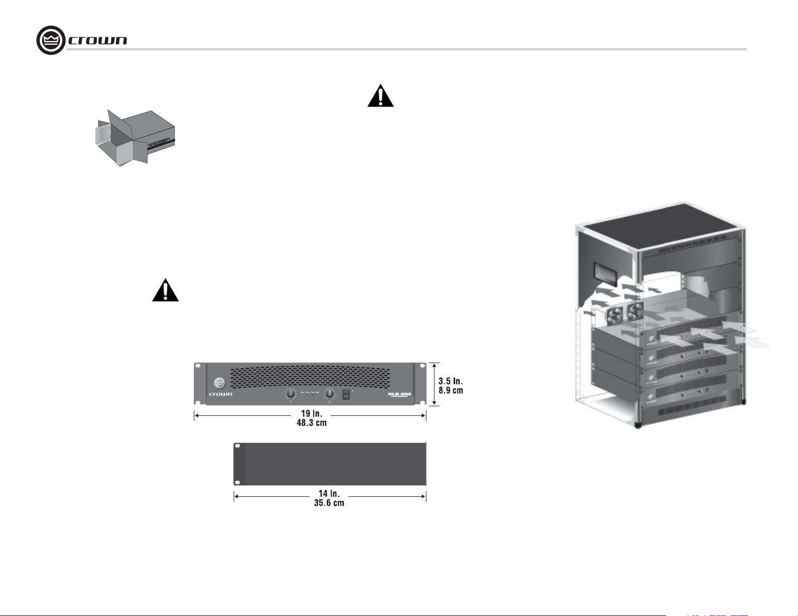
Use a standard 19-inch (48.3 cm) equipment
rack (EIA RS-310B). See Figure 2.1 for amplifier dimensions.
You may also stack amps without using a
cabinet.
NOTE: When transporting, amplifiers should be
supported at both front and back.
2.3 Ensure Proper Cooling
When using an equipment rack, mount units
directly on top of each other. Close any open
spaces in rack with blank panels. DO NOT
block front, rear or side air vents. The side
walls of the rack should be a minimum of two
inches (5.1 cm) away from the amplifier sides,
and the back of the rack should be a minimum
of four inches (10.2 cm) from the amplifier back
panel.
Figure 2.2 illustrates standard amplifier airflow.
page 6
Figure 2.2 Airflow
Figure 2.1
Dimensions
Operation Manual
XLS Series Power Amplifiers
2 Setup
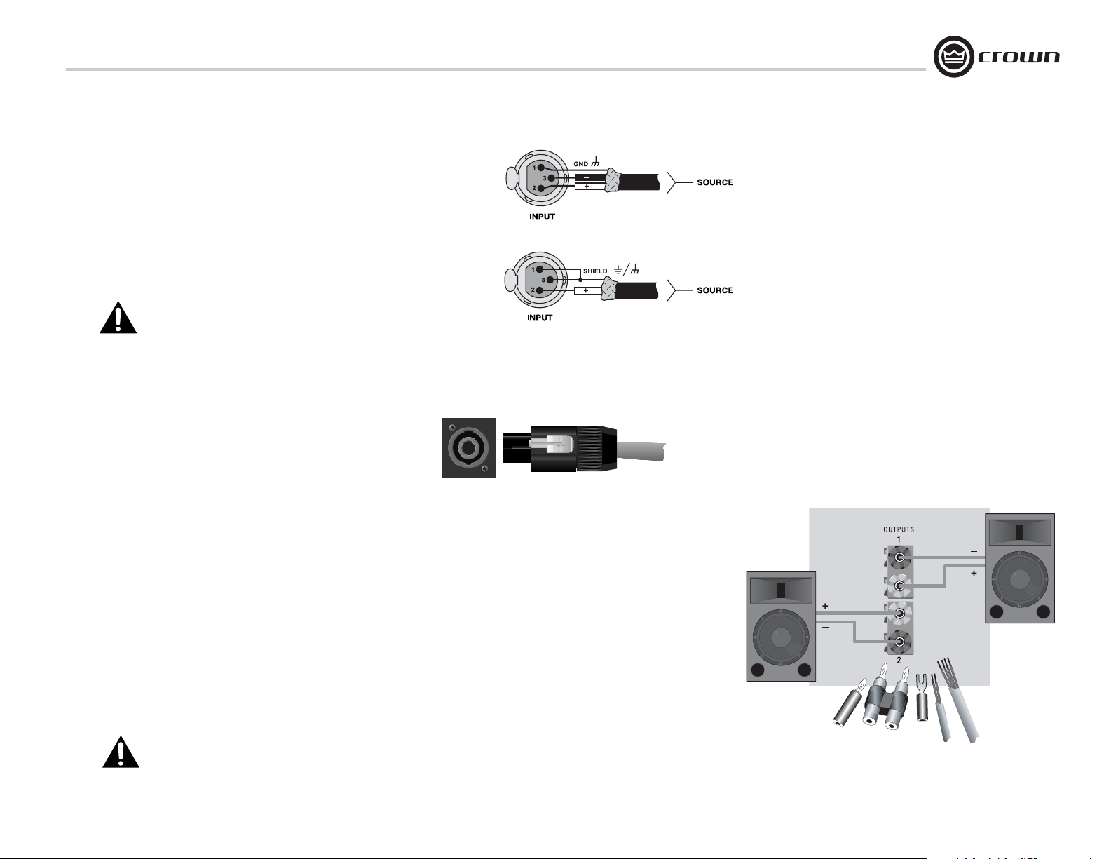
2.4 Choose Input Wire
and Connectors
Crown recommends using pre-built or professionally wired balanced line (two-conductor plus shield), 22-24 gauge cables and
connectors. You should use 3-pin male XLR cable ends at the
amplifier inputs. Unbalanced line may also be used but may
result in noise over long cable runs.
Figure 2.3 shows connector pin assignments for balanced wiring,
and Figure 2.4 shows connector pin assignments for unbalanced
wiring.
NOTE: Custom wiring should only be performed by
qualified personnel.
2.5 Choose Output Wire and Connectors
Crown recommends using pre-built or professionally wired, highquality, two-conductor, heavy gauge speaker wire and connectors.
You may use 2-pole or 4-pole Speakon
or banana plugs, spade lugs, or bare wire for your output connectors (Figure 2.6). To prevent the possibility of short-circuits, wrap
or otherwise insulate exposed loudspeaker cable connectors.
Note: Binding post outputs on European models come
with safety plugs installed to prevent European powercord plugs from being inserted. The top & bottom entry
positions for these connectors should therefore be used
with European models.
Using the guidelines below, select the appropriate size of wire
based on the distance from amplifier to speaker.
Distance Wire Size
up to 25 ft. 16 AWG
26-40 ft. 14 AWG
41-60 ft. 12 AWG
61-100 ft. 10 AWG
101-150 ft. 8 AWG
151-250 ft. 6 AWG
®
connectors (Figure 2.5 )
Figure 2.5
Left: One of Two Speakon
on Back Panel
Right: Speakon
®
Cable Connector
®
Output Connectors
Figure 2.3
Balanced Input
Connector Wiring
Figure 2.4
Unbalanced Input
Connector Wiring
CAUTION: Never use shielded cable for output wiring.
Operation Manual
5-Way Binding Post Connections
Figure 2.6
page 7
2 Setup
2.6 Wire Your System
XLS Series Power Amplifiers
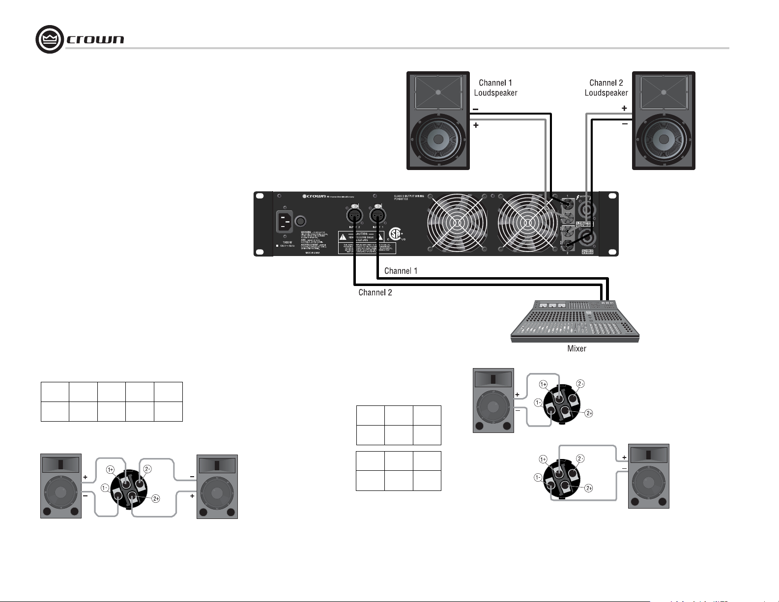
2.6.1 Stereo Mode
Typical input and output wiring is shown in
Figure 2.7
INPUTS: Connect input wiring for both channels.
OUTPUTS: Maintain proper polarity (+/–) on output connectors.
Connect Channel 1 loudspeaker’s positive (+) lead to Channel 1
positive (red) terminal of amp; repeat for negative (–). Repeat
Channel 2 wiring as for Channel 1.
Figure 2.7 shows how to wire stereo speakers to the 5-way binding
posts.
®
To wire stereo speakers to the Speakon
these methods:
Method 1 (Table 1 and Figure 2.8): Wire one Speakon cable connector to two speakers. Insert the Speakon cable connector into the
amplifier’s top Speakon connector.
Method 2 (Table 2 and Figure 2.9): Plug the Channel 1 speaker
into the Channel 1 (top) Speakon connector, and plug the Channel
2 speaker into the Channel 2 (bottom) Speakon connector.
connectors, use one of
Table 1
Stereo Wiring Method 1: Use Top Speakon Only
PIN 1+ 1– 2+ 2–
CH 1+ 1– 2+ 2–
Figure 2.7
System Wiring,
Stereo Mode
Using the 5-way
Binding Posts
Table 2
Stereo Wiring Method 2: Use Both Speakons
Top Speakon
(Channel 1)
PIN 1+ 1–
Figure 2.8 Stereo Wiring Method 1:
Wire Two Speakers to the Top Speakon
Connector
page 8
CH 1+ 1–
PIN 1+ 1–
CH 2+ 2–
Channel 1
Loudspeaker
Bottom
Speakon
(Channel 2)
Channel 2
Loudspeaker
Figure 2.9 Stereo Wiring Method 2:
Connect Each Speaker to a Different Speakon Connector
Operation Manual
XLS Series Power Amplifiers
2 Setup
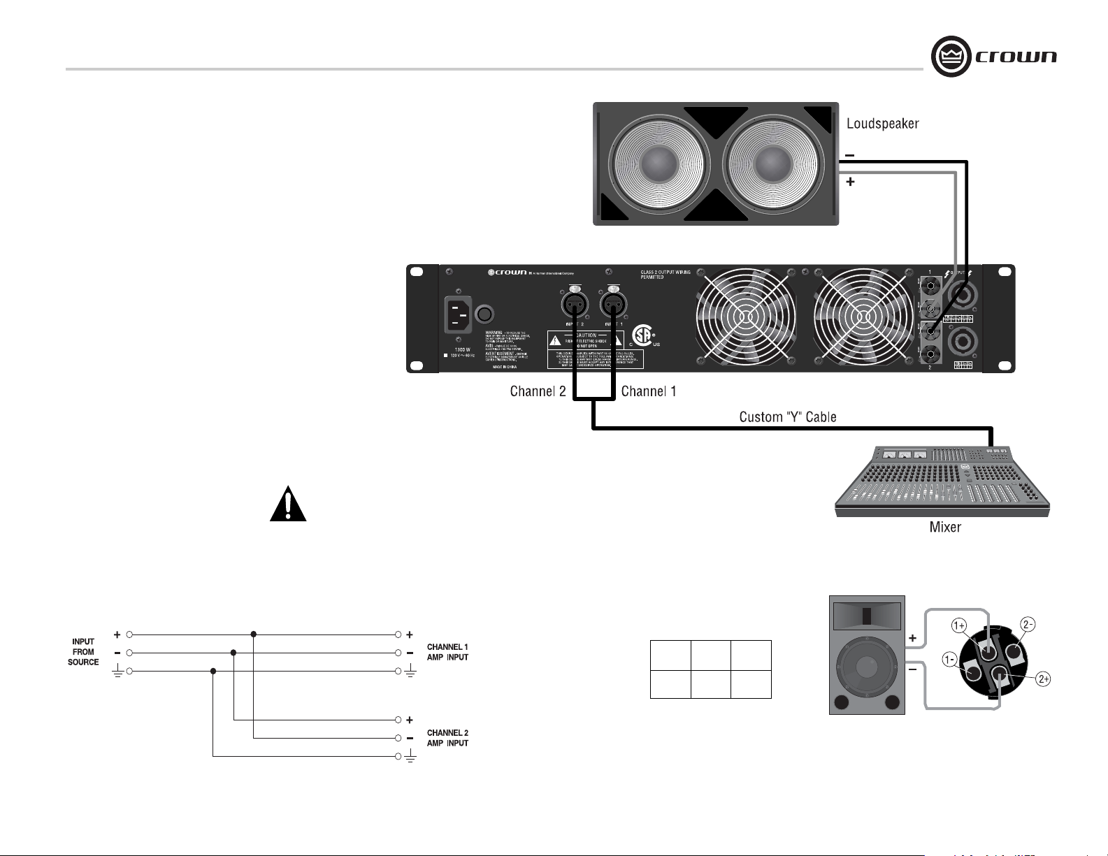
2.6.2 Bridge-Mono Mode
INPUTS: Use a custom “Y” adapter cable, wired
to split the signal and invert the polarity for the
Channel 2 amplifier input as shown in Figure
2.10. We recommend you label the ends of the Y
adapter to help make sure to connect the correct
end to each amplifier input.
Connect the Y adapter between the signal source
and each amplifier input (Figure 2.11).
NOTE: Crown provides a reference of wiring pin
assignments for commonly used connector
types in the Crown Amplifier Application Guide
available at www.crownaudio.
OUTPUTS: There are two ways to wire the amplifier output connectors for Bridge-Mono mode:
1) Wire the speaker across the red binding post
of each channel (Figure 2.11). Do not use the
black binding posts when the amp is being operated in Bridge-Mono mode.
2) Wire the speaker only to the top Speakon connector as shown in Table 3 and Figure 2.12.
NOTE: The Channel 1 and 2 level controls
MUST be set to identical settings when
operating the XLS amplifier in BridgeMono mode.
Figure 2.11 Bridge-Mono Wiring of 5-Way Binding Posts
Operation Manual
Figure 2.10
Custom Y-Input
Cable
Table 3
Top Speakon Wiring for Bridge-Mono
PIN 1+ 2+
CH 1+ 1–
Figure 2.12 Alternate Bridge-Mono Wiring:
Loudspeaker Wired to Amplifier’s Top
Speakon
Connector
page 9
 Loading...