

Page 1
C
Specifications
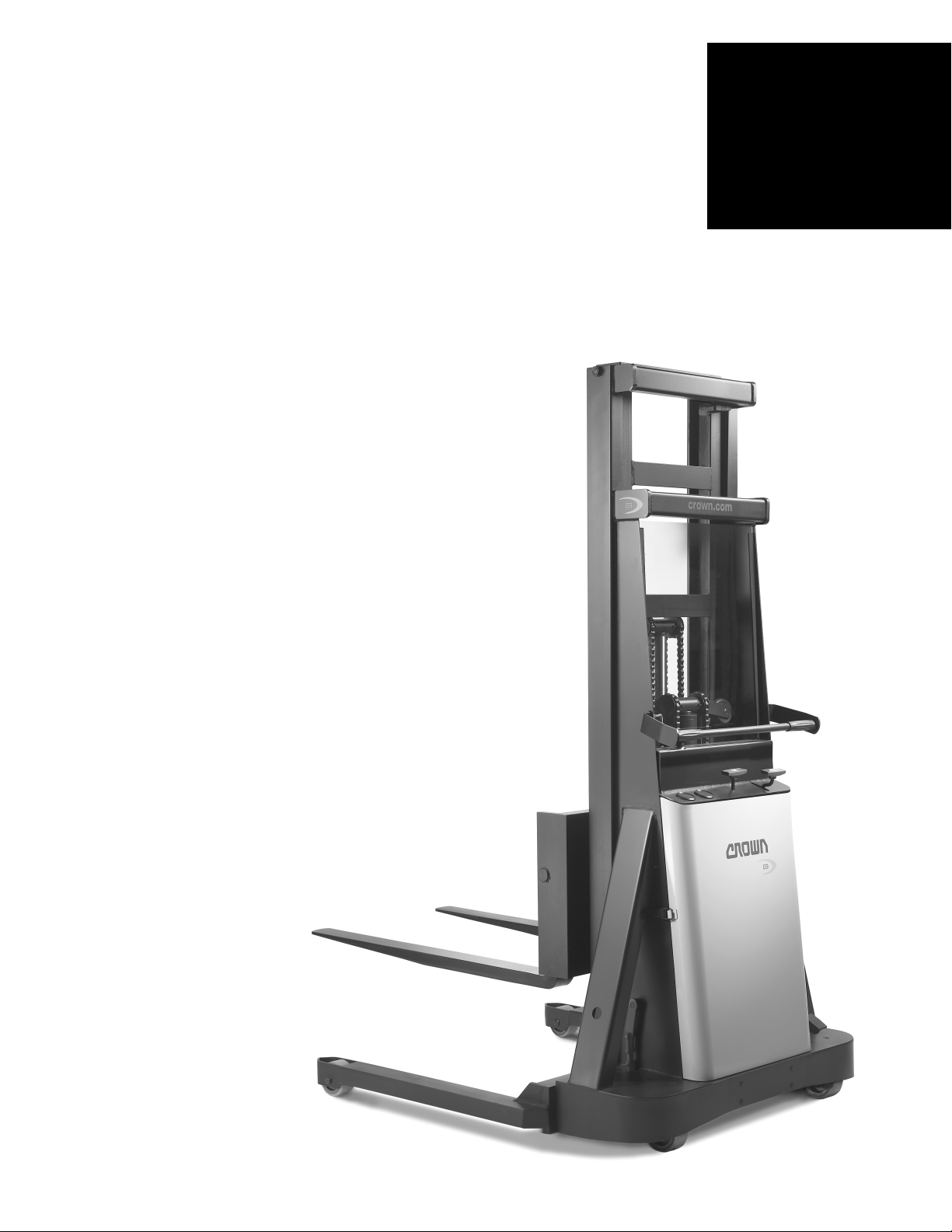
B Series
Power Lift
Stackers
B
Series
Page 2
13
26"
4.75"
16.38"
25.88"
13
6"
25"
3"
32.5"
ø 4" x 2"
ø 5" x 1.88"
4.06"
2.00"
4.5"
2.75"
36"
7
9
14
10
8
11
36"
4"
2.00"
1.5"
ø 4" x 2"
ø 5" x 1.88"
1.5"
10 14
9
7
11
8
C
B Series
Specifications
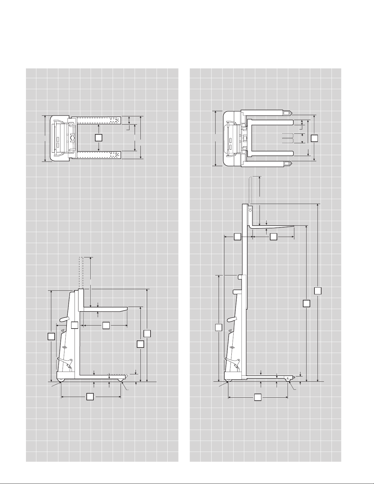
Model 20B
Fork Over
Model 20BS & BT
Straddle
Page 3

B Series
Specifications
1 Manufacturer Crown Equipment Corporation
2 Model 20B 20BS 20BT
Mast Type Single Single Telescopic
Load Handling Configuration
Fork Over Straddle Straddle
3 Power Electric** 12-Volt Lift System
4 Operator Type Walkie
5 Load Capacity* Max lb 2000
6 Load Center in 24
7 Lifting Height in 57 67 54 64 90 110
Free Lift in 52.5 62.5 52.5 62.5 51 61
8 Collapsed Height in 78.3 78.3 78.3 78.3 81.5 81.5
9 Extended Height in 78.3 79 78.3 78.3 111 131
10 Head Length in 17 19.12 21.5
11 Wheelbase in 36.3 41.81 43.5
12 Net Weight with Batteries lb 755 855 1295
13 Inside Straddle in 18.12 26.5 32-50
Outside Straddle in 6.3" + Inside Straddle Dimension
14 Fork Length in 30 Standard, 36, 42 and 48 Available
15 Lifting Speeds
w/wo Load fpm
18/35
16 Lowering Speeds
w/wo Load fpm
38/22
General Information
Dimensions
* Attachments and longer load dimensions may result in derating of the capacity. Contact local dealer.
** Manually propelled for horizontal travel
B Series
Technical Information
Capacity
2000 lb at 24" load center.
Batteries
Two 6-volt, three cell 17 plate
lead acid batteries. Each battery
rated
at 100 amp hours at 20
hour rate
, and 87 amp hours at
six hour rate.
Charger
Built-in 110/130 volt silicon rectifier
type. Built-in ammeter shows
charging rate during charging
cycle. Other voltages available.
Standard Equipment
1. 12-volt fused electrical
system
2. Plexiglass safety shield
3. Dual floor locks
4. Emergency power disconnect
5. Batteries
6. Built-in 120-volt battery
charger
7. Adjustable outriggers (BT only)
Optional Equipment
1. Snap-on platform
2. Polyurethane load and
caster wheels
3. Load backrest
4. Key switch
5. Remote lift/lower control with
12' coil cord and push-button
station
6. Fifth-wheel steering
Chassis
Fabricated from steel plate
and bar stock completely shotblasted prior to finish coat. Base
plate formed from steel plate
and reinforced with protective
bumper skirt. Vertical guide mast
assembly welded as an integral
part of main chassis. Guide mast
channels on telescopic models
are a special, hot-rolled steel
section designed exclusively for
lift truck use.
Carriage Rollers
Alloy steel rollers contoured to
fit mast and equipped with
roller bearings.
Lift Chain
Two alloy steel leaf-type lift chains.
Outriggers
Formed from heavy-gauge steel
plate with end contoured around
load wheel. Outrigger and load
wheel axles are flush to prevent
pallet or skid damage.
Forks
1.5" thick x 3" wide forged-steel
forks with full upset heel standard
on all BS and BT models. Fixed,
formed 2.75" thick x 4.75"
wide steel forks welded to fork
carriage on B models.
Wheels and Tires
Standard equipment includes:
Steel caster wheels
5" dia x 1.88" face.
Steel load wheels 4" x 2" face.
All wheels equipped with roller
bearings.
Operator Controls
1. Raise/lower lever located
between chassis uprights.
Provides a fixed lifting speed
and variable speed lowering.
2. Safety power disconnect lever,
located next to raise/lower
control, shuts off all battery
power to truck.
3. Foot operated floor lock lever.
Pedal raises/lowers two
spring-loaded, flat-rubber
pads.
Hydraulic System
1. Heavy-duty motor, gear pump,
check valve, relief valve and
control valve
2. Pressure compensated flow
control valve to regulate
lowering speed.
3. Lift cylinders equipped with
polyurethane packings.
4. Drain line from lift cylinder
to reservoir.
5. Hydraulic fluid reservoir
equipped with breather-filter
to prevent foreign matter from
entering hydraulic system.
6. Overload valve set to bypass
fluid to reservoir when system
reaches maximum pressure.
Safet y Shield
Clear, high-impact plexiglass to
help protect operator from chains
and cylinder.
Other Options
1. Audible travel alarm
2. Flashing lights
Safety considerations and
dangers associated with audible
travel alarms and flashing lights
include:
• Multiple alarms and/or lights
can cause confusion.
• Workers ignore the alarms
and/or lights after day-in and
day-out exposure.
• Operator may transfer the
responsibility for “looking out”
to the pedestrians.
• Annoys operators and
pedestrians.
Dimensions and performance
data given may vary due to
manufacturing tolerances.
Performance is based on an
average size vehicle and is
affected by weight, condition of
truck, how it is equipped and the
conditions of the operating area.
Crown products and specifications are subject to change
without notice.
Page 4

C
Crown Equipment Corporation
New Bremen, Ohio 45869 USA
Te l 419-629-2311
Fax 419-629-3796
crown.com
Because Crown is continually improving its products,
specifications are subject to change without notice.
Crown and the Momentum symbol are trademarks of
Crown Equipment Corporation.
Copyright 2002-2004 Crown Equipment Corporation
SF14108 Rev. 5/04
Printed in U.S.A.
 Loading...