

Page 1
1 2 3
MRX-220N
OUTDOOR DOUBLE DUAL
MIRROR OPTICS
PASSIVE INFRARED &
MICROWAVE DETECTOR
ELECTRONIC ENGINEERING LTD.
INSTALLATION INSTRUCTIONS
P/N: 7101296 REV.A A.Y.
MRX–220N DESCRIPTION
The MRX-220N is a combination of DOUBLE
DUAL PIR with MIRROR optics & MW detectors,
specially designed for outdoor and harsh
environment applications.
The Mirror DOUBLE DUAL detector MRX-220N
uses varifocal mirror that improves the focus and
the level of energy received by the Pyro Sensor.
This combination assures “false alarm free”
operation.
The 16 position rotate switch changes the MW
and PIR sensitivity so that the effective pattern
will be scaled.
MRX–220N FEATURES
• DOUBLE DUAL PYRO sensor and full pattern
mirrors for outstanding detection performance
and elimination of false alarms.
• MW detection based on Doppler concept.
• FET based DRO with stripline antenna.
• VLSI based electronics with movement speed
spectrum analysis.
• N.O. & N. C. Relays switched at the same time.
• Height installation calibrations free from 1.5m to
3.0m (5ft to 10ft).
• Pet Immunity up to 10, 20, 30 or 40kg –
Selectable
• MW and PIR sensitivity adjustment.
• Environmental immunity.
• Temperature compensation.
MOUNTIN G THE DETECTOR
Choose a location most likely to intercept an
intruder. See detection pattern in FIG.: 7. The
DOUBLE DUAL high quality sensor detects
motion crossing the beam; it is less sensitive
detecting motion towards the detector.
The MRX-220N performs best when provided with
a constant and stable environment.
The bracket provides MRX-220N installation on
the wall and on the pole, allows changing the
installation angle (vertically and horizontally) in
wide range (FIG.2).
AVOID THE FOLLOWING LOCATIONS
∗ Facing direct sunlight.
∗ Facing areas subject to rapid temperature
changes.
∗ Areas with air ducts or substantial air flows.
∗ Facing metal doors.
NOTE
:
Recommended installation height is 2.4m.
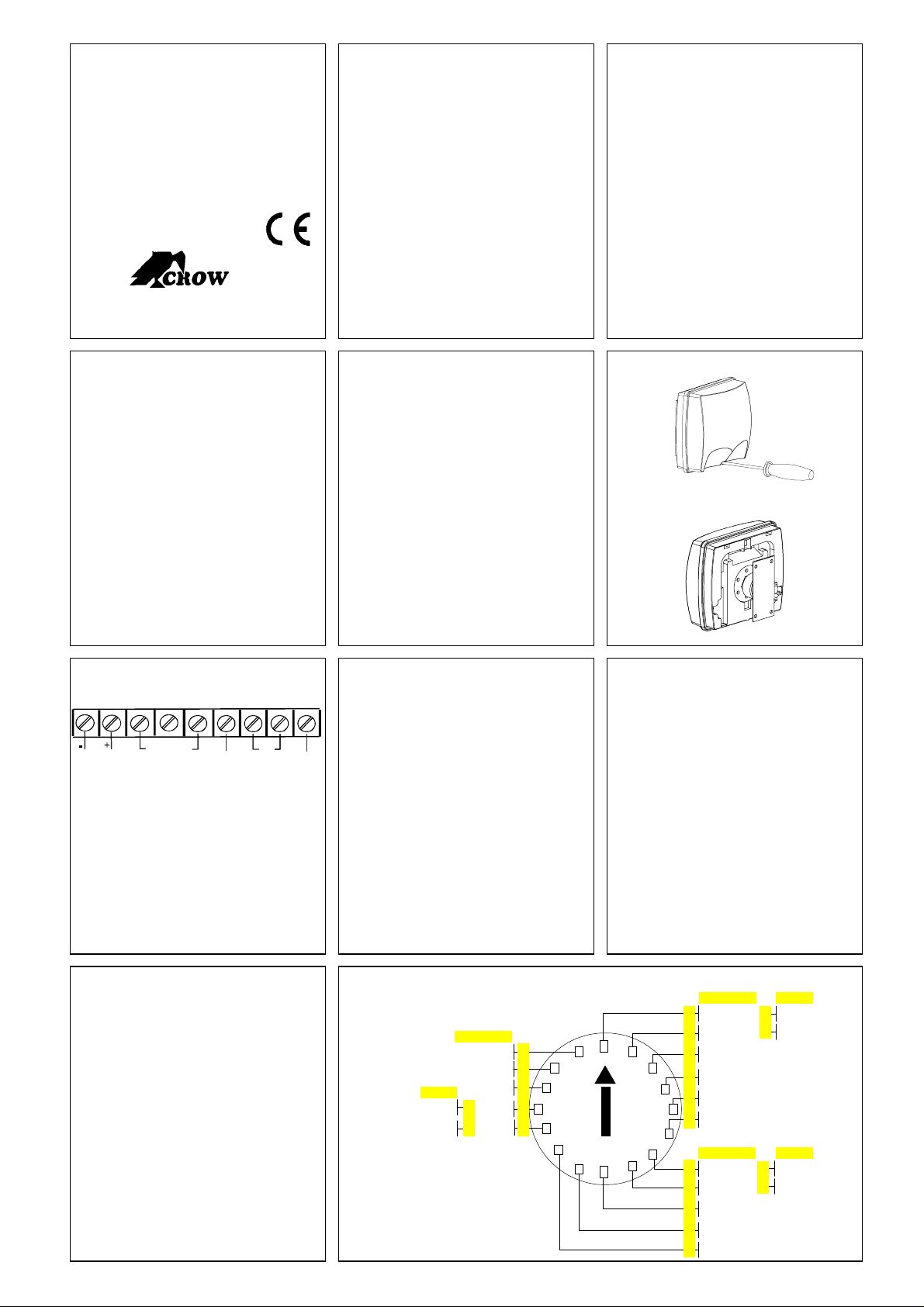
FIG. 3 -
TERMINAL BLOCK CO NNE CTIONS
1 2 3 4 5 6 7 8 9
12V NC C NO EOL TAMPER EOL
RELAY
Terminal 1 - Marked “ - ” (GND)
Connect to the ground of the control panel.
Terminal 2 - Marked “ + ” (+12V)
Connect to a positive Voltage of 8.2 -16Vdc
source (usually from the alarm control unit)
Terminals 3,4 & 5 - Marked “ NC C NO ”
These are the output relay contacts of the
detector. Connect to a normally closed or
normally opened zone in the control unit.
Terminals 7 & 8 - Marked “ TAMPER ”
If a Tamper function is required connect these
Terminals to a 24-hour normally closed protective
zone in the control unit.
INSTALLING TH E DETECTOR
1. To remove the front cover, unscrew the
holding screw. Insert a screwdriver between
the front and the bottom and pull gently, until
the front cover is disengaged. (FIG 1)
2. Break out the desired holes for proper wiring
as per FIG 6.
3. Insert the wire through the wire access hole,
and mount the detector base to the wall with
the necessary number of screws.
4. Access for wiring connections is very easy
with the terminal block located on the PCB.
See FIG 3.
5. Replace the cover by inserting it back in the
appropriate closing, screw the holding screw.
If the front cover of the detector is opened, an
immediate alarm signal will be sent to the control
unit.
Terminals 6 & 9 - Marked “ EOL ”
End of line - options.
When an intruder is detected, alarm relays (N.O.
and N.C.) will switch for 1.8 sec.
WIRE SIZE REQUIREMENTS
Use #22 AWG or larger wires. Use the following
table to determine required wire gauge and length.
Wire Gauge: # 22 20 18 16
Wire Length: m 205 310 510 870
Ft. 800 1200 2000 3400
LED INDICATORS
YELLOW LED - MW detection, is blinking during
warm up period and self testing
GREEN LED - PIR detection
RED LED – Alarm
FIG. 1 - REMOVAL OF FRONT COVER
FIG. 2 – BRACKET ASSEMBLY
SENSITIVITY AND RANGE ADJUSTMENT
The calibration of range and sensitivity is
performed by single digital 16 positional rotary
switch.
There are 3 groups of switch setting according to
detection range.
Each group is devided to levels of sensitivity
according to installation environment.
The value of sensitivity level is changed according
to optic
For WA (Wide Angle ) mirror optic
Group A - positions 0 – 5 – set sensitivity for 21m
detection range
Group B - positions 6 – A – set sensitivity for15m
detection range
Group C - positions B – F – set sensitivity for 7m
detection range
For LR (Long Range ) mirror optic
Group A - positions 0 and 1 – set sensitivity for 40m
detection range
Group B - positions 6 and 7 – set sensitivity for28m
detection range
Group C - positions B and C – set sensitivity for
15m detection range
The 5 or 6 levels in each group are used to set up
the sensitivity according to environment.
Each range group includes 5 or 6 setting levels
according to environmental condition risk.
For example:
If detector is used for 15m range in open space with
sunlight – set switch to position 8 or 9.
FIG.4 - R OTARY SWITCH S ETTING
WA
Noise Area
Very High Risk
LR
High Risk
Low Risk
Installation Hight: 3m
Bracket Angle: 0°
15m
High Risk
Risk
Low Risk
7m
D
B
40m
Low Risk
28m
High Risk
LRWA
Low Risk
High Risk
LR
Low Risk
3
4C
5
Risk
High Risk
21m
Very High Risk
Noise Area
Extreme Noise Area
WA
Low Risk
Risk
High Risk
15m
Very High Risk
Noise Area
0
1F
E
A
9
8
2
6
7
Page 2
13 14 15
pp
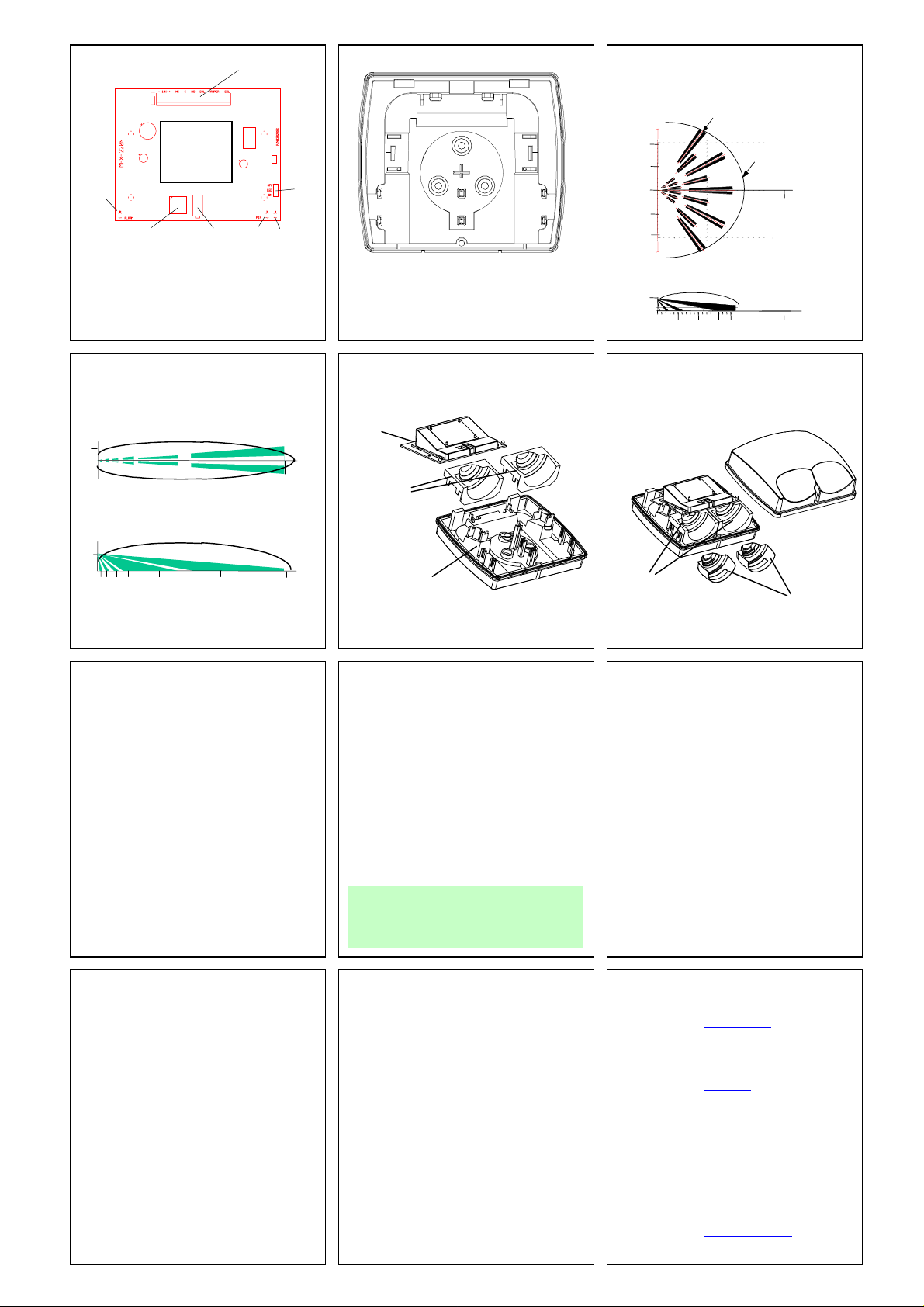
FIG.5 - PCB LAYOUT
ANTENNA
DOPPLER
ALARM
LED
ROTARY
SWITCH
Double Dual Pyrosensors on opposite side
Tamper
BLOCK
CONNECTOR
PIR MW
LED LED
FIG. 6 - OPTIONAL HOLES
A
A
B
LED
Mode
Jumper
B
B
A. Wire access holes
B. Use for fl at wall mounting or for
mounting with the help of bracket
FIG. 7 - WA PIR + MW DETECTION
PATTERN
10m
5m
0m
5m
10m
2.4m
TOP VIEW
WA mirror 105 ° (PIR)
MW pattern
21m
`
SIDE VIEW
30m
30m 21m 10m 5m
FIG. 8 - LONG RANGE CURTAIN
PATTERN
1.5
1.5
2.4
m
m
0
m
m
m
0
m
1.5
TOP VIEW
m
m 5 m 3
10
m
40
m
25
m
40
SIDE VIEW
REPLACING MIRRORS (FIG.9)
1. Remove the front cover.
2. Pull out the PCB.
3. Pull out the old mirrors from slots.
4. Replace a new mirrors – insert mirror pins into
the slots; don’t touch the mirror from internal
side.
5. Replace the PCB.
6. Replace the front cover.
ASSEMBLY AND RE PLACING OF PET
IMMUNITY MASKS (SEE FIG.10)
1. Remove the front cover.
2. Put pet masks on the mirrors or replace them.
3. Replace the front cover.
FIG. 9 – REPLACING MIRRORS
PCB with
antenna
Do
ler
Mirrors
Plastic base
TEST PROCEDURES
Wait one-minute for warm-up time after applying
power.
Make the test at the protected area free of moving
people
LED should be in enable position.
.
Walk test
1. Start walking slowly across the detection zone.
2. Observe that the red LED lights whenever
motion is detected.
3. Allow 5 sec. between each test for the detector
to stabilize.
NOTE:
Walk tests should be done at least once a year to
confirm proper operation of the detector.
You must reset the detector from
Control Panel before the new
settings will take effect
FIG. 10 –ASSEMBLY OF PET
IMMUNITY MASKS
Mirrors
Pet masks
TECHNICAL SPECIFICATIONS
Detection Method DOUBLE DUAL element PIR & MW
Detection Speed 0.3 - 1.5 m/sec (1 - 5 ft/sec)
Maximum ripple 2.4Vdc peak to peak at 12Vdc
Power Input 8.2 to 16 Vdc
Current Draw Active : 27mA + 3mA
Standby: 17mA + 3mA
Bi Directional
Temperature YES
Alarm Period 1.8 sec
Alarm Output N.C 28Vdc 0.1 A with 10 Ohm
series protection resistors
N.O 28Vdc 0.1 A with 10 Ohm
series protection resistors
Tamper Switch N.C 28Vdc 0.1A with 10 Ohm series
Protection resistor - open when
cover is removed
Warm Up Period 30 sec
TECHNICAL SPECIFICATIONS (CONT.)
Operating Temperature -20°C to +50°C(-4°F to +122°F)
RFI Protection 30V/m 10 - 1000MHz
EMI Protection 50,000V of electrical
interference from lightning or
power through
Visible Light Protection stable against halogen light
2.4 m (8ft ) or reflected light
MW output power min + 13 dBm IERP
MW center frequency 10.525 GHz +/-3MHz
MW harmonic emission -7.3 dBm
Dimensions 154mm x 114mm x 74mm
(6.1” x 4.5” x 2.9”)
Weight 290gr. (10.23oz)
.
MRX220N
CROW reserves the rights to change
specifications without prior notice
CROW LIMITED WARRANTY
(Crow) warrants this product to be free from defects in mat erials and workmanship
under normal use and service f or a peri od of one year from t he last day of t he week
and year whose numbers are printed on the printed circuit board inside this product.
Crow’s obligation is lim ited to repairing or replaci ng this product, at its opti on, free of
charge for materials or labor, if it is proved to be defective in materials or
workmanship under normal use and service. Crow shall have no obl igat ion under thi s
Limited Warranty or otherwise i f the product is altered or improperly repaired or
serviced by anyone other then Crow.
There are no warranties, expressed or implied, of merchantability or fitness for a
particular purpose or otherwise, which extend beyond the description on the face
hereof. In no case shal l Crow be l iable to anyone f or any consequential or incident al
damages for breach of t his or any other warranty, expressed or implied, or upon any
other basis of liability whatsoever, even if the loss or damage is caused by Crow’s
own negligence or fault.
Crow does not represent that this product can not be compromised or circumvented;
that this product w i ll prevent any person injury or property loss or damage by burglary,
robbery, fire or otherwise; or that this product wil l in all cases provide adequate
warning or protection. Purchaser understands that a properly installed and maintained
product can only reduce the risk of burglary, robbery or other events occurring without
providing an alarm, but it is not insurance or a guarantee that such will not occur or
that there will be no personal injury or property loss or damage as a result.
Consequently, Crow shall have no liabili ty for any personal injury; property damage or
any other loss based on claim that this product fail ed to give any warning. However, if
Crow is held liable, whether directly or i ndirectly, for any loss or damage arising under
this limited warranty or otherwise, regardless of cause or origin, Crow’s maximum
liability shall not in any case exceed the purchase price of this product, which shall be
the complete and exclusive remedy against Crow.
CROW ELECTRONIC ENGINEERING LTD.
ISRAEL: 57 Hamelacha St., Holon 58855
Tel: 972-3-5569937 /8 /9
Fax: 972-3-5592981
E-mail: support@crow.co.il
USA: 2160 North Central Road,
Fort Lee, N.J. 07024
Tel: 1-800-GET CROW
or (201) 944 0005
Fax: (201) 944 1199
E-mail:
AUSTRALIA: 429 Nepean HWY Brighton East Vic 3187
Tel: 61-3-9596 7222
Fax: 61-3-9596 0888
E-mail:crow@crowaust.com.au
UK: Unit 5, Bradford on Avon Marina
Widbrook Bradford on Avon
Wiltshire BA15 1UD
Tel: 01225 863 138
Fax: 01225 863 171
POLAND: VIDICON 01-199 Warsaw
Ul. Leszno 34/36
Tel: 48 22 632 9666
Fax: 48 22 632 5543
crow@nis.net
E-mail: vidicon@medianet.com.pl
 Loading...