

Page 1

ELECTRONIC ENGINEERING LTD
ELECTRONIC ENGINEERING LTD
ELECTRONIC ENGINEERING LTDELECTRONIC ENGINEERING LTD
Merlin Pro
Merlin Pro (Ver
Merlin ProMerlin Pro
.
(Ver----2.0)
(Ver(Ver
2.0)
2.0)2.0)
PROGRAMMABLE STAND ALONE WIRELESS RECEIVER
Installation
and
Programming Guide
Safety Technology International (Europe) Ltd
1
Page 2

IMPORTANT NOTICE
All information and data contained in this document is proprietary and confidential.
CROW Electronic Engineering Ltd. shall not be liable, in any event, for any claims for damages or any other
remedy in any jurisdiction whatsoever, whether in an action in contract, tort (including negligence and strict
liability) or any other theory of liability, whether in law or equity including, without limitation, claims for
damages or any other remedy in whatever jurisdiction, and shall not assume responsibility for patent
infringements or other rights to third parties, arising out of or in connection with this document.
Further, CROW Electronic Engineering Ltd. reserves the right to revise this publication and to make changes
to its content, at any time, without obligation to notify any person or entity of such revision changes. These
materials are copyrighted and any unauthorized use of these materials may violate copyright, trademark,
and other laws. Therefore, no part of this publication may be reproduced, photocopied, stored on a retrieval
system, or transmitted without the express written consent of CROW Electronic Engineering Ltd. Any new
issue of this document invalidates previous issues.
©CROW Electronic Engineering Ltd. 2005. All rights reserved.
Information in this document is subject to change without notice. No part of this document may be
reproduced or transmitted in any form or by any means, electronic or mechanical, without express written
permission of CROW Electronic Engineering Ltd..
Document Version 0.02.004 P/N 7102452 Rev. C Y.A. / A.Y
March 2006
Page 3

CONTENTS
CONTENTS
CONTENTSCONTENTS
INTRODUCTION .........................................................................................................................4
FEATURES ...............................................................................................................................4
FREEWAVE FULLY SUPERVISED WIRELESS ACCESSORIES .........................................................................5
USER MODE ............................................................................................................................5
USING THE DISPLAY AND KEYPAD ...................................................................................................5
Navigating the Screens ...........................................................................................................5
MEMORY (EVENT LOG)................................................................................................................6
Displaying the Event Log .........................................................................................................6
Setting the Date and Time ......................................................................................................6
INSTALLING THE MERLI
INSTALLING THE MERLIN PRO
INSTALLING THE MERLIINSTALLING THE MERLI
INSTALLATION DIAGRAMS.............................................................................................................8
PROGRAMME SEQUENCE LIST.......................................................................................................10
LCD Display Symbol Table...................................................................................................... 10
Entering Numbers .................................................................................................................10
SETTING THE CLOCK..................................................................................................................11
N PRO ................................................................................................... 7
N PRON PRO
INSTALLER MODE ....................................................................................................................12
Accessing the Installer Mode .................................................................................................12
Adding a Wireless Device (Add Zone) ....................................................................................13
Adding a Remote Control key................................................................................................14
Clear Zone ............................................................................................................................16
Clear Remote........................................................................................................................ 17
Changing the Password......................................................................................................... 18
Checking the RSSI (Radio signal strength) .............................................................................. 18
Clear History ......................................................................................................................... 19
Arm To Output ...................................................................................................................... 19
Buzzer Tie.............................................................................................................................20
Remotes Log......................................................................................................................... 21
Version .................................................................................................................................21
Setting the Unit Defaults ....................................................................................................... 22
FUNCTIONS ...........................................................................................................................23
TECHNICAL
TECHNICAL SPECIFICATIONS
TECHNICAL TECHNICAL
SPECIFICATIONS .................................................................................................... 25
SPECIFICATIONSSPECIFICATIONS
CROW ELECTRONIC ENGINEERING LTD. (CROW) WARRANTY POLICY CERTIFICATE .................................26
3
Page 4

Introduction
The Merlin Pro is a programmable standalone wireless receiver with a small LCD display
for easy programming and status indication.
The unit can accept up to 64 wireless detectors and 256 remote controls, eight wireless
units for each one of the outputs.
As soon as a wireless unit is learned into the system, any detection signal from the unit
automatically triggers an output on the Merlin. This output depends on which group and
zone the device is assigned to.
The Merlin Pro has eight outputs (dry contact) that can be connected to Zone inputs on
any wired Control Panel unit, or other suitable device.
The Merlin Pro is protected with a tamper switch that indicates when its service cover is
opened. Merlin Pro will also indicate if a tamper switch is activated on one of the
detectors.
Features
Full 2 x 16 Character LCD display
Keypad with 4 touch pads for programming.
Scrolling menu
Simple to configure
Can learn up to 64 wireless detectors (8 detectors to each output).
Can learn up to 256 remotes control devices each with 4 separate modes:
Password protected access to installer mode
Real Time Clock with back up battery
Tamper protected
Fully supervised – beeps every minute when detector supervision signal is
Beeps every minute when receiving a Low battery signal from one of the
64 event log (FIFO)
Toggle, Pulse 3 Sec, Pulse 5 Sec, 1 & 2
missing for more than two hours
detectors
4
Page 5

FREEWAVE Fully Supervised Wireless Accessories
All of the following devices are compatible with Merlin Pro.
FW-RMT – Wireless Remote Control Unit
FW-PIR – Wireless PIR detection
FW-360 – Wireless 360° PIR detection
FW-MAG – Wireless magnetic contacts
FW-GBD/FW-VIB – Wireless glass break detector/Wireless vibration sensor
FW-SMOKE – Wireless smoke detector
FW-WAB – Wireless outdoor infra-red beam
User Mode
Using the Display and Keypad
When the unit powers ON
Press the ► button to start scrolling the menus.
Navigating the Screens
Navigating the Screens
Navigating the ScreensNavigating the Screens
All operations are performed using the four buttons marked, ▲, ▼, ◄ and ►.
In the example below:
Button
Button Description
ButtonButton
▲, ▼
◄
►
Description
DescriptionDescription
Scrolls the screens.
Accepts the operation or enters the mode.
Exits the mode or returns to the Main
ON the unit displays the Menu
ONON
Menu screen as shown below.
MenuMenu
Main menu.
MainMain
5
Page 6

Memory (Event Log)
The memory buffer can store up to 64 events; and is scrolled using the Up
arrow ▲▼ buttons.
An Event
Event is any alarm activity while the Status input is at Low
Event Event
tamper condition is reported from a detector while in any condition.
Every event is displayed with the date and time (timestamp).
Displaying the Event Log
Displaying the Event Log
Displaying the Event Log Displaying the Event Log
1. From the Main screen.
2. Press the ► button to open the Memory
The example above shows that a detector (device) - Zone 4, Group 3 - has transmitted a
tamper event on 21/08/04 at 12:55
Memory screen.
MemoryMemory
Low Level (armed) or when a
LowLow
Up and Down
UpUp
Down
DownDown
Setting the Date and Time
Setting the Date and Time
Setting the Date and Time Setting the Date and Time
Setting the date and the time is done using the Up and Down arrow ▲▼ buttons. The
Merlin contains a Real Time clock with back up batteries so that the date and time is not
erased when external power is removed from the Merlin Pro.
For setting the Date/Time
Date/Time clock see Setting
Date/TimeDate/Time
Setting the
SettingSetting
the Date
Date and
thethe
DateDate
and Time
Time on p age 10.
andand
TimeTime
6
Page 7

Installing the Merlin Pro
This section describes how to install the Merlin Pro hardware.
Important Notes
Important Notes
Important NotesImportant Notes
If you are supplying power to the unit using an external power supply you must
connect the GND to the Control Panel. (C.P.)
On the C.P you must set an output to apply a Low while the system is armed
and connect the output to the STAT input in the Merlin Pro.
The tamper switch is operated whenever the service cover is removed.
1. Choose the most suitable location for installing the device.
We recommend that the Merlin is installed in a central position so that the detectors
are evenly spaced around it
The unit should be easily accessible to allow for retrieval of information from the LCD
display
Ideally the unit should be no more than 30 meters from the Control.
2. Locate the screw bracket on a flat surface and mark the two holes
(see Figure 1).
3. Drill the two marked holes and install the bracket with two screws
(see Figure 1).
4. Assemble the Merlin on the holder and mark the third drill hole (see Figure 2).
5. Remove the Merlin and drill the third hole.
6. Assemble the Merlin on the bracket and fix using the third screw
(see Figure 3).
7. Ensure that the unit is POWERED OFF.
8. Connect the output wires to the C.P.
Connect an external 12 VDC source to the power input terminals marked + 12 – (see
Figure 5).
9. Replace the service cover and tighten the 2 screws (see Figure 4)
10. Connect the power cable to a battery or a power source.
The unit powers ON
11. Ensure that the unit is working correctly (Display is lit).
ON.
ONON
7
Page 8

Installation Diagrams
Figure 1: Attach the Screw Bracket to a Flat surface.
0
Figure 2: Attach the Unit to the Screw bracket.
Figure 3: Installing the Third Screw
8
Figure 4: Replacing the Service Cover
Page 9

Figure 5: Unit Power and Output Connection Programming the Unit
9
Page 10

Programme Sequence List
We recommend that the Merlin Pro is programmed on the bench before taking it to the
intended site. The factory default password is 111
1. First set the clock (NOT setting the clock gives an incorrect time stamp in the Event
Log).
2. Programme all required detectors and remotes that are needed for the installation it
is recommended that the detectors are marked according to their assigned group and
zone.
3. Locate the detectors and the Merlin Pro close to the point you want to install them
and perform the Radio signal strength test.
4. Change the password and record it for your/your customer files.
LCD Display Symbol Table
LCD Display Symbol Table
LCD Display Symbol TableLCD Display Symbol Table
Table
Table 1111: Meaning of the Symbols Displayed
: Meaning of the Symbols Displayed on the LCD Screen
Table Table
: Meaning of the Symbols Displayed: Meaning of the Symbols Displayed
Icon
Icon Meaning
IconIcon
Meaning Description
MeaningMeaning
Description
DescriptionDescription
111.
111111
on the LCD Screen
on the LCD Screen on the LCD Screen
! Manu New Event New events recorded in the Event Log.
Entering Numbers
Entering Numbers
Entering NumbersEntering Numbers
You can use the ▲ and ▼ buttons to enter numbers into the unit..
Button
Button Description
ButtonButton
▲
▼
Tamper Switch Tamper transmission from a detector.
Alarm Alarm transmission from a detector or remote key.
Supervision Missed supervision transmissions for more then 120 minutes.
Low Battery Low Battery on a Detector.
Arm While the Input STA set to Low ,its indicate that the unit ARM
Description
DescriptionDescription
Use for the ODD
Use for the EVEN
ODD digits.
ODDODD
EVEN digits.
EVENEVEN
Examples of Number Sequences
Examples of Number Sequences
Examples of Number SequencesExamples of Number Sequences
Button Sequence
Button Sequence Number
Button SequenceButton Sequence
Number
NumberNumber
10
▲▼▲
▲▼▼▲▲▲
▲▲▲▲ ▼ ▲▲
111
123
412
Page 11
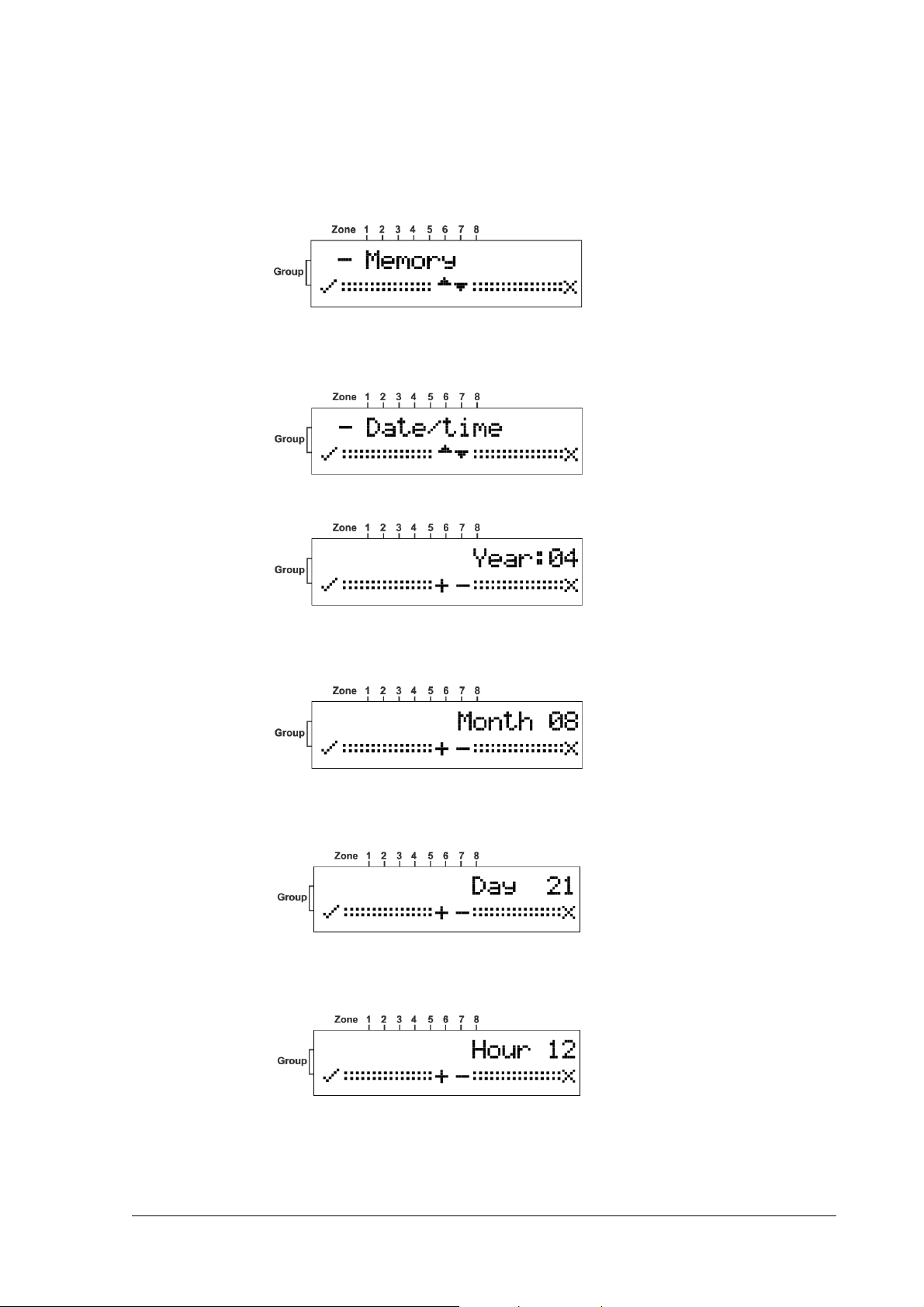
Setting the Clock
The following sections describe in detail how to set each mode.
1. From the Main
The Memory
2. Press the ▼ button to display the Date/Time
3. Press the ◄ button to confirm.
4. Press either the ▲ or ▼ buttons to select the Year
Main menu, press the ► button.
MainMain
Memory screen is displayed.
MemoryMemory
Date/Time screen.
Date/TimeDate/Time
Year.
YearYear
5. Press the ◄ button to set the Year
6. Press either the ▲ or ▼ buttons to select the Month
7. Press the ◄ button to set the Month
8. Press either the ▲ or ▼ buttons to select the Day
9. Press the ◄ button to set the Day
Year.
YearYear
Month.
MonthMonth
Day.
DayDay
Month.
MonthMonth
Day.
DayDay
10. Press either the ▲ or ▼ buttons to select the Hour
11
Hour.
HourHour
Page 12

11. Press the ◄ button to set the Hour
12. Press either the ▲ or ▼ buttons to select the Minutes
13. Press the ◄ button to set the Minutes
The time and date are updated and the Date/Time
Installer Mode
Accessing
Accessing the Installer Mode
AccessingAccessing
1. From the Main menu, press the ► button.
Hour.
HourHour
Minutes.
MinutesMinutes
the Installer Mode
the Installer Mode the Installer Mode
Minutes.
MinutesMinutes
Date/Time screen is displayed.
Date/TimeDate/Time
The Memory
Memory screen is displayed.
MemoryMemory
2. Press the ▲ button to display the Installer
3. Press the ◄ button to confirm.
The Password
Password screen is displayed.
PasswordPassword
The factory default password is 111
The factory default password is 111.
The factory default password is 111The factory default password is 111
4. Press the ▲ or ▼ buttons to enter the password.
Button
Button Description
ButtonButton
▲
Description
DescriptionDescription
Use for the ODD
ODD digits.
ODDODD
Installer screen.
InstallerInstaller
12
▼
Use for the EVEN
EVEN digits.
EVENEVEN
Page 13

Adding a
Adding a Wireless
Adding a Adding a
This mode is used for assigning a Group
a Group
Group and Zone
GroupGroup
tamper switch. This sends a signal to Merlin to learn and complete the device setup.
Wireless Device
Wireless Wireless
Zone and then on the selected device open the service cover and press the
ZoneZone
Device (Add Zone
DeviceDevice
(Add Zone))))
(Add Zone (Add Zone
Group and a Zone
GroupGroup
Zone for each detector or key. First assign
ZoneZone
1. Enter the Installer
See Accessing
2. Press the ◄ button to confirm.
The supervised mode uses an “Are You Alive
the devices are communicating with the unit.
OR
OR
OROR
Press either the ▲ or the ▼ buttons to toggle to Un
Installer mode.
InstallerInstaller
Accessing the
AccessingAccessing
the Installer
thethe
Installer Mode
InstallerInstaller
Mode on page 12 for instructions.
ModeMode
Are You Alive”””” time out mechanism to ensure that all
Are You AliveAre You Alive
Un----supervis
supervised
UnUn
supervissupervis
ed mode
eded
The units will be active but with no supervision.
3. Press the ◄ button to confirm.
Any Group
Group already selected displays an SSSS in that position.
GroupGroup
4. Press the ▲ or the ▼ buttons select a Group
5. Press the ◄ button to accept the group selection.
Group.
GroupGroup
13
Page 14
Any Zone
Zone already selected displays an SSSS in that position.
ZoneZone
The unit beeps while waiting a tamper signal sent from the selected device.
6. Learn the device in to the system by Opening the detector cover and operating the
tamper switch.
The device is registered and assigned the selected Group
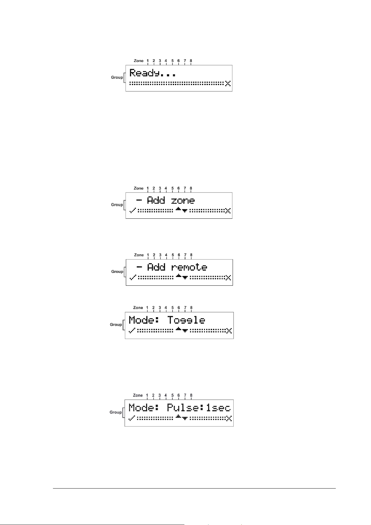
Adding a Remote Control
Adding a Remote Control key
Adding a Remote ControlAdding a Remote Control
1. Enter the Installer
See Accessing
2. Press the ▼ button to scroll to the Add Remote
Installer mode.
InstallerInstaller
Accessing the
AccessingAccessing
the Installer
thethe
Installer Mode
InstallerInstaller
key
key key
Mode on page 12 for instructions.
ModeMode
Add Remote Screen.
Add RemoteAdd Remote
Group and Zone
GroupGroup
Zone.
ZoneZone
3. Press the ◄ button to confirm.
Toggle will allow you to change the output state (on or off) by a single depression of
the remote key button.
OR
OR
OROR
Press the ▼ button to display the 1 second screen.
In this mode the output is activated for 1 seconds.
OR
OR
OROR
14
Page 15

Press the ▼ button to display the 3 second screen.
In this mode the output is activated for 3 seconds
OR
OR
OROR
Press the ▼ button to display the 1&2
1&2 screen.
1&21&2
NOTE
NOTE
NOTENOTE
If you choose this mode then the Relay screen opens enabling you to select an
output for one of the buttons on the remote key. You can then repeat this
procedure for selecting a different output for a second button on the remote.
4. Press the ◄ button to set the mode.
The Relay
Relay output screen opens.
RelayRelay
15
Page 16

5. Press the ▲ or ▼ buttons to choose an output.
Positions 1 to 7 are NC (dry contacts) and position 8 is a form C relay (NO/NC).
The Ready
Ready screen opens and the unit beeps waiting for a remote key signal.
ReadyReady
6. Press a button on the remote key unit.
The remote key is registered and the Add remote
Clear Zone
Clear Zone
Clear ZoneClear Zone
1. Enter the Installer
See Accessing
2. Press the ▼ button to scroll to the Add Remote
Installer mode.
InstallerInstaller
Accessing the
AccessingAccessing
the Installer
thethe
Installer Mode
InstallerInstaller
Mode on page 12 for instructions.
ModeMode
Add remote screen is displayed.
Add remoteAdd remote
Add Remote Screen.
Add RemoteAdd Remote
16
3. Press the ◄ button to confirm.
4. Press the ▲ or ▼ buttons to choose a Group
5. Press the ◄ button to set the Group
6. Press the ▲ or ▼ buttons to select a Zone
Group.
GroupGroup
Group.
GroupGroup
Zone.
ZoneZone
Page 17

7. Press the ◄ button to set the Zone
The unit will beep twice and the Zone
Clear Re
Clear Remote
Clear ReClear Re
1. Enter the Installer
See Accessing
mode.
2. Press the ▼ button to scroll to the Clear Remote
mote
motemote
Installer mode.
InstallerInstaller
Accessing the
AccessingAccessing
the Installer
thethe
Installer Mode
InstallerInstaller
Zone.
ZoneZone
Zone is cleared.
ZoneZone
Mode on page 12 for instructions on how to enter this
ModeMode
Clear Remote Screen.
Clear RemoteClear Remote
3. Press the ◄ button to confirm.
4. Press the ▲ or ▼ buttons to select a Remote
The unit will beep twice and the Remote
Remote.
RemoteRemote
Remote is cleared.
RemoteRemote
17
Page 18

Chang
Changing the
ChangChang
1. Enter the Installer
ing the Password
ing theing the
Password
Password Password
Installer mode.
InstallerInstaller
See Accessing
Accessing the
AccessingAccessing
mode.
2. Press the ▼ button to scroll to the Change Password
3. Press the ◄ button to confirm.
4. Enter the new Password
For example, for a password of 123 press in sequence the following buttons:
▲ ,▼ ▼, ▲ ▲ ▲
5. Press the ◄ button to confirm the new password.
The Change Password
Change Password screen is displayed.
Change PasswordChange Password
the Installer
Installer Mode
thethe
InstallerInstaller
Password.
PasswordPassword
Mode on page 12 for instructions on how to enter this
ModeMode
Change Password Screen.
Change PasswordChange Password
6. Record the password and store in a safe place.
Checking
Checking the RSSI
CheckingChecking
1. Enter the Installer
See Accessing
2. Press the ▼ button to scroll to the RSSI
the RSSI (Radio signal strength)
the RSSI the RSSI
Installer mode.
InstallerInstaller
Accessing the
AccessingAccessing
(Radio signal strength)
(Radio signal strength) (Radio signal strength)
the Installer
Installer Mode
thethe
InstallerInstaller
Mode on page 12 for instructions.
ModeMode
RSSI Screen.
RSSIRSSI
18
Page 19
3. Press the ◄ button to confirm.
The RSSI screen opens.
4. Either operate a tamper switch of one of the devices or press the remote key button.
The signal strength is displayed on the screen.
5. Press the ◄ button to clear the screen.
6. Press the ► button to exit this mode.
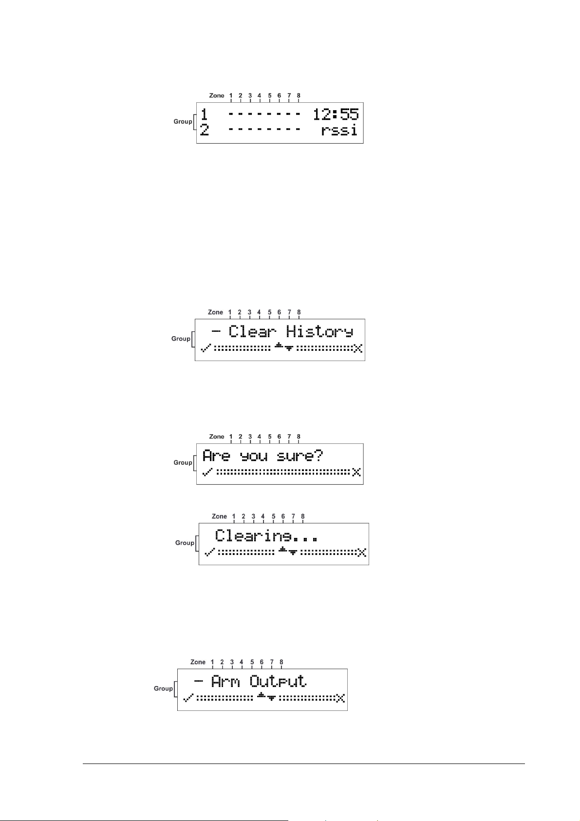
Clear History
Clear History
Clear HistoryClear History
1. Enter the Installer
See Accessing
mode.
2. Press the ◄ button to confirm.
Installer mode.
InstallerInstaller
Accessing the
AccessingAccessing
the Installer
thethe
Installer Mode
InstallerInstaller
Mode on page 12 for instructions on how to enter this
ModeMode
3. Press the ◄ button to confirm acceptance.
The Log Events is cleared.
Arm To Output
Arm To Output
Arm To OutputArm To Output
1. Enter the Installer
See Accessing
Accessing the
AccessingAccessing
Installer mode.
InstallerInstaller
the Installer
Installer Mode
thethe
InstallerInstaller
Mode on page 12 for instructions on how to enter this mode.
ModeMode
2. Press the ◄ button to confirm.
19
Page 20

3. Press the ▲or ▼ button to choose the Output you want to assign for arming the C.P
.
4. Press the ◄ button to confirm.
NOTE
NOTE
NOTENOTE
While you assign one Output to Arm this Output will not activated if one of the
detectors is in Alarm and a long beep will be heard to indicate that the Arm isn't
allowable. If all zones are sealed the output will activate and few beeps will heard
for success.
Buzzer T
Buzzer Tie
Buzzer TBuzzer T
1. Enter the Installer
See Accessing
Accessing the
AccessingAccessing
2. Press the ◄ button to confirm.
3. Press the ▲or ▼ button to choose Yes or No .
4. Press the ◄ button to confirm.
ie
ieie
Installer mode.
InstallerInstaller
the Installer
Installer Mode
thethe
InstallerInstaller
Mode on page 12 for instructions on how to enter this mode.
ModeMode
20
NOTE
NOTE
NOTENOTE
While you assign one Outputs to buzzer ,every Output activation will activate the
buzzer until the Output will restore.
Page 21

Remotes
Remotes Log
RemotesRemotes
Log
Log Log
1. Enter the Installer
See Accessing
Accessing the
AccessingAccessing
2. Press the ◄ button to confirm.
5. Press the ▲or ▼ button to choose Yes or No .
6. Press the ◄ button to confirm.
NOTE
NOTE
NOTENOTE
If you will choose yes for Remotes to Log all the remotes activation will be recorded
on the Log Event.
Installer mode.
InstallerInstaller
the Installer
Installer Mode
thethe
InstallerInstaller
Mode on page 12 for instructions on how to enter this mode.
ModeMode
Version
Version
VersionVersion
1. Enter the Installer
See Accessing
2. Press the ▼ button to scroll to the version
3. Press the ◄ button to confirm.
Installer mode.
InstallerInstaller
Accessing the
AccessingAccessing
the Installer
thethe
Installer Mode
InstallerInstaller
Mode on page 12 for instructions.
ModeMode
version Screen.
versionversion
21
Page 22

Setting the Unit Defaults
Setting the Unit Defaults
Setting the Unit DefaultsSetting the Unit Defaults
1. Enter the Installer
See Accessing
2. Press the ▼ button to scroll to the Defaults
3. Press the ◄ button to confirm.
4. Press the ◄ button to confirm acceptance.
Installer mode.
InstallerInstaller
Accessing the
AccessingAccessing
the Installer
thethe
Installer Mode
InstallerInstaller
Mode on page 12 for instructions.
ModeMode
Defaults Screen.
DefaultsDefaults
22
The unit is formatted.
Formatting has completed successfully and the Main
now returned to its factory default condition.
Main screen is displayed. The unit is
MainMain
Page 23

Functions
NOTE
NOTE
NOTENOTE
While the Merlin Pro is in normal operation it must display the main screen or
reported events will be ignored.
Function Description
Outputs
Outputs Outputs 1 to 8 and Tamper are dry contact
OutputsOutputs
(Not relative to GND)
Outputs 1 to 7
Outputs 1 to 7 are Normally closed.
Outputs 1 to 7Outputs 1 to 7
Output 8
Output 8: Relay with three terminals for, NO, NC, and C
Output 8Output 8
(C-Common, NC- Normally closed, NO- Normally open)
Tamper
Tamper is normally closed.
TamperTamper
STA Input
STA Input When this Input is Low
STA InputSTA Input
Low it indicates that the Control Pane
LowLow
Control Panel is armed. In
Control PaneControl Pane
this mode all the events are recorded in the Log buffer.
Alarm event
Alarm event Displayed on the LCD screen and activates the assigned output to Open
Alarm eventAlarm event
Open
OpenOpen
for 3 seconds.
In Armed
Armed mode the event is displayed until disarmed.
ArmedArmed
Tamper Event
Tamper Event Activates the tamper and then assigns Output to Open until restored.
Tamper EventTamper Event
Recorded in the event log.
Supervis
Supervision
SupervisSupervis
missing
missing
missingmissing
ion
If a detector is programmed as Supervised and the Merlin does NOT
ion ion
receive any transmission from it for more than 120 minutes it indicates
Supervision
Supervision missing by beeping every 1 minute as a warning and will
SupervisionSupervision
record it on the events log.
Detector
Detector Low
DetectorDetector
Battery
Battery
BatteryBattery
Low
When a detector transmits that it has Low Batter
Low Low
Low Battery the Merlin Pro will
Low BatterLow Batter
record it in the events log and will beep every 1-minute.
NOTE
NOTE
NOTENOTE
The warning beeps will not sound while viewing the event log or by pressing the ◄
key. The warning beeps will start again after the next Disarm.
23
Page 24

Page 25

Technical Specifications
Input Voltage
Input Voltage 10 to 15V DC
Input VoltageInput Voltage
Current Consumption
Current Consumption Max. 130mA
Current ConsumptionCurrent Consumption
Outputs 1 to 7
Outputs
Outputs
OutputsOutputs
STA Input
STA Input Applied low in the armed condition activates memory log.
STA InputSTA Input
Real Time Clock
Real Time Clock Real time clock with backup battery lasting for 2000 hours or
Real Time ClockReal Time Clock
Wi
Wireless Detectors
reless Detectors Up to 64 detectors (8 per group)
WiWi
reless Detectorsreless Detectors
Outputs 1 to 7
Outputs 1 to 7Outputs 1 to 7
Opto MOSFET, Contact Resistance 17 ohm
Maximum Current - 100mA
Output 8
Output 8
Output 8Output 8
Relay, Contact Resistance- 0 ohm
Maximum Current - 1A
Tamper
Tamper
TamperTamper
Opto MOSFET, Contact Resistance- 17 ohm
Maximum Current - 100mA
five years.
Wireless Remotes
Wireless Remotes Up to 256 remote keys can be connected
Wireless RemotesWireless Remotes
Log Buffer (event)
Log Buffer (event) 256 records (FIFO)
Log Buffer (event)Log Buffer (event)
Receiver Sensitivity
Receiver Sensitivity Up to 300 m in open areas
Receiver SensitivityReceiver Sensitivity
25
Page 26

CROW ELECTRONIC ENGINEERING LTD. (Crow) WARRANTY POLICY CERTIFICATE
This Warranty Certificate is given in favor of the purchaser (hereunder the "Purchaser
from its authorized distributor.
Crow warrants these products to be free from defects in materials and workmanship under normal use and service for a period of 24
months from the last day of the week and year whose numbers are printed on the printed circuit board inside these products
(hereunder the "Warranty Period
Subject to the provisions of this Warranty Certificate, during the Warranty Period, Crow undertakes, at its sole discretion and subject to
Crow's procedures, as such procedures are form time to time, to repair or replace, free of charge for materials and/or labor, products
proved to be defective in materials or workmanship under normal use and service. Repaired products shall be warranted for the
remainder of the original Warranty Period.
All transportation costs and in-transit risk of loss or damage related, directly or indirectly, to products returned to Crow for repair or
replacement shall be borne solely by the Purchaser.
Crow's warranty under this Warranty Certificate does not cover products that is defective (or shall become defective) due to: (a)
alteration of the products (or any part thereof) by anyone other than Crow; (b) accident, abuse, negligence, or improper maintenance;
(c) failure caused by a product which Crow did not provide; (d) failure caused by software or hardware which Crow did not provide;
(e) use or storage other than in accordance with Crow’s specified operating and storage instructions.
There are no warranties, expressed or implied, of merchantability or fitness of the products for a particular purpose or otherwise,
which extend beyond the description on the face hereof.
This limited Warranty Certificate is the Purchaser's sole and exclusive remedy against Crow and Crow's sole and exclusive liability
toward the Purchaser in connection with the products, including without limitation - for defects or malfunctions of the products. This
Warranty Certificate replaces all other warranties and liabilities, whether oral, written, (non-mandatory) statutory, contractual, in tort
or otherwise.
In no case shall Crow be liable to anyone for any consequential or incidental damages (inclusive of loss of profit, and whether
occasioned by negligence of the Crow or any third party on its behalf) for breach of this or any other warranty, expressed or implied,
or upon any other basis of liability whatsoever. Crow does not represent that these products can not be compromised or
circumvented; that these products will prevent any person injury or property loss or damage by burglary, robbery, fire or otherwise; or
that these products will in all cases provide adequate warning or protection.
Purchaser understands that a properly installed and maintained product may in some cases reduce the risk of burglary, fire, robbery or
other events occurring without providing an alarm, but it is not insurance or a guarantee that such will not occur or that there will be
no personal injury or property loss or damage as a result.
Consequently, Crow shall have no liability for any personal injury; property damage or any other loss based on claim that these
products failed to give any warning.
If Crow is held liable, whether directly or indirectly, for any loss or damage with regards to these products, regardless of cause or
origin, Crow’s maximum liability shall not in any case exceed the purchase price of these products, which shall be the complete and
exclusive remedy against Crow.
Warranty Period").
Warranty PeriodWarranty Period
Purchaser") purchasing the products directly from Crow or
PurchaserPurchaser
ISRAEL
ISRAEL:
ISRAELISRAEL
12 Kineret St.,
AirPort City 70100
Tel:
Tel: 972-3-9726000
Tel:Tel:
Fax:
Fax: 972-3-9726001
Fax:Fax:
EEEE----mail:
mail:
mail:mail:
support@crow.co.il
ITALY:
DEATRONIC
VIA Giulianello 4/14
00178 ROMA, ITALY
Tel:
Tel: +39-0676-12912
Tel:Tel:
Fax:
Fax: +39-0676-12601
Fax:Fax:
EEEE----mail:
mail:
mail:mail:
info@deatronic.com
USA
USA:
USAUSA
2160 North Central Road,
Fort Lee, N.J. 07024
Tel:
Tel: 1-800-GET CROW
Tel:Tel:
(201) 944 0005
Fax:
Fax: (201) 944 1199
Fax:Fax:
EEEE----mail:
mail:
mail:mail:
support@crowelec.com
LATIN AMERICA:
LATIN AMERICA:
LATIN AMERICA:LATIN AMERICA:
CROW LATIN AMERICA
5753 NW 151ST.Street
MIAMI LAKES,
FL 33014 – USA
Tel: +1-305-823-8700
Fax: +1-305-823-8711
EEEE----mail:
mail:
mail:mail:
sales@crowlatinamerica.com
AUSTRALIA
AUSTRALIA:
AUSTRALIAAUSTRALIA
429 Nepean HWY Brighton East
Vic 3187
Tel: 61-3-9596 7222
Fax: 61-3-9596 0888
EEEE----mail:
mail:
mail:mail:
crow@crowaust.com.au
POLAND:
POLAND:
POLAND: POLAND:
VIDICON SP. ZO. O.
15 Povazkowska St.
01 – 797 Warsaw
Tel: 48 22 562 3000
Fax: 48 22 562 3030
EEEE----mail:
mail:
mail:mail:
vidicon@vidicon.pl
26
 Loading...