

Page 1
1 2 3
GBD-PLUS
COMPACT
GLASS BREAK DETECTOR
ELECTRONIC ENGINEERING LTD.
INSTALLATION INSTRUCTIONS
P/N 7101352
Ver. G A.Y.
The GBD-PLUS is the ultimate answer for all
those tired of false alarms. It listens f or
sounds of breaking glass, whic h produc e two
sequential signals of dif f erent frequencies.
The unique phased frequency detection
circuitry of this det ector allows detection of
both shock signal and the strong signal of
glass breakage creating a “fals e al arm free”
glass break detector.
The detector does not need to be attached to
the window, providing volume protection, and
allowing you to protect several windows with
one detector.
FEATURES
• Shock and/or break age selectable
• Analyzes two frequencies
• Unique signal analysi s ignores
environmental disturbances
• Memory LED
• Sensitivity adjustment
• New ultra compact design
• Flush mount i nstallation (option)
• Outstanding detect i on range and reliabilit y
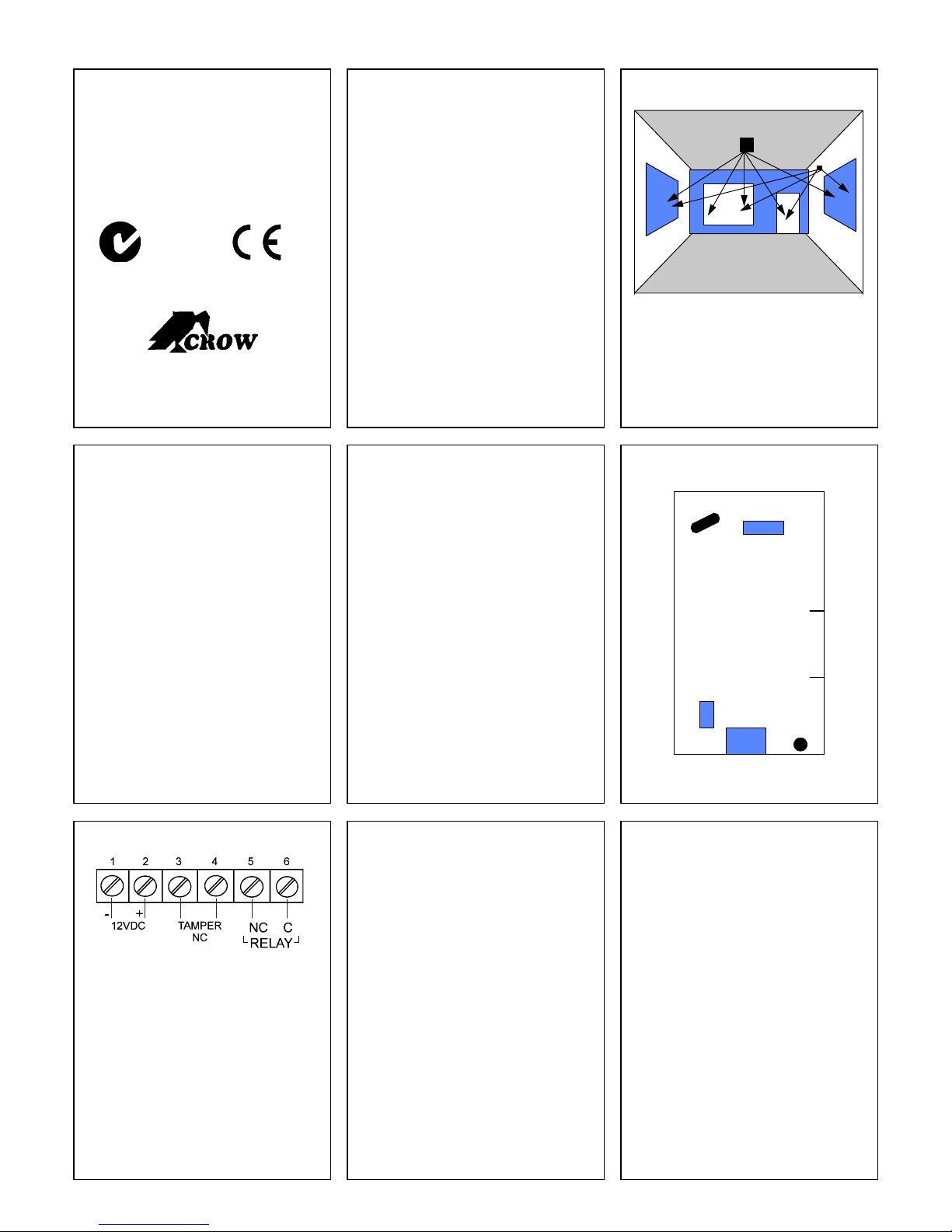
FIG. 1 - MOUNTING
The detector offers flexible ins tallation. It can
be either ceiling mounted or wall m ounted as
shown in the figure above.
4 5 6
MOUNTING LOCATION ( See FIG. 1 )
• I f heavy blinds or curtains cover the glass,
you must locate the det ector behind the
blinds on the window frame or above it,
otherwise the blinds might block the
sound. Make sure to test the uni t
thoroughly for proper detection.
• I nstall the detector in a direct l i ne of sight
with the protected glass.
• Do not mount the unit in front of air duc t s,
or close to bells (measuring 0.5m (or
larger) in diameter).
• For a few protected glasses in one room,
locate the detector in optimal distance
from them to achi eve t he best detection.
Note: for symmetrical cover of the detection
area it is recommended to place the
detector on the ceiling.
MOUNTING THE DETECTOR ( FIG. 2 )
1. Use a small screwdriver to push the prong
on top of the case and open the case.
2.
Snap out the detector PCB.
3. Insert the wires through the wiring hole (B).
4. Use the mounting holes (A) to mount the
detector.
5. Connect the wires to the termi nal . (See
Terminal Connections)
6. Reinstall the detector P CB .
7. Close the case.
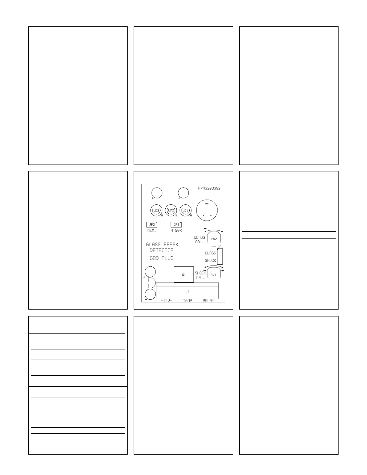
JUMPERS ( FIG. 4 )
• JP1 - Shock / Glass selec tor for detection
calibration.
• JP2 – Memory LED control.
• JP3 - Reduces the sensitivity of sound
detection by 50%.
FIG. 2 - THE BACK COVER
A
A
B
7 8 9
FIG. 3 - TERMINAL BLOCK
TERMINAL BLOCK CONNECTIONS
Terminal 1 - Marked - ( GND )
Connect to ground of the control panel.
Terminal 2 - Marked + ( +12V )
Connect to the positive Volt age output of 9-16
Vdc
source (usually from the alarm control unit)
Terminals 3 & 4 - Marked TAMPER
If a Tamper function is required connect these
terminals to a 24hour normally closed protective zone
in the control unit. If the front cover of the detector is
opened, an immediate alarm signal will be sent to the
control unit.
Terminals 5 & 6 - Marked RELAY
These are the output relay contacts of the detector.
Connect to the control at zone input.
THE CALIBRATION TOOL ( * )
The Simulator/Tester & Calibration tool is
especially designed to check phased
frequency glass break detect o rs.
Since the detector will react to the high
frequency breakage sound only when it
comes sequentially after a low frequency
SHOCK sound, this device i s necessary to
check for proper operation of the GB D-P LUS
without actually breaking the glass .
Manual mode:
In this mode, the Simulat or will emit the high
frequency sound of breaking glass f o r " Gl ass"
adjustment.
Automatic mode:
In order to simulate breaki ng gl ass, place the
Simulator on the surface of the protected
glass, and gently hit it with your hand. T he
Simulator will then emit the sound of breaking
glass. Be careful not t o break the glass while
testing the detector.
∗ It is recommended to use simulator CROW
P/N: 0040011
TESTING THE DETECTOR
First use the Sim ul at or i n manual mode to
simulate the noise of gl ass breaking. Check
that the yellow LED is ON. If it does not light,
the sensitivity cali b rat i on i s necessary (See
Sound Calibration).
Now use your hand or a padded object to
carefully strike the glass. If the green LED
does not light, adjust as necessary (See
Shock Calibration).
Now use the Simulator in automatic mode
and check that the red LED light s. If the red
LED is ON, your detector is worki ng properl y.
Otherwise try adjusting the sound and shock
setting until the red LED lights.
N345
Page 2
10 11 12
GLASS BREAK ADJUSTMENT
To adjust the glass break s etting
(increase/decrease sensi tivity) place the
jumper JP1 according the GLASS marking
(connecting the middle pin with the upper pin)
- (See Fig. 4) Green LED is const ant l y ON.
Now you can adjust the sensitivit y by rotating
the upper potentiometer (marked as GLASS
CAL. - see Fig. 4).
Operate the Sound Break Simulator and
rotate the potentiometer clock-wise to
increase sensitivit y, and counter-clock-wise to
decrease sensitivity unt i l the Yellow and Red
LED’s are illuminating for each glass break
sound. Remember that rotating the
potentiometer will have no effect upon the
settings if the m i ddl e pi n of JP1 is not
connected to the upper pin.
Note
• When the jumper is set for GLASS
adjustment, only the hi gh frequency sound
of breaking glass is detec ted.
SHOCK ADJUSTMENT
To adjust the shock setting
(increase/decrease sensi tivity) place the
jumper JP1 according the SHOCK marking
(connecting the middle pin with the lower pin)
- (See Fig. 4) Yellow LED is const antly ON.
Now you can adjust the sensitivit y by rotating
the lower potentiometer (mark ed as SHOCK
CAL. - see Fig. 4).
Hit gently on the protected glass and rotate
the potentiometer clock-wise to increase
sensitivity, and count er-clock-wise to
decrease sensitivity unt i l t he Green and Red
LED’s are illuminating for each hit.
Remember that rotating the potentiometer will
have no effect upon the settings if the middle
pin of JP1 is not connected to the lower pin.
Note
• When the jumper i s set for SHOCK
adjustment, only the l ow frequenc y of the
shock signal prior to glas s breakage is
detected.
THE MEMORY FUNCTION
The alarm memory function allows the
identification of an alerti ng detector out of
multiple detectors connected to one (or the
same) zone of the control panel.
To enable this function, S et ON jumper JP2
(MEM) (connected on both pins - See Fig. 4)
In case of an alarm, the Red LED will stay
ON until memory function is reset.
To reset the memory function, switch OFF
(disconnect) the voltage wire (+12V) from the
TERMINAL BLOCK for minimum 15 seconds
then switch on (reconnect) voltage wire
(+12V).
(The control panel key ON/OFF can be used
for this application if i t control the voltage
(+12V).
SENSITIVITY SETTING
For some installat i ons you may find that GBDplus is too sensiti ve. Use JUMPER JP3 to
decrease sensitivity t o 50%.
JP3 OPEN - 100% sensit i vity
JP3 CONNECTED - 50% sensi t i vi ty
13 14 15
FINAL TESTING
• Make sure to disconnect the j umper at
JP1. When the j umper is disconnected,
the detector will detect both shock and
sound frequencies.
• To ensure maximum protec tion against
false alarms, ac tivate any device in the
area, which might automati cally cycle
pumps, generators, heati ng/ ai r
conditioning units, etc . If the cycling
devices trigger an alarm, mount the unit in
a different location.
FIG. 4 - PCB Layout
WIRE SIZE REQUIREMENTS
Use #22 AWG (0.5mm) or wires with a larger
diameter. Use the foll owing table to determine
required wire gauge (diameter) and length of
wire between the detector and the control
panel.
Wire Length m 200 300 400 800
Wire Diameter mm .5 .75 1.0 1.5
Wire Length ft 800 1200 2000 3400
Wire Gauge # 22 20 18 16
16 17 18
TECHNICAL SPECIFICATIONS
Power Input
9 - 16 Vdc
Current Consumption
Standby: 22mA at 12Vdc
Active: 25mA at 12Vdc
Detection Range
10m (33ft), Adjustable
Dimensions
78mm x 51mm x 21mm
(3.07 `` x 2.01`` x 0.83)
Mounting
Ceiling or Wall
Alarm Output Relay
N.C 50mA/24Vdc with
27 Ohm in line resistor
Tamper Switch
N.C 50mA 24Vdc with
10 Ohm in line resistor
Operating Temperature -20°C to 50°C
Range (-4°F to 122°F)
Operating Humidity 95% max relative humidity
Range non condensing
Storage Temperature -30°C to 70°C
Range (-22°F to 158°F)
Electro condenser
microphone
RFI Protection 30V/m 10 -1000MHz
EMI Protection 50,000V electrical
interference from lightning
CROW reserves the rights to change specifications
without prior notice
CROW ELECTRONIC ENGINEERING LTD. ("Crow") –
WARRANTY POLICY CERTIFICATE
This Warranty Certi ficate is given in favor of the purchaser (hereunder the "Purchaser") purchasing the
products directly f rom Crow or from its authorized distributor.
Crow warrants these produc t s t o be free f rom defec ts in m aterial s and work mans hip under normal use
and service for a period of 24 months from the last day of the week and year whose numbers are
printed on the printed circuit board inside these products (hereunder the "Warranty Period").
Subject to the provisi ons of t his Warranty Certifi cate, during the Warranty Period, Crow undertakes, at
its sole dis cretion and subject t o Crow's procedures, as suc h procedures are form time to t ime, to
repair or replace, free of charge for material s and/ or labor, produc ts prov ed to be defect iv e in materials
or workmanship under normal use and servic e. Repaired product s shal l be warranted for the remainder
of the original Warranty Period.
All transportation cos ts and in-trans it risk of loss or damage related, directly or indirect ly, to products
returned to Crow for repair or replacement shal l be borne solely by the Purchaser.
Crow's warranty under this Warranty Certificate does not cov er products that is defec tive (or shall
become defective) due t o: (a) alteration of the product s (or any part thereof) by any one other than
Crow; (b) accident, abuse, negligence, or im proper maint enance; (c) f ail ure caus ed by a produc t whi ch
Crow did not provide; (d) failure caus ed by s oft ware or hardware which Crow did not provide; (e) use or
storage other than in accordance with Crow’ s specified operating and storage instructions.
There are no warranties, expressed or impl ied, of merchantability or fitness of the products for a
particular purpose or otherwise, whi ch extend beyond the description on t he face hereof.
This limited Warrant y Certificate i s the Purchaser's s ole and exclusive remedy against Crow and
Crow's sole and exclusive liability toward the Purchaser in connection with the products , including
without limitation - for def ects or malfunc tions of the produc ts. This Warrant y Certificate replaces all
other warranties and liabilities, whether oral, written, (non-mandatory) statutory, contrac tual, in tort or
otherwise.
In no case shall Crow be liable to any one for any consequenti al or incidental damages (inc lusive of
loss of profit , and whether oc casioned by negligence of t he Crow or any third party on its behalf) f or
breach of this or any other warranty, expressed or implied, or upon any other bas is of liability
whatsoever. Crow does not represent t hat these product s can not be com promised or circ umvented;
that these products will prevent any person injury or property loss or damage by burglary, robbery, fire
or otherwise; or that these produc ts will in all cases provide adequate warning or protection.
Purchaser understands that a properly instal led and maintained product may in some c ases reduce the
risk of burglary, fire, robbery or other events occurring without providing an alarm, but it is not
insurance or a guarantee that such will not occur or that there will be no personal injury or property loss
or damage as a result.
Consequently, Crow shall have no l iability for any personal injury; property dam age or any other loss
based on claim that these produc ts failed to give any warning.
If Crow is held liable, whether di rectly or indirectly, for any loss or damage with regards to these
products, regardless of caus e or origin, Crow’s maximum liability shall not in any case exceed the
purchase price of these product s, which shall be the complet e and exclusive remedy against Crow.
7101352_G
CROW ELECTRONIC ENGINEERING LTD.
12 Kineret St.
Airport City, 70100 Israel
Tel. +972 3 9726000
Fax. +972 3 9726001
sales@crow.co.il
support@crow.co.il
www.thecrowgroup.com
CROW LATIN AMERICA USA INC.
7200 NW 19 st.
Suite 307
Miami FI 33126, USA
Tel. +305 513 4001
Fax. +305 513 4005
rejane@crowlatinamerica.com
www.crowlatinamerica.com
ARROWHEAD ALARM PRODUCTS
344B, Rosedale Road
Park Farm Industrial Estate
Albany, Auckland
New Zealand
Tel. +64 9 414 0085
Fax. +64 9 414 0088
www.aap.co.nz
These instructions supersede all previous
issues in circulation prior to February 2012.
 Loading...