

Page 1
INSTALLATION INSTRUCTIONS
FW NEO 9F
WIRELESS PIR WITH PET IMMUNITY UP TO 20 Kg
PRODUCT FEATURES
The
FW NEO 9F is an advanced, fully supervised lowcurrent wireless PIR that includes a FreeWave
transmitter. Both transmitter and detector circuits are
powered by long life Lithium battery.
Each FW NEO 9F has a unique ID code (This code is
impossible to reproduce). Compatible FreeWave
receivers are designed to “learn” specific IDs and
respond only to them.
Following detection, FW NEO 9F triggers the on-board
transmitter that transmits its specific FreeWave ID
followed by an alarm signal and status designators for
battery condition. If detector cover is removed Tamper
Event triggers the on-board transmitter.
Alarm and other data are forwarded to the alarm
control panel. A periodic test transmission for
supervision purpose takes place automatically once in
7 min. The receiver is informed that the particular
detector is taking an active part in the wireless security
system.
The FW NEO 9F has unique Alarm Power Saver (APS)
mechanism that enables transmitter activation only 2
min after the last movement has been detected.
• State-of-the-art wireless security system
• Low current
ASIC PIR Technology
• Powered by a 3Volt Lithium battery
• Battery life : up to 4 years
• Built in Automatic Power Saver (APS)
• Frequency Band: 916.5MHz
• Low Battery condition signal transmission
• Test mode for PIR coverage and RF signal.
• Range up to 300 m at free space.
• Height installation calibration free (1.5m - 3.6m).
• Unique ID number
The FW NEO 9F provides pet immunity up to 20Kg. Pet
active bellow 1m.
The Wireless PIR transmits the following events data:
SUPERVISION - a periodical transmission.
Every 7 min indicates detector’s presence.
ALARM – alarm transmission triggered by PIR
intrusion detection.
LOW BAT – Whenever the battery reaches a pre-set
low level (2.4V) Battery Low signal will be sent with the
next message (Supervision, Alarm, etc.)
TAMPER – Whenever the FW NEO 9F cover is
removed or the unit teals from the wall, a message
"Tamper" will be transmitted.
APS
The unique APS (Automatic Power Saver) function built
in the detector enables a battery life span up to four
years. The detector will transmit only when the last even
t
has occurred more than 2 minutes prior to the current
one.
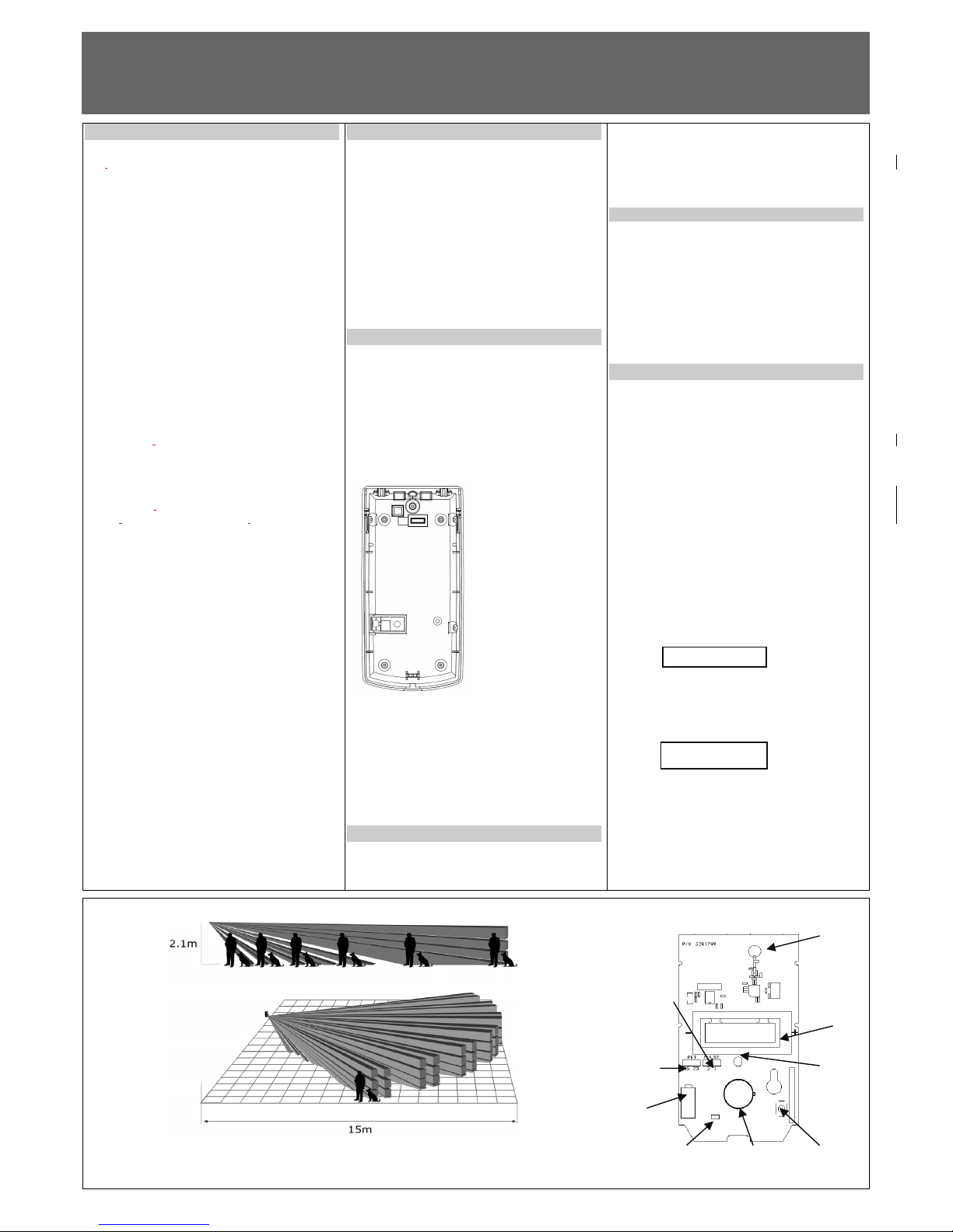
SELECT MOUNTING LOCATION
Choose a location most likely to intercept an intruder.
(Our recommendation is a corner installation). See
detection pattern – fig.2. The quad-element high
quality sensor detects motion crossing the beam; it is
slightly less sensitive detecting motion toward the
detector.
Recommended mounting height – 1.8m-2.4m.
AVOID THE FOLLOWING LOCATIONS
• Facing direct sunlight.
• Facing areas that may change temperature
rapidly.
• Areas where there are air ducts or
substantial airflows.
The FW NEO 9F performs better when provided with a
constant and stable environment.
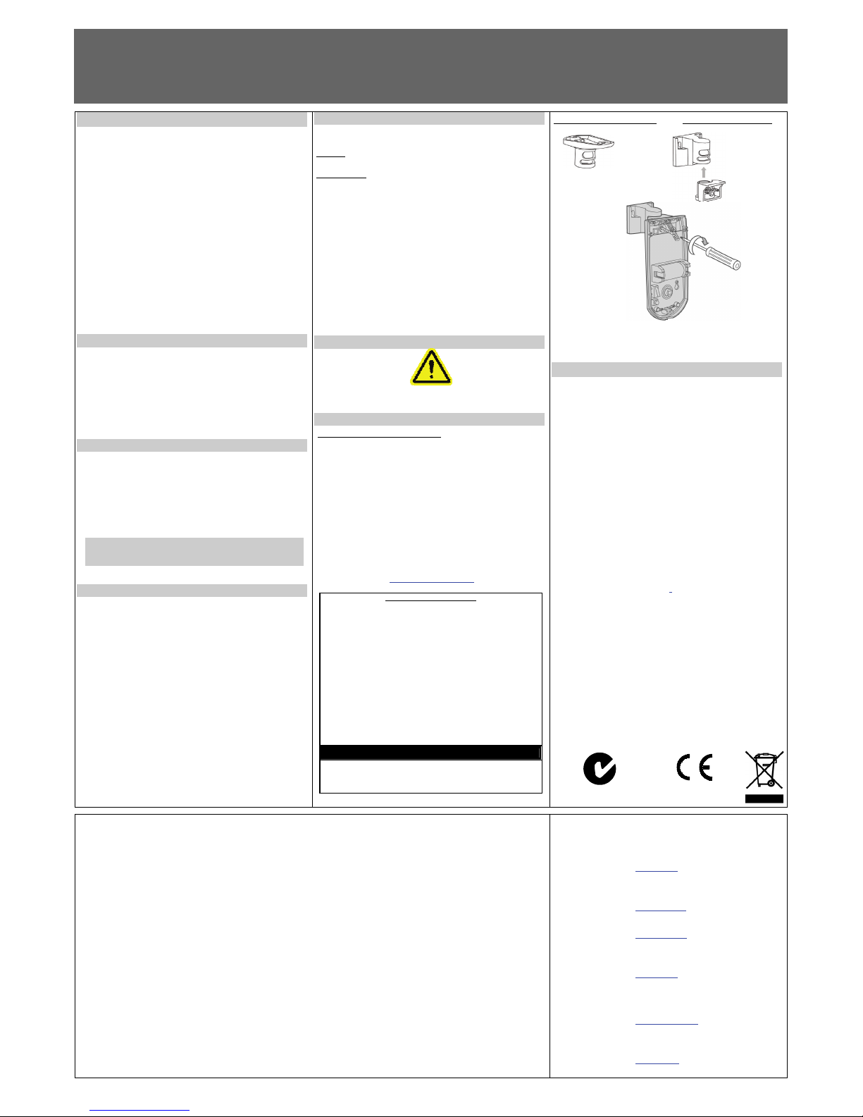
DETECTOR INSTALLATION
The detector can either be wall or corner mounted.
If ceiling or special wall mounting is required, use the
optional bracket base. Refer to bracket description.
(See fig. 4).
1. To remove the front cover, unscrew the holding screw
and gently raise the front cover.
2. To remove the PC board, carefully unscrew the
holding screw located on the PC board.
3. Break out the desired holes for proper installation.
Fig. 1
4. Mount the detector base to the wall, corner or ceiling.
(For option with bracket see fig.4).
5. Reinstall the PC board by fully tightening the holding
screw.
6. Install battery in the battery holder according polarity.
7. Replace the cover by inserting it back in the
appropriate closing pins and screw in the holding
screw.
RSSI-RF SIGNAL INDICATION
The control panel has “RF Signal quality Indication”
for each transmitter in order to help the installer to
define best location for the detector from RF point
of view.
The indication value is between 1 and 100, where
100 is the best RF received signal. If the RSSI
indication is less then 30, it is a sign for weak RF
link, try to find a better installation for the PIR.
NOTE: See control panel installation instruction.
ID REGISTRATION
Refer to the system receiver’s installation instructions
and follow the procedure given there for “learning”
detector IDs.
Perform transmission by pressing and releasing
tamper switch for learning it by the control panel
receiver.
Make sure that the receiver is at learning mode according to control panel installation instruction.
NOTE: It is recommended to power up the detector and
let the system receiver “learn” the detector’s ID before
actual installation.
TESTING THE DETECTOR
TEST PUSH BUTTON
Push Button is located at the lower left side of the
detector. This button (switch) is used to activate the
walk and RF transmission test of the detector.
WALK TEST
Push the Test button for 1 sec and release, the LED
will blink 3 times, the LED and a Transmission will
activate on the every detection.
The test mode period is 2 min; at the end of the test
mode the LED will blink fast 4 times to indicate the end
of the Test.
ALARM TRANSMISSION TEST
Pressing Push Button for at least 3.0 sec enables the
alarm transmission test feature, which activates 11
transmission signals at 6 sec intervals (total test time
about 1 min).
Please check, that the receiver unit indicates 11
events.
This test enables to activate the alarm transmission
immediately, and bypass the APS 2 minutes limitation.
To check this function it is necessary to verify that the
control panel display shows
X- zone number from which the massage received.
Tamper transmission test.
Change of the tamper switch state will cause tamper
transmissions. Verify on the control panel that display
shows
Transmission range test.
By Alarm transmission test (Pressing Push Button for
more then 3.0 sec) it’s enable to check the RF
transmission quality (RSSI). Special indication at the
control panel displays continuously the received RF
signal quality.
Fig.2
Fig.3
7101799_A - 1 -
B. Use for flat wall
mounting
C. Corner
mounting - use
all 4 holes.
Sharp left or
right angle
mounting - use
2 holes (top
and bottom)
D. For bracket
mounting
E. For back
tamper
D
B B
B
B
C
C
C
Trouble Zone # X
C E
ANTENNA
BATTERY
2/3AA 3V
LED
TEST
PUSH
BUTTON
PYROSENSOR
PET
IMMUNITY
ADJUSTMENT
JUMPER
BACK
TAMPER
(PS)
SENSITIVITY
ADJUSTMENT
JUMPER
Page 2
INSTALLATION INSTRUCTIONS
FW NEO 9F
FREEWAVE™ WIRELESS PIR WITH PET IMMUNITY UP TO 20 Kg
OPERATION
The Wireless PIR transmits the following events data:
SUPERVISION - a periodical transmission.
Every 7 min indicates detector’s presence.
ALARM – alarm transmission triggered by PIR
intrusion detection.
LOW BAT – Whenever the battery reaches a pre-set
low level (2.4V) Battery Low signal will be sent with the
next message (Supervision, Alarm, etc.
TAMPER – Whenever the unit cover is removed or the
unit’s cover is put back, a message will be transmitted
with “Tamper” signal.
APS
The unique APS (Automatic Power Saver) function built
in the detector enables a battery life span up to four
years. The detector will transmit only when the last
event has occurred more than 2 minutes prior to the
current one.
PIR SENSITIVITY ADJUSTMENT
Jumper “Sensitivity Adjustment” use for setting the
PULSE count function in order to provide PIR
sensitivity control according to the environment.
Position Right– “1”-High sensitivity
For stable environments.
Position Left – “2” – Low sensitivity
For harsh environments.
PET IMMUNITY SETTING
Jumper “Pet Immunity Adjustment” use for setting
the PET Immune function - to 15Kg or 25Kg.
(Depending on the pet weight).
Position Right
Immunity to an animal up to 25 kg
Position Left
Immunity to an animal up to 15 kg
YOU MUST RESET THE DETECTOR BY DISCONNECT
POWER SUPPLY AND RECONNECT IT AFTER FEW
SECONDS.
BATTERY
A 3 V lithium battery powers the unit. Thanks to the
exclusive APS (Automatic Power Saver)
characteristics, the battery provides up to 4 years of
continuous operation (depending on the amount of
alarms).
If the battery reaches a factory preset low level, the
LOW BATTERY signal will be sent and from this
moment the detector remains operational for another
30 days giving enough time to replace the 3V lithium
battery.
BATTERY REPLACEMENT
This action has to be performed by your Service
Personnel.
NOTE:
USE ONLY THE REQUIRED BATTERY AS
SPECIFIED IN "BATTERY" SECTION
Instructions:
• Remove the front cover.
• Take out the old battery.
• Install a new battery according polarity.
• After assembling the battery the LED will
flash twice in sec for a period of 1 min,
during this time the PIR isn't functioning,
wait until the LED stop flashing.
CAUTION !!!
RISK OF EXPLOSION IF BATTERY
IS REPLACED BY AN INCORRECT TYPE.
DISPOSE OF USED BATTERIES ACCORDING TO THE
INSTRUCTIONS.
SUPPLY CONNECTION
The supply connection to the Detectors must only be to a Limited
Power Source (LPS) for the input supply in accordance with the
Standard EN 60950-1 Latest Version
STANDARDS COMPLIANCE
This device complies with:
European Council Directive EMC 89/336/EEC
EN50130-4+A1+A2 EN301489-3
EN300220-3 EN61000-6-3
EN55022 Kl. B EN50371
EN50131-1 EN50131-5-3
EN50131-2-2 SAFETY 2006/95/EC
EN60950-1 Certified by: ANPI
Security Grade 2, Environmental Class II
For more detailed instruction please refer the manuals which
you could download from the internet at:
www.thecrowgroup.com
The FCC Wants You to Know
This equipment has been tested and found to comply with the limits
for a Class B digital device, pursuant to Part 15 of the FCC rules.
These limits are designed to provide reasonable protection against
harmful interference in a residential installation. This equipment
generates, uses and can radiate radio frequency energy and, if not
installed and used in accordance with the instructions, may cause
harmful interference to radio communications. However, there is no
guarantee that interference will not occur in a particular installation.
If this equipment does cause harmful interference to radio or
television reception, which can be determined by turning the
equipment off and on, the user is encouraged to try to correct the
interference by one or more of the following measures:
a) Reorient or relocate the receiving antenna.
b) Increase the separation between the equipment and receiver.
c) Connect the equipment to an outlet on a circuit different from that
to which the receiver is connected.
d) Consult the dealer or an experienced radio/TV technician.
FCC Warning
Modifications not expressly approved by the manufacturer could
void the user authority to operate the
equipment under FCC Rules.
Ceiling bracket base Wall bracket base
Fig.4
TECHNICAL SPECIFICATION
Modulation Type 2FSK (1 Frequency)
Frequency band 916.5MHz
Identification Unique ID serial number –
24bit
Event Transmission Alarm, Tamper, Test,
Supervision, Low Bat
Supervision Timing Every7 minutes (randomly)
Detection Method Dual Element PIR
Lens Type Hard Lens
Range in open space up to 300 m
Environment Condition Jumper for Normal or Harsh
selection
RF Immunity 10 V/m Pulse and 80% AM
from 80 MHz to 2GHz
Battery Lithium. 3V Type: xx123 Size:
2/3AA
Current Consumption
Standby ~10
μ
A
Transmission ~24
mA
Power Saving APS (Automatic Power Saver)
Installer Test Modes LED Indicator (RF & Optic)
Walk test &
Alarm transmission test
Operating temperature
Range -10
°
C to +50°C
Dimensions 123mm x 62mm x 38mm
Weight 120gr
Standards FCC Part 15 and ETS 300220
CROW ELECTRONIC ENGINEERING LTD. ("Crow") - WARRANTY POLICY CERTIFICATE
This Warranty Certificate is given in favor of the purchaser (hereunder the "Purchaser") purchasing the products directly from Crow or from its authorized distributor.
Crow warrants these products to be free from defects in materials and workmanship under normal use and service for a period of 24 months from the last day of the week and
year whose numbers are printed on the printed circuit board inside these products (hereunder the "Warranty Period").
Subject to the provisions of this Warranty Certificate, during the Warranty Period, Crow undertakes, at its sole discretion and subject to Crow's procedures, as such procedures
are form time to time, to repair or replace, free of charge for materials and/or labor, products proved to be defective in materials or workmanship under normal use and service.
Repaired products shall be warranted for the remainder of the original Warranty Period.
All transportation costs and in-transit risk of loss or damage related, directly or indirectly, to products returned to Crow for repair or replacement shall be borne solely by the
Purchaser.
Crow's warranty under this Warranty Certificate does not cover products that is defective (or shall become defective) due to: (a) alteration of the products (or any part thereof)
by anyone other than Crow; (b) accident, abuse, negligence, or improper maintenance; (c) failure caused by a product which Crow did not provide; (d) failure caused by
software or hardware which Crow did not provide; (e) use or storage other than in accordance with Crow’s specified operating and storage instructions.
There are no warranties, expressed or implied, of merchantability or fitness of the products for a particular purpose or otherwise, which extend beyond the description on the
face hereof.
This limited Warranty Certificate is the Purchaser's sole and exclusive remedy against Crow and Crow's sole and exclusive liability toward the Purchaser in connection with the
products, including without limitation - for defects or malfunctions of the products. This Warranty Certificate replaces all other warranties and liabilities, whether oral, written,
(non-mandatory) statutory, contractual, in tort or otherwise.
In no case shall Crow be liable to anyone for any consequential or incidental damages (inclusive of loss of profit, and whether occasioned by negligence of the Crow or any
third party on its behalf) for breach of this or any other warranty, expressed or implied, or upon any other basis of liability whatsoever. Crow does not represent that these
products can not be compromised or circumvented; that these products will prevent any person injury or property loss or damage by burglary, robbery, fire or otherwise; or that
these products will in all cases provide adequate warning or protection.
Purchaser understands that a properly installed and maintained product may in some cases reduce the risk of burglary, fire, robbery or other events occurring without providing
an alarm, but it is not insurance or a guarantee that such will not occur or that there will be no personal injury or property loss or damage as a result.
Consequently, Crow shall have no liability for any personal injury; property damage or any other loss based on claim that these products failed to give any warning.
If Crow is held liable, whether directly or indirectly, for any loss or damage with regards to these products, regardless of cause or origin, Crow’s maximum liability shall not in
any case exceed the purchase price of these products, which shall be the complete and exclusive remedy against Crow.
CROW ELECTRONIC ENGINEERING LTD.
ISRAEL: Crow Electronic Engineering Lt d.
12 Kineret St. Airport City
P.O. Box 293 Ben Gurion Airport , 70100
Tel: 972-3-9726000
Fax: 972-3-9726001
E-mail: support@crow.co.il
USA: 2160 North Central Road,
Fort Lee, N.J. 07024
Tel: 1-800-GET CROW
or (201) 944 0005
Fax: (201) 944 1199
E-mail: support@crowelec.com
AUSTR ALIA: 429 Nepean HWY Brighton E ast Vic 3187
Tel: 61-3-9596 7222
Fax: 61-3-9596 0888
E-mail: crow@crowaust.com.au
POLAND: VIDICON SP. ZO. O.
15 Povazkowska St.
01 – 797 Warsaw Poland
Tel: 48 22 562 3000
Fax: 48 22 562 3030
E-mail: vidicon@vidicon.pl
LATIN AMERICA: CROW LATIN AMERICA
5753 NW 151
ST
.Street
MIAMI LAKES,
FL 33014 – USA
Tel: +1-305-823-8700
Fax: +1-305-823-8711
E-mail: sales@crowlatinamerica.com
ITALY: DEATRONIC
VIA Giulianello 4/14
00178 ROMA, ITALY
Tel: +39-0676-12912
Fax: +39-0676-12601
E-mail: info@deatronic.com
These instructions supersede all previous issues in circulation prior to January 2006.
7101799_A - 2 -
N345
The battery must be replaced
by Size 2/3 CR 17345
Lithium battery 3V
Models as: Power One CR123A-6205
The battery model be only to a type considered a "Limited
Power Source" (LPS)in accordance with the Standard EN
60950-1 Latest Version
 Loading...