

Crowcon Xgard ESU C01987, Xgard ESU C011031, Xgard ESU C011029, Xgard ESU C011004 Installation, Operation And Maintenance Instructions
Page 1
M07645
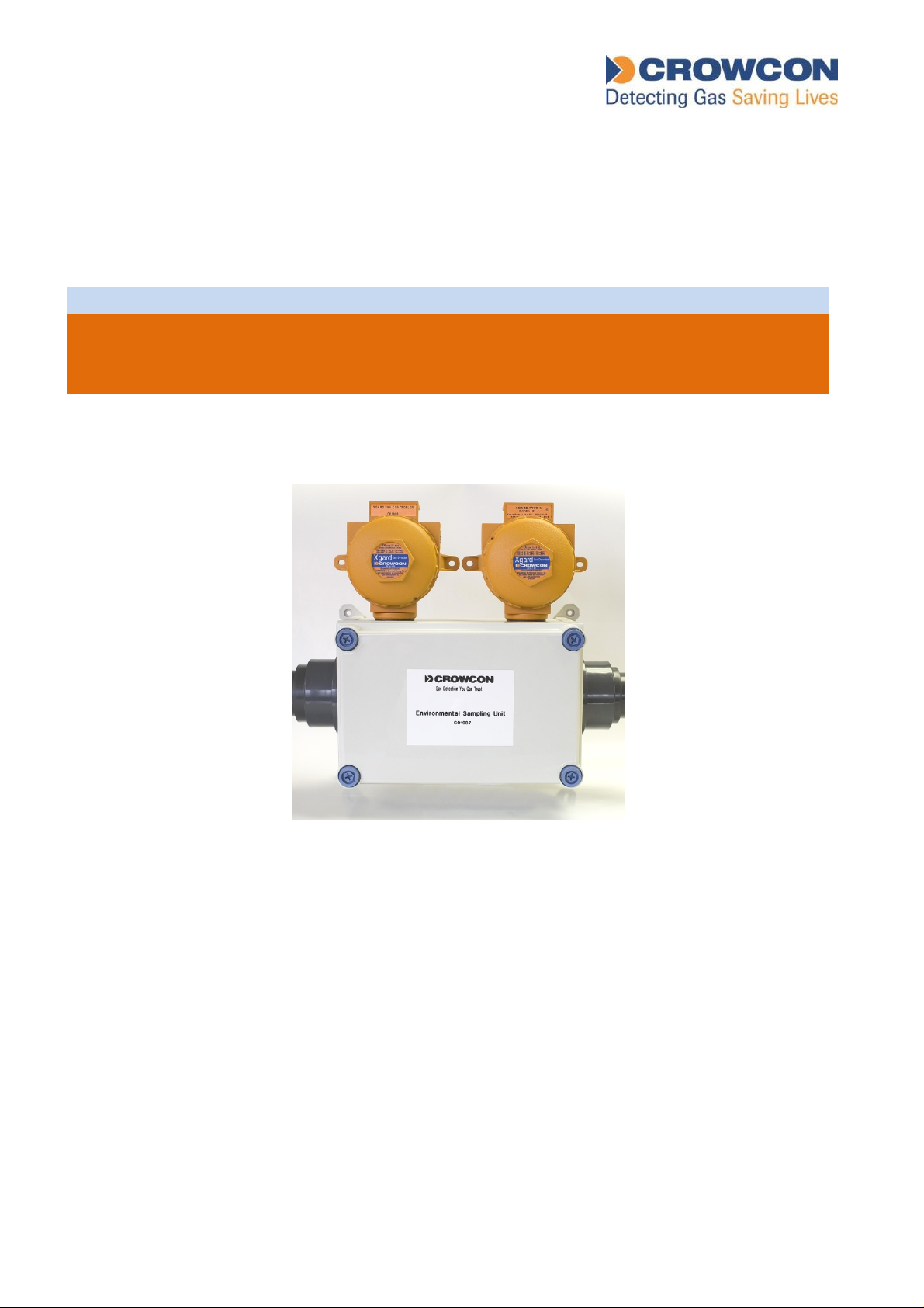
Xgard ESU
Environmental Sampling Unit
Installation, Operation and Maintenance Instructions
Issue 5
January 2015
Page 2

TABLE OF CONTENTS
1. INTRODUCTION .................................................................................................................................. 2
2. INSTALLATION ................................................................................................................................... 2
3. COMISSIONING CHECKS................................................................................................................... 4
4. MAINTENANCE................................................................................................................................... 4
5. SPARE PARTS.................................................................................................................................... 5
6. SPECIFICATIONS ............................................................................................................................... 6
7. APPENDIX A – ESU GENERAL ARRANGEMENT .............................................................................. 7
8. APPENDIX B – INSTALLATION OPTIONS ......................................................................................... 8
9. APPENDIX C – VORTEX CONFIGURATION INSTRUCTIONS ............................................................ 9
10. WARRANTY ...................................................................................................................................11
ESU Installation, Operating and Maintenance Instructions 1
Page 3

1. INTRODUCTION
The ESU Environmental Sampling Unit is designed to make it easier to monitor gases such as
chlorine and sulphur dioxide which, because they have a high density and are readily absorbed
into many materials, are difficult to detect using conventional point detectors. The explosion proof
version may be used for monitoring heavy flammable gases such as LPG. The ESU uses a
sampling chamber technique in which gas is sampled using an electric fan. This is installed in the
outlet from the chamber and thus draws samples through the system via pipe-work connected to
the chamber.
The ESU fan and gas detector must be connected to a Crowcon Gasmaster or Vortex control
panel, which will monitor the fan to ensure a sample is being drawn and display the gas level and
activate alarms. Wiring diagrams are shown on page 2 of this manual.
The sampling chamber is made from high impact ABS, and houses a gas detector with its junction
box on the outside. Connection points for the electrical supply to the fan are also made externally
to the sampling chamber via a second junction box.
2. INSTALLATION
One or two Xgard gas detectors can be fitted to the ESU. Refer to the General Arrangement
diagram on page 5 for details of how to fit the detector. A second detector (if used) is mounted at
the bottom of the enclosure.
The standard arrangement is for the sampling chamber to be fitted with 3 metres of PVC pipe on
either side of a T piece at the gas entry point to the chamber. It is possible to extend this to 6
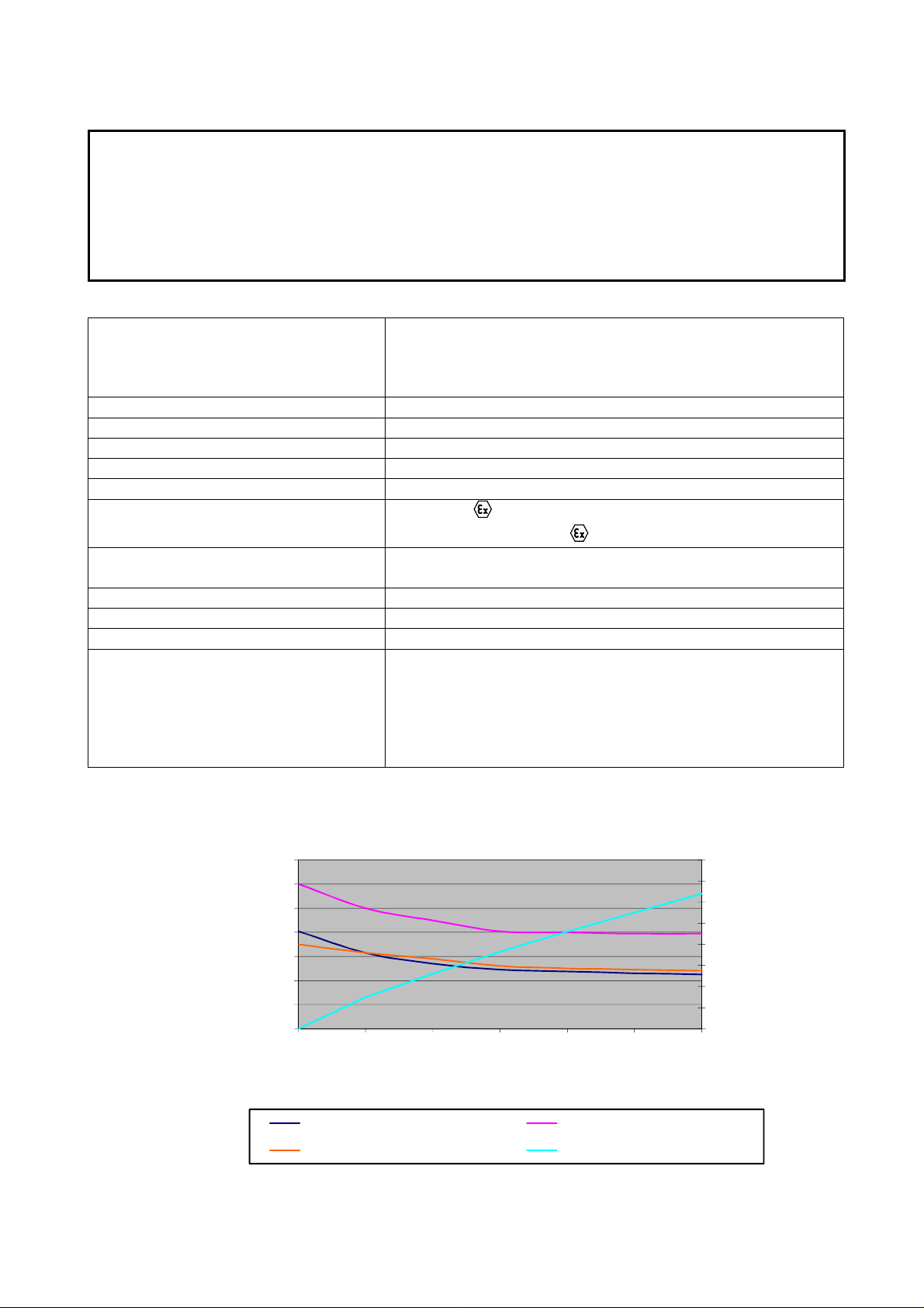
metres, or to put the chamber at one end of a 12 metre length of sampling pipe. The attached chart
shows that with 12 metres of straight pipe, the minimum flow rate is 0.4 metres/sec which ensures
detector response in 60 seconds at most (including the T90 response time of the sensor). Any
extra bends or T pieces count as 2 metres of pipe. Other options are available, for example the
pipe-work can be closed at both ends with a series of small inlet holes along its length, or it can be
mounted vertically with a series of sampling holes along its length but with the bottom open for
immersing in liquid of varying depth. The sampling chamber should always be mounted above the
surface of any liquids to avoid ingress of water.
Because of the very low pressure developed by the unit, care must be taken with siting pipes to
ensure that extraneous pressure effects are eliminated, particularly in regard to wind and thermal
currents with open-ended pipes.
For wet well installations Crowcon recommend that holes are drilled every 500 mm (19.7”) in a
vertical plane from the bottom of the open-ended pipe. To ensure that airflow is always drawn from
the lowest level when the end of the pipe is submerged, the holes should be larger at the bottom,
gradually reducing in diameter towards the top of the pipe. As a general rule, the lowest hole
should be 6mm (1/4”) in diameter, reducing by 1mm (1/25”) per hole towards the top of the pipe.
These figures are dependent on the total length of the pipe, and should be adjusted as necessary.
ESU Installation, Operating and Maintenance Instructions 2
Page 4
If the gas to be monitored is potentially explosive, for example heavy hydrocarbon gases which can
accumulate in drains, the version certified for use in a hazardous area must be used.
It is important to note the conditions for connecting and use of the ESU to ensure compliance with
the hazardous area certification.
a. Electrical supply to the fan must be fused at the power supply at 250 mA (fuse to have a
breaking a capacity of 4000A). This fuse is fitted to the fan supply PCB fitted within the fan
junction box.
b. Electrical supply to the fan junction box must be via cable suitable for hazardous areas,
such as steel
wire armoured type 6942X terminated via an Exd gland at the junction box.
c. The sampling chamber must be mounted so as to be protected from receiving any direct
impact.
d Detecting head to be cabled in accordance with instructions in the Xgard Installation,
Operating and Instruction Manual.
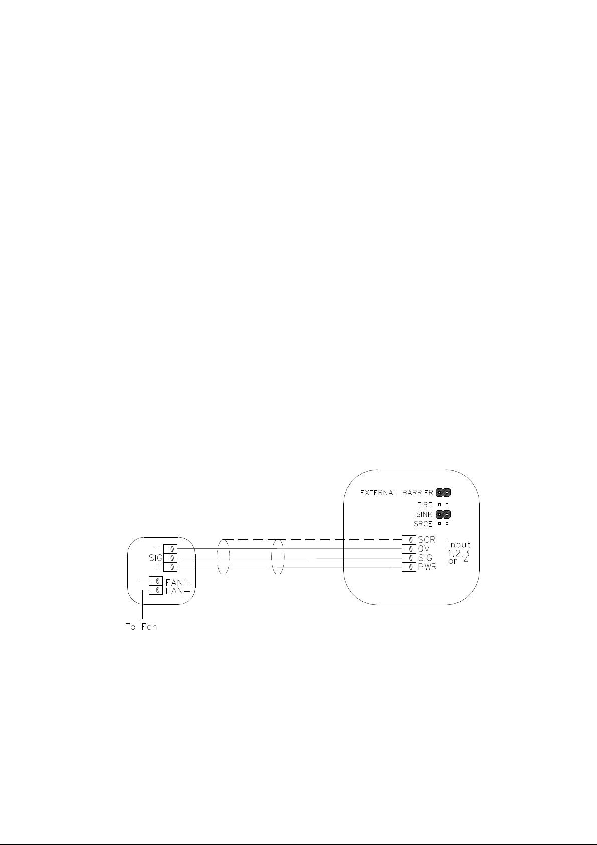
Connect the ESU fan controller to the Gasmaster control panel as shown. The Gasmaster input
channel ‘Type’ should be configured as ‘ESU’. Alarm levels for the ESU input channel should be
set to:
Alarm 1 On threshold (fan stalled): 10 (rising alarm, non-latching)
Alarm 1 Off threshold: 9.5
Alarm 2 threshold (fan open-circuit): 5 (falling alarm, non-latching)
Refer to the Gasmaster Installation, Operation and Maintenance Manual for more details on how to
configure the input channel.
Channel Link Settings
Fan Controller Junction Box
Gasmaster
ESU Installation, Operating and Maintenance Instructions 3
Page 5
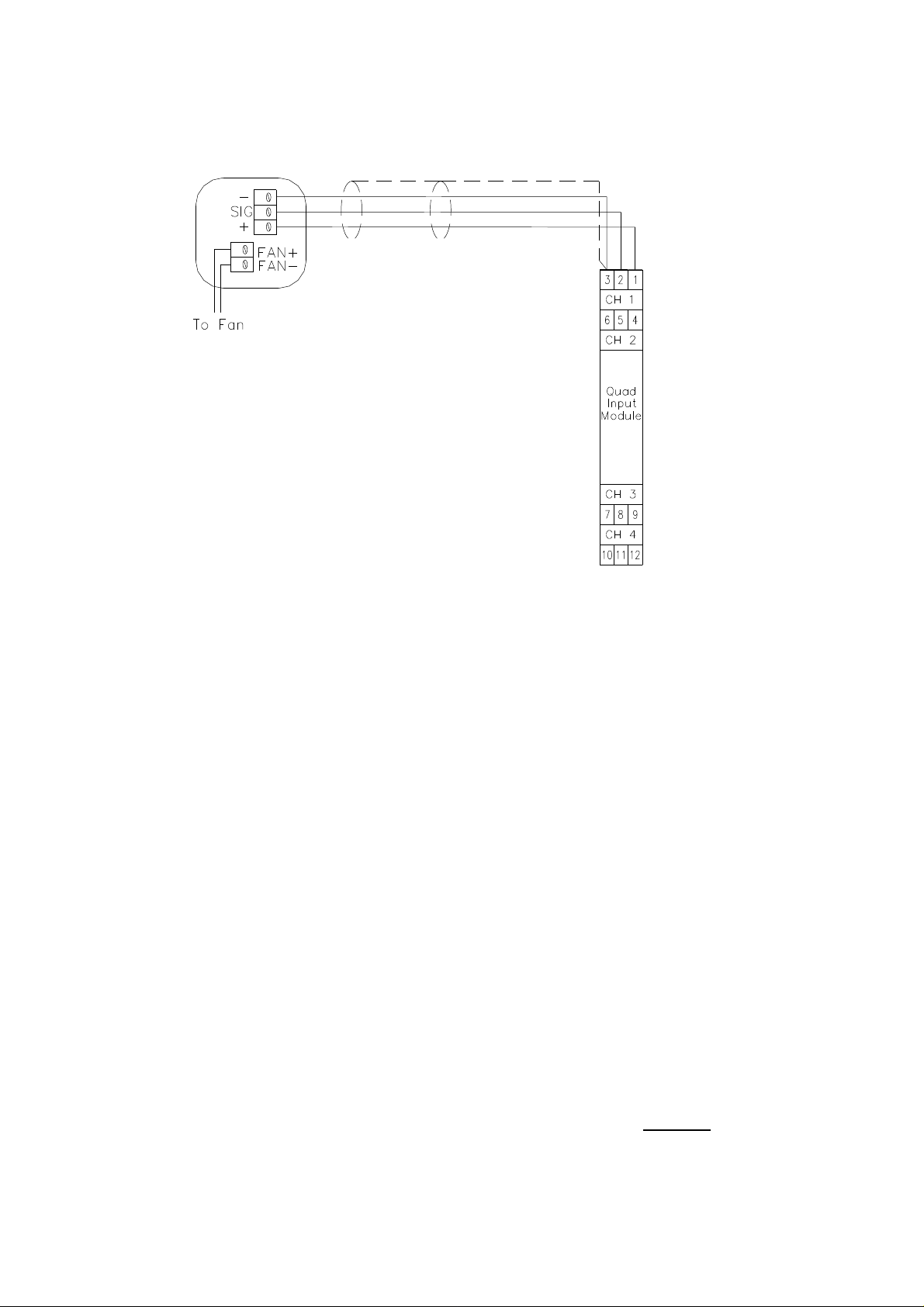
Connect the ESU fan controller to the Vortex control panel as shown. Refer to the Appendix C of
this manual for details on how to configure the input channel.
Fan Controller Junction Box
Vortex
Input Channel
1,2,3 or 4
Set module input
switch to SINK
3. COMISSIONING CHECKS
The gas detectors(s) should be zeroed and calibrated in accordance with their installation
instructions provided.
After installation it is recommended that a flow check is carried out. This can be done simply by
holding a strand of wool or cotton by one end across each entry hole on the sample pipe and
check that the strand is drawn towards the hole by the air-flow.
4. MAINTENANCE
The ESU should be inspected regularly to check that the fan or pipes are not becoming blocked, or
that water has entered the sampling chamber. The gas detector(s) should be tested and calibrated
by applying test gas directly to the sensor in accordance with their operating instructions.
In the unlikely event that the fan fails, the Gasmaster or Vortex system to which the ESU is
connected will produce a fault signal. To identify and correct the fault follow the following:
1. Check that the fan has not become blocked and prevented from rotating, remove any
obstructions.
2. Ensure there is no flammable gas present (obtain a hot work permit if necessary), un-screw
the fan junction box lid and remove and test the fan supply fuse, replace if necessary.
3. If the fuse is OK and the fan is not blocked it is likely that the fan has failed. Replace the fan
only with the correct part supplied by Crowcon. Alternative fans must not be used. When
replacing fans on certified ESU’s, it is essential that the fan cable gland is screwed securely
into the fan junction box, and retained using Loctite 222 thread locking compound.
ESU Installation, Operating and Maintenance Instructions 4
Page 6

5. SPARE PARTS
E01736 Uncertified fan assembly (safe area units only)
S011856 ‘Exm’ certified fan assembly (hazardous area units)
S011857/2 Fan controller PCB
E01307 Fuse 250mA HRC 20mm for fan
M04873 Xgard sensor retainer adaptor
M04874 Xgard retainer washer
M04876 Interface gasket
M04092 ESU cover screw
Refer to the Xgard Installation, Operating and Maintenance Instructions for gas detector spare
parts information.
ESU Installation, Operating and Maintenance Instructions 5
Page 7
6. SPECIFICATIONS
Important Notice:
and a portable gas detector should be worn by any personnel entering the area.
024681012
ESU is designed for rapid detection of significant releases of dense toxic gases such as chlorine,
or a build-up of flammable vapours. The operating principle of the ESU results in a diluted gas
sample being introduced to the gas detector(s), and therefore the gas level indicated by the
sensor will be lower than the actual gas levels present at the release source. Ventilation
procedures should always be carried out prior to entering an area where a release has occurred;
ESU Part Numbers Hazardous area certified ESU: C01987 (for one sensor)
C011029 (for two sensors)
Non certified ESU (safe area): C011004 (for one sensor)
C011031 (for two sensors)
Dimensions 397 (w) x 363 (h) x 180 (d) mm (15.3 x 10.6 x 7 ins)
Material Polycarbonate
Fan Power 3W (Watts)
Supply Voltage (Fan) 24v DC nominal from Gasmaster
Operating Temperature
Approval Code (certified type only)
-10 to +50ºC (14 to 104ºF)
Fan: ATEX II 2 G Ex m IIC T4
Fan junction box: ATEX II 2 G Ex d IIC T6
Certificate Number Fan: Baseefa 03 ATEX 0033X
Fan junction box: Baseefa 04 ATEX 0024X
Piping 60mm Diameter PVC (2” pipe)
Maximum Pipe Length 12 Metres (36’)
Weight (excluding piping) 3.5kg (7.7 lbs) excluding gas detector
Accessories The ESU is supplied with a set of fittings comprising:
Retaining nut, washer and gasket for mounting the Xgard
detector(s).
2 elbows, 2 end caps, 1 T-piece, 2 reducing bushes and 4
pipe clamps. 2” pipe is available separately in 2 metre
lengths.
Typical Air Flow Rates
Flow Rate (m/sec)
1.4
1.2
1
0.8
0.6
0.4
0.2
0
Sample Pipe Length (metres)
Horizontal Vertical - downward flowing
Vertical - upward flowing Average response time
ESU Flow Rates
8
7
6
5
4
3
2
Sample Time (sec)
1
0
ESU Installation, Operating and Maintenance Instructions 6
Page 8
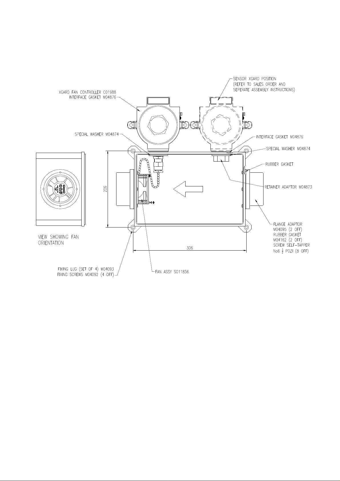
7. APPENDIX A – ESU GENERAL ARRANGEMENT
AIR FLOW
ESU Installation, Operating and Maintenance Instructions 7
Page 9
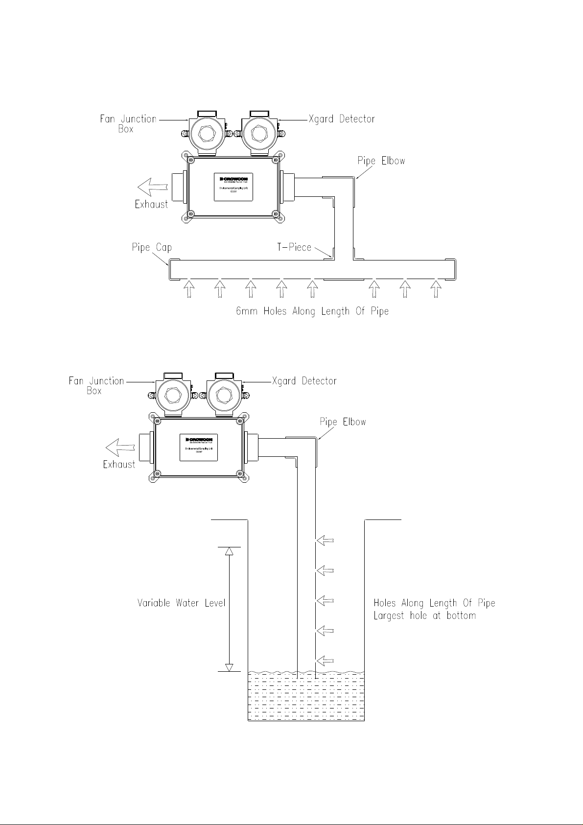
8. APPENDIX B – INSTALLATION OPTIONS
For monitoring along a horizontal surface:
For monitoring a wet-well:
ESU Installation, Operating and Maintenance Instructions 8
Page 10
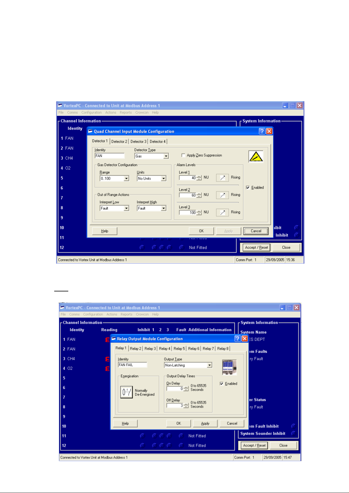
9. APPENDIX C – VORTEX CONFIGURATION INSTRUCTIONS
Once the ESU fan has been connected to the relevant Vortex input channel as described in
Section 2, the Vortex control panel must be configured to provide the fan monitoring function. The
following instructions describe configuration using the Vortex PC software supplied with the Vortex
panel. Set all parameters as shown. The gas detector(s) fitted to the ESU should be connected as
shown in the Vortex Manual.
a) Input channel configuration
b) Fault (‘Fan Stopped or Disconnected’) relay configuration: the selected Fault relay
must be set with a 3 second off delay. Level 1 and Level 2 ‘Fan Slow’ and ‘Fan Stalling’
alarms can be set as latching or non-latching as required.
ESU Installation, Operating and Maintenance Instructions 9
Page 11
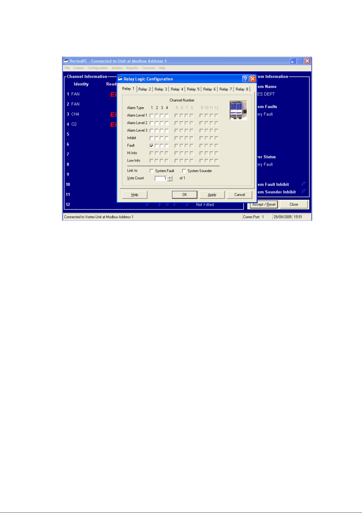
c) Fault relay logic configuration
With the fan running normally the channel display should read 20-30. To test that the Vortex relay
outputs operate correctly open the ESU and carefully slow the fan by resting a finger on the innerhub, the Vortex display should rise above 40 at which point the Level 1 Fan Slow relay should
activate. Apply more pressure to the hub and watch for the display to rise above 60, at which point
the Level 2 Fan Stalling relay should activate. Finally, completely stop the fan and check that the
display reads E006 fault, and the Fault relay activates.
Fan alarms: Alarm 1 (fan slow), Alarm 2 (fan stalling) and Fault (fan stalled), can either be
assigned to individual relays or grouped to a common relay.
ESU Installation, Operating and Maintenance Instructions 10
Page 12

10. WARRANTY
Warranty Statement
This equipment leaves our works fully tested and calibrated. If within the warranty period of 1 year,
the equipment is proved to be defective by reason of faulty workmanship or material, we undertake
at our discretion either to repair or replace it free of charge, subject to the conditions below.
Warranty Procedure
To facilitate efficient processing of any claim, contact our customer support team on 01235 557711
with the following information:
Your contact name, phone number, fax number and email address.
Description and quantity of goods being returned, including any accessories.
Instrument serial number(s).
Reason for return.
Obtain a Returns form for identification and traceability purpose. This form may be downloaded
from our website ‘crowconsupport.com’, along with a returns label, alternatively we can ‘email’ you
a copy.
Instruments will not be accepted for warranty without a Crowcon Returns Number (“CRN”).
It is essential that the address label is securely attached to the outer packaging of the
returned goods.
Units returned to Crowcon as faulty and are subsequently found to be ‘fault free’ or requiring
service, may be subject to a handling and carriage charge.
Warranty Disclaimer
The guarantee will be rendered invalid if the instrument is found to have been altered, modified,
dismantled, or tampered with. Any service by 3rd parties not authorized & certified by Crowcon will
invalidate the warranty on the equipment. Use of alternative manufacturer’s sensors which have
not been approved by Crowcon will invalidate the warranty of the product as a whole. The warranty
does not cover misuse or abuse of the unit.
Repair Warranty
Product repairs within the warranty period will be free of charge for both labour and parts. Should a
full service / calibration also be due, then this is agreed with the customer to be carried out at the
same time as the repair and the service element will be chargeable.
Replaced parts (outside of product warranty) will usually carry a further 12 month warranty (sensor
warranty exclusions are published on the Crowcon Intranet), Repairs / Service labour carries a 3
month warranty. Should a second but unrelated failure occur outside of the product warranty or
parts warranty where applicable, this will be subject to separate charges.
Crowcon accept no liability for consequential or indirect loss or damage howsoever arising
(including any loss or damage arising out of the use of the instrument) and all liability in respect of
any third party is expressly excluded.
The warranty and guarantee does not cover the accuracy of the calibration of the unit or the
cosmetic finish of the product. The unit must be maintained in accordance with the Operating and
Maintenance Instructions.
Our liability in respect of defective equipment shall be limited to the obligations set out in the
guarantee and any extended warranty, condition or statement, express or implied statutory or
ESU Installation, Operating and Maintenance Instructions 11
Page 13

otherwise as to the merchantable quality of our equipment or its fitness for any particular purpose
UK Office
USA Office
European Office
Singapore Office
China Office
is excluded except as prohibited by statute. This guarantee shall not affect a customer’s statutory
rights.
For warranty and technical support enquiries please contact:
Customer Support
Tel +44 (0) 1235 557711
Fax +44 (0) 1235 557722
Email: [email protected]
© Crowcon Detection Instruments Ltd 2015
Crowcon Detection Instruments
Ltd
172 Brook Drive,
Milton Park,
Abingdon
Oxfordshire OX14 4SD
Tel: +44 (0)1235 557700
Fax :+44 (0)1235 557749
Email: [email protected]
Website: www.crowcon.com
Crowcon Detection
Instruments Ltd
1455 Jamike Ave, Suite 100
Erlanger
Kentucky 41018
Tel: +1 859 957 1039 or
1 800 527 6926
Fax: +1 859 957 1044
Email: [email protected]
Website: www.crowcon.com
Crowcon Detection Instruments Ltd
Vlambloem 129
3068JG
Rotterdam
Netherlands
Tel: +31 10 421 1232
Fax: +31 10 421 0542
Email: [email protected]
Website: www.crowcon.com
Crowcon Detection
Instruments Ltd
Block 194 Pandan Loop
~06-20 Pantech Industrial Complex
Singapore 128383
Tel: +65 6745 2936
Fax: +65 6745 0467
Email: [email protected]
Website: www.crowcon.com
Crowcon reserves the right to change the design or specification of this product without notice.
Crowcon Detection Instruments Ltd
(Beijing)
Unit 316, Area 1, Tower B, Chuangxin
Building
12 Hongda North Road, Beijing
Economic Technological Development
Area
Beijing, China 100176
Tel: +86 10 6787 0335
Fax: +86 10 6787 4879
Email: [email protected]
Website: www.crowcon.com
ESU Installation, Operating and Maintenance Instructions 12
 Loading...