

Page 1
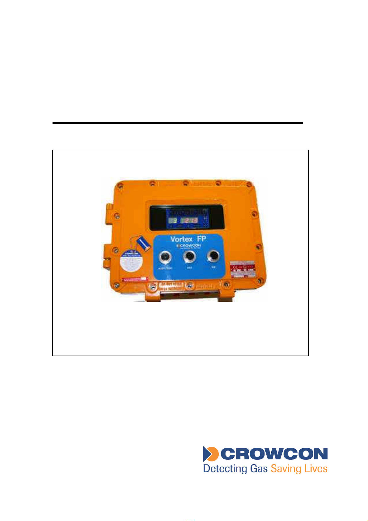
Vortex FP Compact
Flameproof Gas Detection Control System
Installation and Operation Manual
Issue 1
January 2013
Page 2

INTRODU CTION
The Crowcon Vortex FP Compact gas detection control system can be installed in Zone 1 or
Zone 2 hazardous areas, and is designed to monitor toxic and/or flammable gas detectors,
or fire detection devices. The system must be installed and operated in accordance with
these instructions.
WARNING
The equipment described in this instruction manual has mains
voltages applied to it. Ensure correct safety procedures are adopted
before working on the equipment.
The equipment described in this manual is designed for detection of
flammable and/or toxic gases. Ensure local safety procedures are
adopted before carrying out any maintenance or calibration work.
The equipment described in this manual may be connected to remote
alarms and/or shutdown systems. Ensure that local operating
procedures are adopted before carrying out any maintenance or
calibration work.
© Crowcon Detection Instruments Ltd 2013
Vortex FP Compact Installation & Operation Manual 1
Issue 1, January 2013
Page 3

TABL E OF CONTEN TS
1. INTRODUCTION......................................................................................................................... 3
1.1 SAFETY INFORMATION ...................................................................................................................3
1.2 PRODUCT DESCRIPTION................................................................................................................. 3
2. INSTALLATION .......................................................................................................................... 4
3. OPERATION & MAINTENANCE................................................................................................ 6
3.1 APPLYING POWER ......................................................................................................................... 6
3.2 COMMISSIONING............................................................................................................................ 7
3.3 ROUTINE MAINTENANCE ................................................................................................................7
3.4 VORTEX FP COMPACT DISPLAY AND CONTROLS............................................................................. 8
4. TECHNICAL SPECIFICATION.................................................................................................11
5. WARRANTY STATEMENT ...................................................................................................... 12
Vortex FP Compact Installation & Operation Manual 2
Issue 1, January 2013
Page 4

1. INTRODUCTION
1.1 SAFETY INFORMATION
Vortex FP Compact is a certified Flameproof (Exd) detector suitable for use in ATEX Zone 1
or Zone 2 hazardous areas.
Vortex FP Compact must be installed, operated and maintained in strict accordance
with these instructions, warnings, label information, and within the limitations stated.
The cover retaining bolts must be kept tightly closed until power to the control system
is isolated - otherwise ignition of a flammable atmosphere can occur.
Before removing the cover for maintenance or calibration purposes, ensure the
surrounding atmosphere is free of flammable gases or vapours.
Maintenance and calibration operations must only be performed by qualified service
personnel.
Only genuine Crowcon r eplacement parts must be used; substitute components may
invalidate the certification and warranty of the system.
Vortex FP Compact must be protected from extreme vibration.
Vortex FP Compact must be protected from direct sunlight in hot environments as
this may cause the temperature of the system to rise above its specified limits and
cause premature failure.
Vortex FP Compact is supplied certified for use in hazardous areas only with the
components originally fitted. No other devices may be fitted within the Vortex FP
Compact enclosure.
1.2 PRODUCT DESCRIPTION
Vortex FP Compact is a sophisticated control system designed for monitoring up to twelve
gas detectors. Three input channels may alternatively be used for monitoring conventional
smoke or heat detectors, or flame detectors. Vortex FP Compact may contain (depending on
specification) up to 16 relays for control of external devices.
Vortex FP Compact is supplied in an Exd Flameproof junct ion box constructed of LM25
aluminium and finished with a tough polyester coating. Gas levels, alarms and faults can be
viewed through the window, and system functions can be accessed either via the pushbuttons or by using the supplied ‘Crowmag’ magnetic key.
Vortex FP Compact may be delivered configured for 1-4, 1-8 or 1-12 input channels, and
with up to two 8-way relay modules (one relay module only if three input modules are fitted).
If intrinsically safe (I.S.) field devices are to be connected, the required Zener barriers or
galvanic isolators must be located within a separate Exd certified enclosure. Alternatively a
larger version of the product: Vortex FP is available with space sufficient for such devices.
Please refer to the specification sheet provided with the system for exact configuration
details.
Vortex FP Compact is based on Crowcon’s Vortex control system, and the standard Vortex
manual (part number M07211) must be referred to in conjunction with these instructions.
Vortex FP Compact is not available with back-up batteries fitted. For continued operation in
the event of mains supply failure, it is recommended that Vortex FP Compact is connected to
a suitable UPS system.
A view of internal system modules and components is shown on the following page.
Vortex FP Compact Installation & Operation Manual 3
Issue 1, January 2013
Page 5
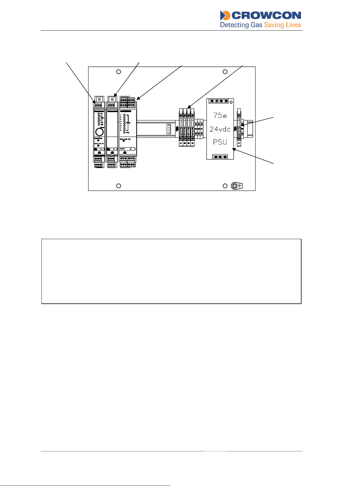
Warning
Terminals
Node Controller Module Quad Input
Module(s)
Module(s)
Terminals Modules
Supply Unit
Figure 1 – System Base-Plate View
Relay Output
DC Power Distribution
AC mains
Power
2. INSTALLATION
This product is designed for use in Zone 1, Zone 2 hazardous areas, and is certified
ATEX Ex d IIB+H2.
Installation must be in accordance with the stipulations made on the ATEX certificate,
and the recognised standards of the appropriate authority in the country concerned.
For further information please contact Crowcon. Prior to carrying out any installation work
ensure local regulations and site procedures are followed.
General Notes:
Vortex FP Compact weighs approximately 37.5Kg. Appropriate lifting equipment must be
used when transporting and mounting the system.The surface to which the system will be
mounted, and the fixings used must be able to support its weight adequately.
Care should be taken so as to avoid damage the painted finish of the system.
Vortex FP Compact has an ingress protection rating of IP66 and is therefore suitable for
outdoor installation. It is recommended however that a suitable sun-shade and rain canopy
is fitted.
Cabling must be in accordance with the recognised standards of the appropriate authority in
the country concerned and meet the electrical requirements of the field devices.
Field cables must be connected to the system using ATEX certified Exd cable glands, which
are suitable for the type of cable used. Crowcon recommends Steel Wire Armoured (SWA)
Vortex FP Compact Installation & Operation Manual 4
Issue 1, January 2013
Page 6

cable. Other cables types may be used provided suitably certified cable glands are also
used.
Important note: If a Vortex FP Compact system is to be connected to a control system in a
safe area (ie control room, plant room etc) it is strongly recommended that the Vortex RS485 function terminals are connected to an accessible point in the safe area. All Vortex
configurations, calibration and diagnostic functions can then be carried-out using the Vortex
PC software supplied with the system from the safe area without requiring the Flameproof
junction box to be opened. Refer to the Vortex manual for more details.
1. The fixing brackets/bolts are supplied with, but not fitted to the Vortex FP Compact
enclosure. To fit the brackets lay the Vortex FP Compact enclosure on a suitable
surface and raise onto one end. Remove the lid retaining bolts and carefully open the
lid of the enclosure. The fixing brackets should be secured to the enclosure using the
supplied retaining bolts/nuts.
Once the brackets are attached, close the door and restrain using one fixing bolt
before attempting to mount the cabinet.
2. Lift the system in to place and secure via the mounting bracket fixing points shown in
the diagram on the next page.
3. Ten M20 entries are provided for field cables. Connect the cables to the system
using certified Exd cable glands. Certified M20 plugs are fitted to five entries and can
be removed if necessary for additional cables. All spare cable entries must have Exd
certified plugs securely fitted.
4. Cable conductors should be connected to the Vortex modules and terminals as
shown in the Vortex manual (M07211). Warning: power must not be applied until
the enclosure lid has been closed and securely tightened.
5. I.S. field devices (gas detectors and/or alarms) must be connected via safety barriers
mounted externally from the system, in accordance with their instructions. Zener
Barriers must be grounded to a dedicated I.S. earth.
6. Once all cable connections have been m ade the lid should be closed and tightly
secured using the fixing bolts.
7. Connections to field devices (gas detectors, fire detectors etc) must be made
according to the instructions pr ovided with each device.
System dimensions are shown on the following page.
Vortex FP Compact Installation & Operation Manual 5
Issue 1, January 2013
Page 7
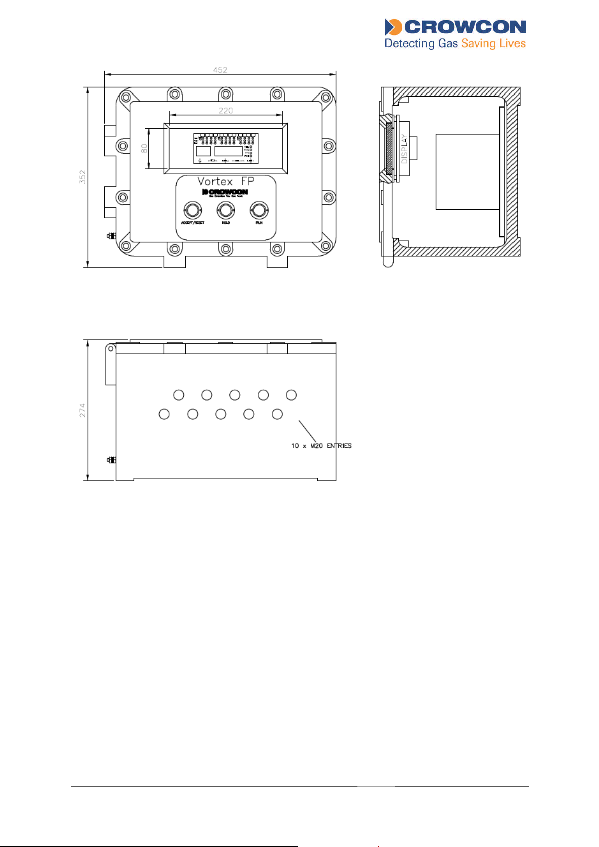
Figure 2 – System Dimensions
3. OPERATION & MAINTENANCE
3.1 APPLYIN G POWER
Before applying power ensure that any control or shutdown systems to which the
Vortex FP Compact is connected are inhibited.
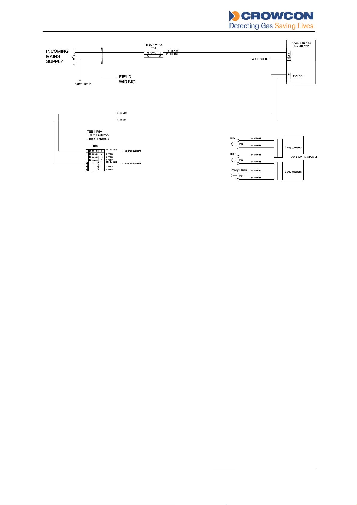
AC power supply cables must be connected to the AC terminals shown in Figure 1, with the
Live conductor connected to t he fused terminal. A wiring diagram is shown on the next page.
If the equipment is permanently connected to a mains supply then a dedicated circuit
breaker must be included in the installation, to comply with EN 61010-1. The circuit breaker
must be easily accessible, must be marked as the disconnecting device for the Vortex FP
Compact system, and the ON and OFF positions must be clearly marked.
The circuit breaker must comply with the relevant requirements of IEC60947-1 and
IEC60947-3. The protective earth must not be disconnected even when the breaker is
activated.
Vortex FP Compact Installation & Operation Manual 6
Issue 1, January 2013
Page 8
Once all field cables have been installed, apply power to system from either the 110/230Vac
or 24 V dc external supplies.
When power is applied the green Power Healthy LED will illuminate to indicate that the
system is operational.
If after a settling period faults are reported, check the sensor connections again or refer to
Faults table in section 6.4 of the Vortex manual.
Vortex FP Compact should display readings for all channels/sensors being monitored. Allow
sensors to settle before commencing calibration; refer to sensor instructions supplied with
detectors for recommended settling times.
3.2 COMMISSIONING
Crowcon strongly recommends that fixed gas detecting installations are fully commissioned
as soon as possible after installation. Commissioning should include a full check of cabling
and equipment functions, as well as output functions. Gas detectors must be calibrated, and
the function of all gas and fire detectors must be verified in accordance with their
instructions.
3.3 ROUTINE MAINTENANCE
Crowcon recommends that gas detectors are tested routinely to ensure correct calibration
and operation. Gas detectors, sensors may require recalibration at least every 6 months.
Fire detectors should be tested every 3 to 6 months. Site procedures may require more
frequent testing.
For detailed instructions on the routine functional testing of detectors, please refer t o the
relevant Installation, Operating and Maintenance Instructions provided with each detector.
Output functions such as audible/visual alarm operation and signalling to external equipment
should be tested and verified on a regular basis.
Vortex FP Compact Installation & Operation Manual 7
Issue 1, January 2013
Page 9
Vortex FP Compact requires cleaning as necessary to ensure the display window does not
become obscured. The enclosure, cables and glands should also be checked periodically to
ensure that Flameproof integrity is maintained.
For more detailed information on Vortex system maintenance, please refer to Section 7 of
the standard Vortex manual (part number M07211).
It may be necessary to open or remove the lid of the Vortex FP Compact enclosure in order
to perform some maintenance functions. Vortex FP Compact must be completely de-
energised before the lid is opened; local procedures must be adhered to when
servicing equipment installed in a hazardous area.
3.4 VORTEX FP COMPACT DISPLAY AND CONTROLS
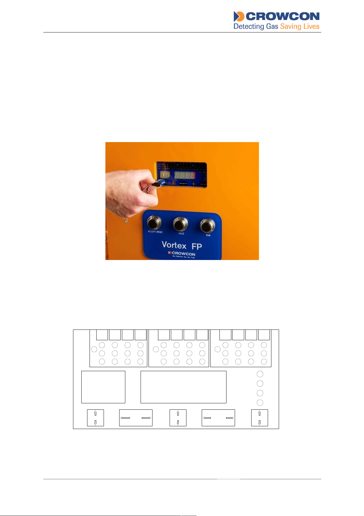
Vortex FP Compact incorporates a Display Module which provides a display of detector
signals and reports the current status of the system. Display functions are controlled using a
Crowmag calibration tool, which should be oriented (horizontally or vertically) as indicated by
the arrows on the display function fields.
Alarm 2
InhA
Alarm 1
Fault
1
234 5
Channel Reading
Step
Lamp
Test
InhB
678 9
Inhibit A Inhibit CInhibit B
InhC
10 11 12
%LEL
%VOL
PPM
FIRE
Power
Channel
Test
System
Fault
Hold
Figure 3 – Display Module Layout
Vortex FP Compact Installation & Operation Manual 8
Issue 1, January 2013
Page 10
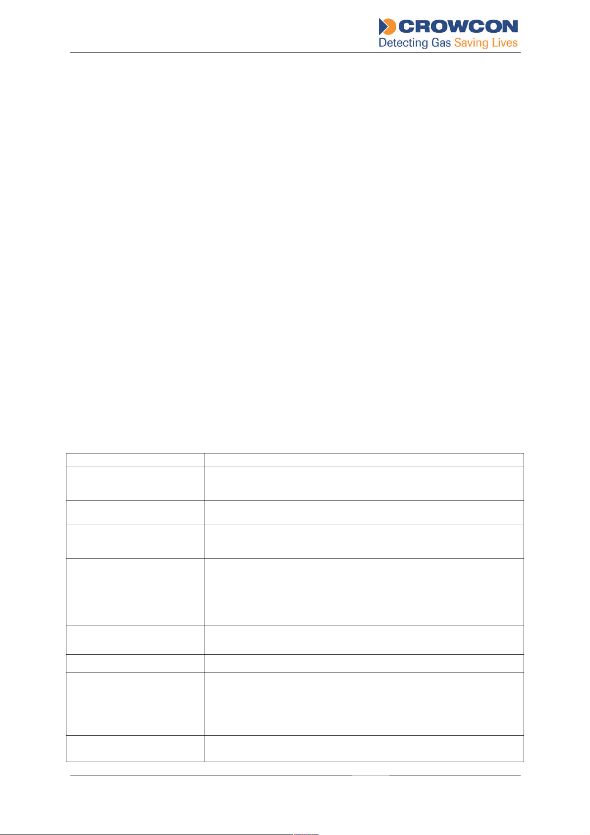
Crowmag control functions:
Feature
Description
Step: when the system is holding on a particular channel (ie the ‘Hold’ button has
been pressed), use the Step function to display and hold the next channel in
sequence. Also used to increase the Reading display in Channel Test mode
(section 7.4 of the standard Vortex manual). Hold Crowmag vertically to
activate.
Lamp test: lights all display LED’s. Hold Crowmag horizontally to activate.
Inhibit: places the appropriate input module into inhibit state. An LED indicates when
an input module is inhibited (‘Inh A’, ‘Inh B’, ‘Inh C’ LED’s). Hold Crowmag
vertically for input modules A and C, horizontally for input module B.
Warning: placing the system into inhibit state will isolate all output
functions: output/warning functions will therefore not operate in the
event of a gas or fire alarm. Care must be taken when using the inhibit
function to ensure the system does not remain permanently inhibited.
The system must be taken out of inhibit state once maintenance actions
have been performed.
Button functions:
Accept/Reset: silences the internal sounder and resets latched relays once an alarm state
has been cleared.
Hold: forces the display to ‘Hold’ on a particular input channel. Also used to
decrease the Reading display in Channel Test mode (see Vortex manual
section7.4).
Run: press either to restart cycling through the channels after HOLD has been
selected, or to end Channel Test mode.
Other display indications and functions are described below:
System Fault LED Yellow LED indicates a system fault. Specific system faults are
indicated on the Node controller module; refer to the Vortex manual
for more information.
Power Healthy LED Yellow LED indicates system power status. Refer to section 6.4.2 of
the Vortex manual for more information.
Zone Inhibit LED’s Yellow LED for each zone (A,B,C: Quad Input Modules). Indicates
that the zone (quad input module), or a channel in the zone, is
currently inhibited.
Hold LED Green LED when continuously illuminated indicates that the HOLD
button has been used to hold the current channel.
When this LED flashes, it indicates "Jump on Alarm". The Channel
Reading now shows the channel (or the first of more than one
channel) that has gone into alarm.
Channel Test LED Yellow LED when flashing indicates that the system is in Channel
Test mode. Refer to section 7.4 of the standard Vortex manual.
Units Indication LEDs Indicates the units for the currently displayed channel.
Reading The reading on the input device (detector) currently indicated by the
Channel display. The number is shown in red on a 7-segment display.
This should be read in conjunction with the 'units' indication. For the
use of this display in Channel Test mode, see section 7.4 of the
standard Vortex manual.
Channel Number Green 7-segment display that normally displays the number of the
currently-displayed channel (detector). For the use of this display in
Vortex FP Compact Installation & Operation Manual 9
Issue 1, January 2013
Page 11
Channel Test mode, see section 7.4 of the standard Vortex manual.
Feature
Description
Channel Alarm 1 and Alarm
2 LEDs
Red LEDs for each channel. Illuminated when the alarm level is
reached on the channel. When the alarm is first raised, the LED
flashes. After the ACCEPT/RESET button is pressed, the LED goes
out if the alarm condition has been cleared. If the alarm condition still
exists, it displays continuously.
Channel Fault LEDs Yellow LED for each channel. Illuminated when a fault is detected on
the channel. When the fault is first raised, the LED flashes. After the
ACCEPT/RESET button is pressed, the L ED goes out if the fault has
been cleared. If the fault still exists, it displays continuously.
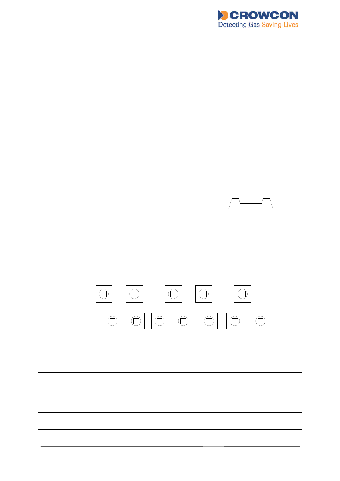
Additional functions are available via buttons fitted to the rear of the display PCB. The button
locations and functions are shown below.
Warning: access requires the Vortex FP Compact enclosure to be opened; site
procedures must be strictly adhered to before attempting to open the enclosure or to
operate a powered system with an open enclosure. Performing any of the following
functions will normally require a ‘hot-work permit’ to be issued by the site supervisor,
and the local area must be tested to ensure no flammable gases or vapours are
present.
RIBBON CABLE CONNECTOR
STEPLAMP TESTINHIB1INHIB2INHIB3
ACCEPT/R ERUNHOLDZEROCALPEAKHOLDCH TEST
Figure 4 – Rear of Display Module
HOLD Button Press to hold the display on the current channel.
CHANNEL TEST Button After the HOLD button has been used to select a channel, use the
Channel Test button to display alarm levels or for zero adjustment and
calibration. Refer to the standard Vortex manual for more information.
This button can be disabled using Vortex PC.
PEAK HOLD CAL Button Used for the Peak Hold Calibration, refer to section 7.3 of the
standard Vortex manual. Can be disabled using Vortex PC.
Vortex FP Compact Installation & Operation Manual 10
Issue 1, January 2013
Page 12

CAL Button Used for the Calibration, refer to sections 3.8 and 7 .3 of the standard
Vortex manual. Can be disabled using Vortex PC.
ZERO Button Used for the Zero Adjustment refer to sections 3.8 and 7.3 of the
standard Vortex manual. Can be disabled using Vortex PC.
ZONE INHIBIT Buttons One button for each zone (Quad Input Module). Used to prevent the
corresponding output relays from being activated during testing or
calibration. Refer to sections 3.8, 7.3 and 7.4 of the standard Vortex
manual. Vortex PC software can be used to inhibit individual
channels.
Note: Even in the inhibit condition, the alarm LEDs on the display
module are triggered if alarms occur.
4. TECHNICAL SPECIFICATION
Size: 450mm x 330mm x 289mm (width x height x depth)
Construction: LM25 alloy, polyester powder coated
Weight: 37.5Kgs approx.
Cable entries: 10 x M20
Certification: ATEX Ex II 2G
Exd IIB+H2T5
Inputs: Refer to the specification sheet provided with the
system.
Outputs: Refer to the specification sheet provided with the
system.
Power supply: 85 - 264Vac 50-60Hz, 0.8A max.
20-30Vdc, 5A
Internal PSU: 24Vdc, 2.5A nominal (4.4A max)
Operating Temperature: -10 to +40º C (storage temperature -25 to +55ºC)
Humidity: 15-90% non-condensing
Ingress Protection IP66
CE Approvals Low Voltage Directive EN61010-1:2010
EMC EN50270: 2006
Vortex FP Compact Installation & Operation Manual 11
Issue 1, January 2013
Page 13

5. WARRANTY STATEMENT
This equipment leaves our works fully tested and calibrated. If within the warranty period of
12 months from despatch, the equipment is proved to be defective by r eason of faulty
workmanship or material, we undertake at our discretion either to repair or replace it free of
charge, subject to the conditions below.
Warranty Procedure
To facilitate efficient processing of any claim, contact our customer support team with the
following information:
Your contact name, phone number, fax number and email address.
Description and quantity of goods being returned, including any accessories.
Instrument serial number(s).
Reason for return.
Tel: +44 (0)1235 557711
Email: [email protected]
Obtain a Returns form for identification and traceability purpose. This form may be
downloaded from our website ‘crowconsupport.com’, along with a returns label, alternatively
we can email you a copy.
Instruments will not be accepted for warranty without a Crowcon Returns Number
(“CRN”). It is essential t hat the address label is securely attached to the outer
packaging of the returned goods.
Units returned to Crowcon as faulty and are subsequently found to be ‘fault free’ or requiring
service, may be subject to a handling and carriage charge.
Warranty Disclaimer
The guarantee will be r endered invalid if the instrument is found to have been altered,
modified, dismantled, or tampered with. Any service by 3rd parties not authorized & certified
by Crowcon will invalidate the warranty on the equipment. The warranty does not cover
misuse or abuse of the unit.
Any warranty on batteries may be rendered invalid if an unreasonable charging regime is
proven.
Crowcon accept no liability for consequential or indirect loss or damage howsoever arising
(including any loss or damage arising out of the use of the instrument) and all liability in
respect of any third party is expressly excluded.
The warranty and guarantee does not cover the accuracy of the calibration of the unit or the
cosmetic finish of the product. The unit must be maintained in accordance with the Operating
and Maintenance Instructions.
Our liability in respect of defective equipment shall be limited to the obligations set out in the
guarantee and any extended warranty, condition or statement, express or implied statutory
or otherwise as to the merchantable quality of our equipment or its fitness for any particular
Vortex FP Compact Installation & Operation Manual 12
Issue 1, January 2013
Page 14

purpose is excluded except as prohibited by statute. This guarantee shall not affect a
customer’s statutory rights.
Customer Support
Tel: +44 (0)1235 557711
Fax: +44 (0)1235 557722
UK Office
Crowcon Detection
Instruments Ltd
2BlacklandsWay
Abingdon Business Park
Abingdon
Oxfordshire OX14 1DY
Tel: +44 (0)1235 557700
Fax :+44 (0)1235 557749
Email: [email protected]
Website: www.crowcon.com
China Office
Beijing Ker’Kang Instrument
Limited Company (Crowcon)
Unit 316, Area 1, Tower B,
Chuangxin Building, 12 Hongda
North Road, Beijing
Economic & Technological
Development Area, Beijing, PRC
100176
+86 10 6787 0335
Email: [email protected]
Website: www.crowcon.cn
Crowcon reserves the right to change the design or specification of this product without notice.
Vortex FP Compact Installation & Operation Manual 13
Issue 1, January 2013
USA Office
Crowcon Detection
Instruments Ltd
1455 Jamike Ave.
Erlanger
KY 41018
Tel: +1 859 957 1039 or
18005276926
Fax: +1 859 957 1044
Email: [email protected]
Website: www.crowcon.us
European Office
Crowcon Detection
Instruments Ltd
Vlambloem 129
3068JG
Rotterdam
Netherlands
Tel: +31 10 421 1232
Fax: +31 10 421 0542
Email: [email protected]
Website: www.crowcon.com
Singapore Office
Crowcon Detection
Instruments Ltd
Block 194 Pandan Loop
~06-20 Pantech Industrial
Complex
Singapore 128383
Tel: +65 6745 2936
Fax: +65 6745 0467
Email: [email protected]
Website: www.crowcon.com
 Loading...