

Page 1
INSTALLATION MANUAL
Page 2

thecrowgroup.com
Page | 1
Page 3

thecrowgroup.com
Page | 2
Table of Contents
The Shepherd™ Architecture ....................................................................................................................................... 4
Features ................................................................................................................................................................ 4
Overview & Communication Capabilities ................................................................................................................... 6
Installing the Shepherd™ ........................................................................................................................................... 10
Configuring the Shepherd™ ....................................................................................................................................... 11
Web Installer Access ............................................................................................................................................. 11
Quick Install Guide ................................................................................................................................................ 12
User Types & Pendants .......................................................................................................................................... 15
User Settings ....................................................................................................................................................... 15
User Options ................................................................................................................................ ....................... 15
User Type ............................................................................................................................................................ 16
Area Assignment .................................................................................................................................................. 16
Output Assignment .............................................................................................................................................. 16
Permissions ......................................................................................................................................................... 17
Pendants ............................................................................................................................................................. 17
Areas Settings ...................................................................................................................................................... 18
Area Names......................................................................................................................................................... 18
Settings............................................................................................................................................................... 18
Timers and Delays ................................................................................................................................................ 19
Zone Assignment ................................................................................................................................................. 19
User Assignment .................................................................................................................................................. 19
Signals to Output ................................................................................................................................................. 20
Radio Zones ......................................................................................................................................................... 21
Radio Zones......................................................................................................................................................... 21
Zone Configuration Menu ..................................................................................................................................... 21
Zone Status ......................................................................................................................................................... 24
Area Assignment .................................................................................................................................................. 24
Working Mode..................................................................................................................................................... 25
Zones Options ..................................................................................................................................................... 26
Delays and timers ................................................................................................................................................ 26
Re-trigger ............................................................................................................................................................ 27
Alarm to Output .................................................................................................................................................. 27
Radio Outputs ...................................................................................................................................................... 29
Radio Output ....................................................................................................................................................... 29
Settings............................................................................................................................................................... 30
Type of Output .................................................................................................................................................... 31
User Assignment .................................................................................................................................................. 31
Page 4

thecrowgroup.com
Page | 3
Chime Reset Mode ............................................................................................................................................... 31
Signals to Output ................................................................................................................................................. 32
Timing ................................................................................................................................................................ 33
Alarm to Output .................................................................................................................................................. 33
Report Channels ................................................................................................................................................... 35
Channel Type....................................................................................................................................................... 35
Settings............................................................................................................................................................... 36
Area account numbers ......................................................................................................................................... 36
Reporting Options ................................................................................................................................................ 37
Radio Keypads ...................................................................................................................................................... 39
SH-KP Icon Keypad Overview ................................................................................................................................. 39
Settings............................................................................................................................................................... 39
Area Assignment .................................................................................................................................................. 40
User Assignment .................................................................................................................................................. 40
Alarm to Output .................................................................................................................................................. 40
Communication Options ........................................................................................................................................ 41
Remote Access .................................................................................................................................................... 41
Communication Options ....................................................................................................................................... 41
TCP/IP ................................................................................................................................................................ 41
GSM ................................................................................................................................................................... 42
Wi-Fi .................................................................................................................................................................. 42
DECT .................................................................................................................................................................. 43
RF Repeater ......................................................................................................................................................... 44
Time Zones .......................................................................................................................................................... 44
Settings............................................................................................................................................................... 44
Area Assignment .................................................................................................................................................. 45
Output Assignment .............................................................................................................................................. 45
User Assignment .................................................................................................................................................. 45
Time Zones holidays ............................................................................................................................................. 45
Miscellaneous ...................................................................................................................................................... 46
Clock and Timers .................................................................................................................................................. 46
Panel Options ...................................................................................................................................................... 47
User Options ........................................................................................................................................................ 49
Walk Test ............................................................................................................................................................. 49
CrowCloud™ Web Services ........................................................................................................................................ 50
Mobile Applications .............................................................................................................................................. 54
Appendix 1: Installer Event log messages .................................................................................................................... 56
Page 5

thecrowgroup.com
Page | 4
The Shepherd™ Architecture
Features
Up To 16 Users
Codes and/or pendants
Up to 64 2 Way Wireless Zones
Up to 32 ISM (RF) zones
Up to 32 DECT zones
Working modes options (normal, 24H, Chime…..)
Remotely zone configuration
Zone supervision
Up to 32 Two Way Wireless Outputs
Up to 16 ISM (RF) outputs
Up to 16 DECT outputs
Up to 4 Partitions (areas)
With Area Name customization
Visual verification
Up to 8 indoor or outdoor PIRCAM detectors
Communication
GSM/ GPRS 3G
Ethernet
WI-FI
SMS Control Commands
Up To 8 report channels
TCP/IP channel
Wi-Fi channel
GSM/GPRS channel
Backup function between communication methods
SMS
Full Duplex voice call on panic event (with DECT Panic devices)
Multi-protocol support to CMS
CROW
Contact ID
SIA DC09 – SIA DCS (03)
SIA-09 (ADM-CID)
programmable reporting options
Log Events
2000 events
Up To 8 Time Zones
Time zone for Area - Arm/Disarm
Time zone for an output
Time zone for user
Desk / Wall mount
With Front & Back tamper protection
Page 6
thecrowgroup.com
Page | 5
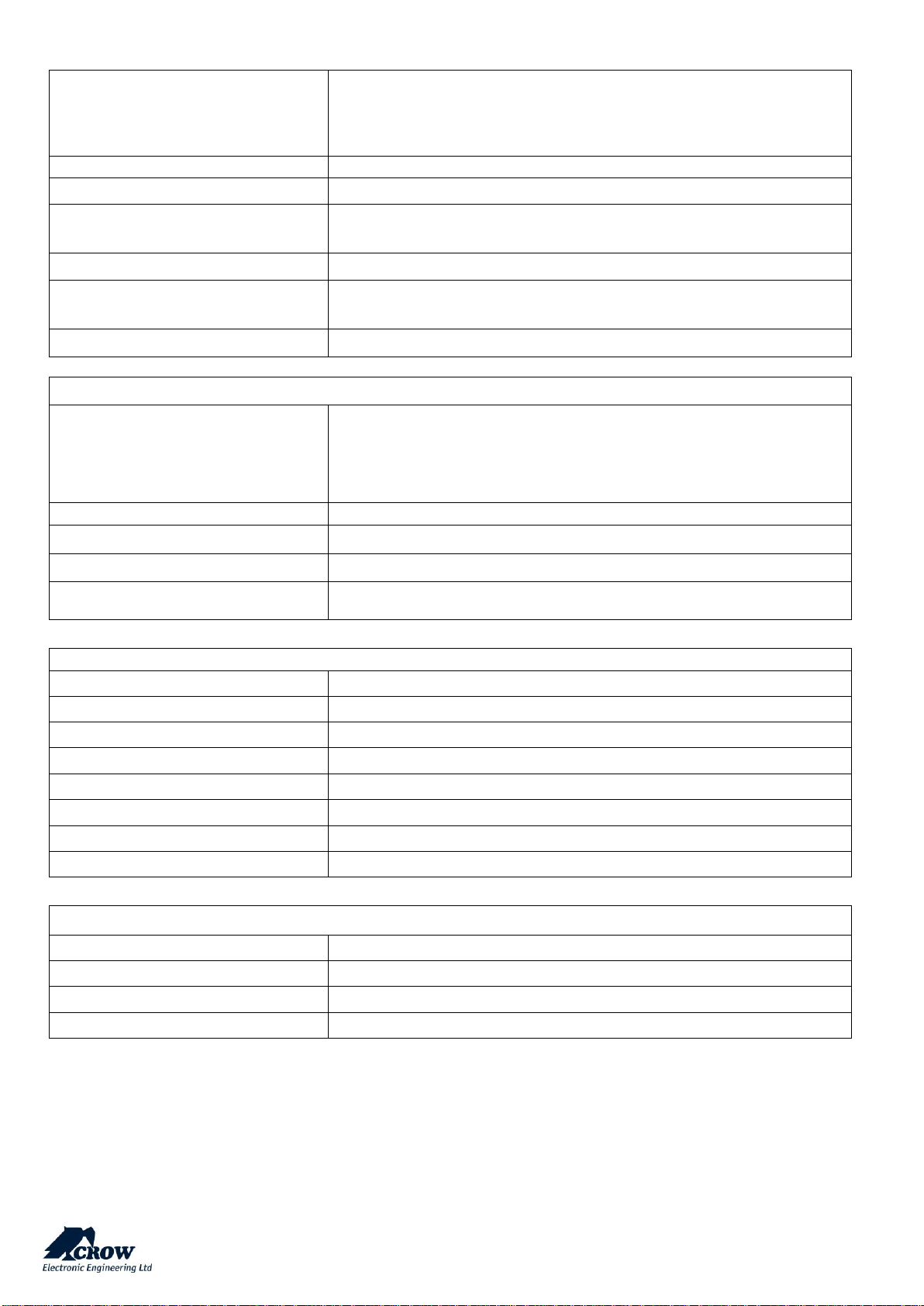
Communication Protocol
Freewave2™ Two Way ISM
GFSK with 5 frequencies & LBT
DECT ULE
Frequency Bands (MHz)
868MHz or 916MHz
Operating Range
Up to 600 meters open space
Zones Number
32 wireless zones
32 DECT devices
Available Partitions
4
Installer and User Codes
1 Installer code
32 Users
Arming Modes
Total, Stay, Latchkey, Duress, Bypass
COMMUNICATION
Capabilities
Built-in TCP/IP module
WIFI Module
GSM 3G Module
DECT ULE Module
Report Channels
8
Audio Verification
Full Duplex Two-way voice communication
Mobile Application
CrowCloud™ (iOS / Android / Web)
Remote Programming
Via Web browser interface
ELECTRICAL
Power Input
230VAC 0.4A, 50Hz
Power Supply Type
Internal AC/DC Adaptor 6V/2A
Low Battery Threshold
3.6V (±0.1V) DC
Backup Battery Type
Battery Pack 3.7V/2600mAh or 3.7V/4400mAh
Time to Charge
Less than 24 hours
Battery Autonomy
More than 12 Hours ( w/o DECT active)
Battery Charge Max current
Approx. 500mA
Current Consumption
Average: 120mA (with DECT active 230mA)
PHYSICAL PROPERTIES
Dimensions
233.8 x 165.8 x 31.6 mm
Weight
1.40Kg with battery
Operating Temperature Range
-10° C to 55 °C
Storage Temperature Range
-20 °C to 60 °C
Security Grade2, Environmental Class II
Power supply Type A
ATS category DP3
Page 7
thecrowgroup.com
Page | 6
Overview & Communication Capabilities
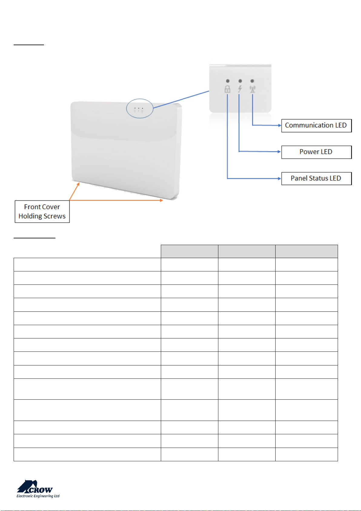
Front View
Led Indications
Status LED
Power LED
Communication LED
System is armed
RED - -
System is in Arm process
RED Blink - -
Burglary Alarm
RED Blink
RED Blink
Panic Alarm
RED Blink
RED Blink
System is disarmed and Ready to Arm
Green - -
System is disarmed and NOT Ready to Arm
Green / RED Blink
-
-
Main power and Back up Battery are OK
-
Green
-
Battery missing OR Battery in charge mode
-
Green / RED Blink
-
AC fail – system working on back up battery Mode
-
Green / RED Blink
-
System working with main communication method
(Ethernet)
-
-
Green Blink
System working with backup communication method
(WIFI or GSM)
-
-
Green / RED Blink
No communication method
- - -
Remote configuration connection
- - Green
WPS mode
Green Blink
Green Blink
Green Blink
Page 8
thecrowgroup.com
Page | 7
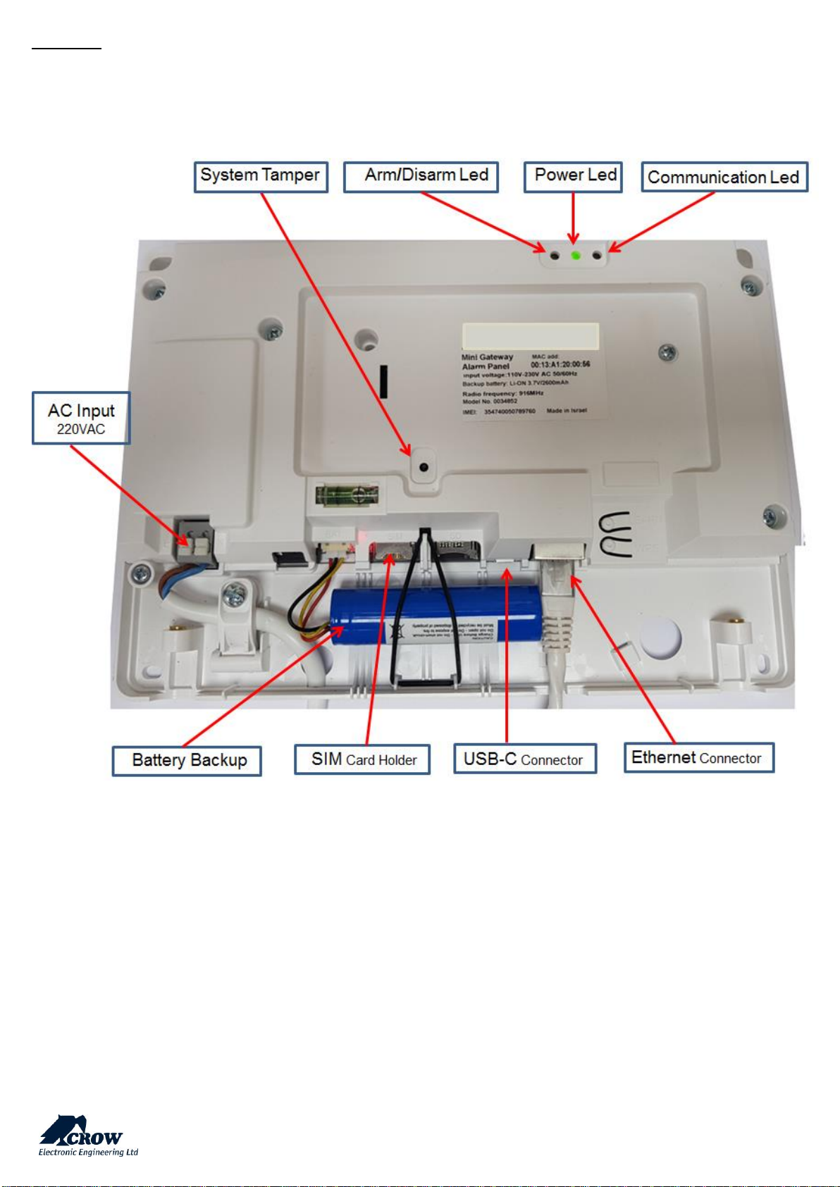
Rear View:
Page 9
thecrowgroup.com
Page | 8
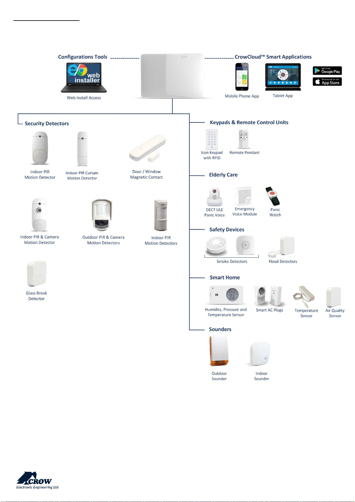
ArchitecturePeripherals
Page 10
thecrowgroup.com
Page | 9
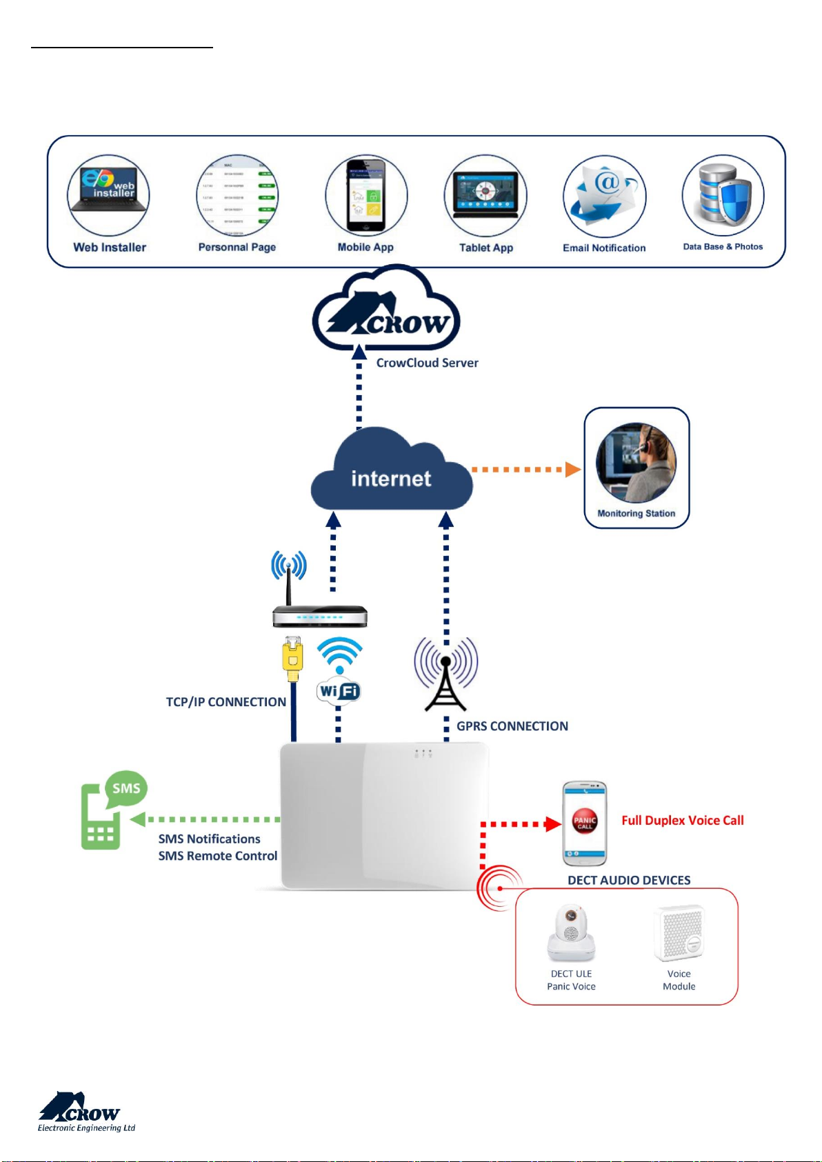
Communication Architecture
Page 11
thecrowgroup.com
Page | 10
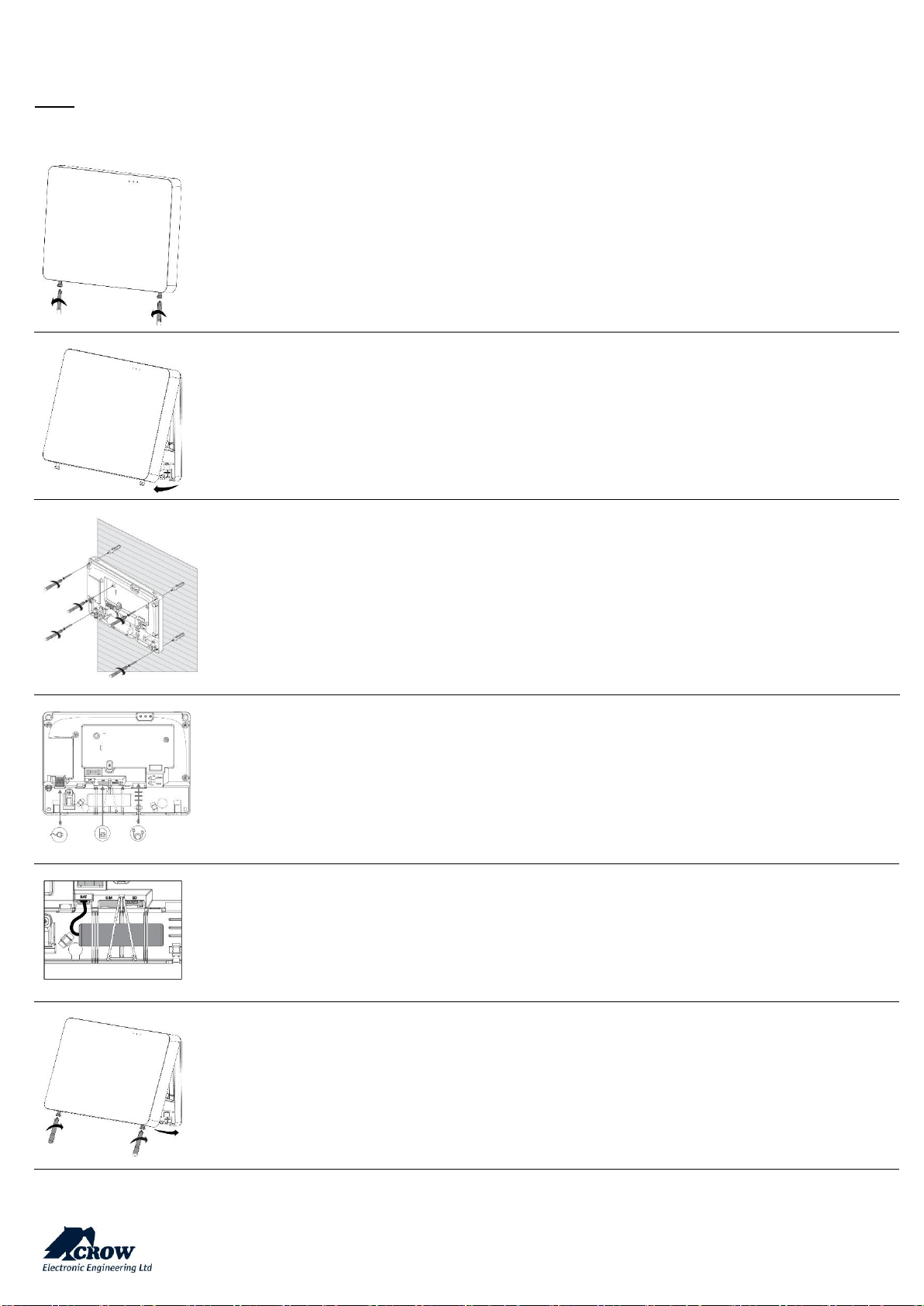
Installing the Shepherd™
Note: Be sure that the control panel is mounted near a socket outlet that is easily accessible. The socket outlet for the power
supply of the control panel should have its own fuse circuit
Use Philips screwdriver to unscrew the 2 holding screws located at the bottom of the panel
The screws are handling by a hidden spring. They cannot be totally removed
Remove the front cover of the panel by tilt it outside
Place the unit on the wall
Use the water level indicator to position it straight on the wall
Mark the holding holes on the wall and drill the wall
Mount the unit on the wall with screws
Ethernet – Connect the Ethernet cable to a router or an internet outlet
GSM – Insert micro-SIM card into the SIM card slot
AC – Plug into a power outlet
Connect the backup battery
Insert back the front cover by tilting it inside
Close the 2 holding screws
Page 12
thecrowgroup.com
Page | 11
Configuring the Shepherd™
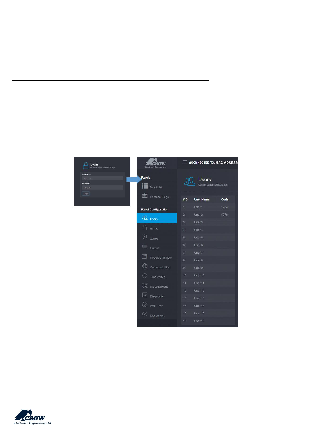
Web Installer Access
After mounting the control panel, connect it to the AC and to the internet via the Ethernet cable plugged into the router.
Note in case the Ethernet connection is not possible or Wi-Fi connection is preferred:
The panel is configured to automatically connect and register on the CrowCloud™.
The configuration of the Shepherd™ panel has to be performed through the web installer interface.
This part of the CrowCloud™ allows access to an online full configuration interface of the Shepherd™ control panel.
The below chapter explains all available options (Version 1.0.0).
Page 13

thecrowgroup.com
Page | 12
Quick Install Guide
Enter the installer code (by default the code is 000000).
For security reasons, it is highly recommended to change the installer code. Go to "Miscellaneous" and change the installer
code in Panel Options and submit.
Users codes and names _________________________________________________________________________________
Shepherd™ panel can manage up to 16 users, click on User to change its code and name.
Learn remote pendant by inserting its unique ID number
Note: to activate pendants, press on the two lower buttons.
Areas Names __________________________________________________________________________________________
Shepherd™ panel offers up to 4 areas (partitions), select the Area to change its name (Ex: Home)
Zones _______________________________________________________________________________________________________________________
Shepherd panels offers up to 64 wireless zones (32 ISM and 32 DECT ULE), click on required zone to display its options.
Insert unique ID number of the device and give it a name.
Set up working mode of the zone (Stay mode, 24-hour…)
Specify Area activation assignment
Note:
The pairing of DECT ULE device must be preliminarily performed from "Communication" → "DECT" → "Learn DECT Device".
When the DECT device pairing is done, then you can go to "Radio Zones" and assign the DECT device ID to a zone between
zones 33 to 64.
Click "Submit" to save changes and activate learned zones.
Outputs ______________________________________________________________________________________________
Shepherd™ panel offers up to 32 wireless outputs (16 ISM and 16 DECT ULE AC Smart Plugs), click on required output to
display its options.
Insert unique ID number of the device and give it a name.
Note:
The pairing of DECT ULE device must be preliminarily performed from "Communication" → "DECT" → "Learn DECT Device".
When the DECT device pairing is done, then you go to "Outputs" and assign the DECT ID to an output between 17 to 32.
Page 14
thecrowgroup.com
Page | 13
Report Channels _______________________________________________________________________________________
Shepherd™ panel offers 4 reports channels types for events communication, click on a report channel to display its options.
Select channel type as follow:
TCP / IP
Set channel type as TCP/IP Need to set Ethernet enabled to use this type of channel
Wi-Fi
Set channel type as Wi-Fi. Need to set Wi-Fi enabled to use this type of channel
GPRS
Set channel type as GPRS 3G.
Need to set 3G IP enabled to use this type of channel in setting "Communication" → "GSM" (see below in para "Communication")
SMS
Set channel type as SMS Text Messages
Active the channel and destination address or phone number, Select the operated protocol ("Crow" by default. Change it if
needed for connection to monitoring station with different Contact ID)
If the selected channel is a backup of another channel, you can edit it.
Communication ___________________________________________________________________________________________________________
Default remote access password is "12345678", we recommend modifying it.
Activate communication paths configured in "Report Channels".
TCP/IP:
By default, the DHCP is active; the router will assign the internal IP of the Shepherd™. You can assign a dedicated IP address
to the panel by filling its static IP, Subnet mask and its Gateway (address of the router).
GSM IP:
This option activates the GPRS. Fill the APN received of your provider.
GSM SMS:
This option activates SMS features if enabled in "Report Channels".
Wi-Fi:
The Shepherd™ panel can connect to the router in Wi-Fi.
Fill the network SSID (name of the wireless network), Security type and network password.
DECT:
Learn DECT devices and go to "Zones" or "Outputs" to assign paired devices.
RF Repeater:
The shepherd™ panel can support up to 4 wireless repeaters. Insert the ID number of repeater.
In case of jamming, you can adjust the RF Channel frequency range between 1 to 5.
Diagnostic ________________________________________________________________________________________________________________
After submitting the configuration, check connections status of the panel:
Battery Status
Ethernet network status with internal connection status.
Wi-Fi connection status
GSM and GPRS status with RSSI level
ISM 2-Way Wireless Radio information
Page 15
thecrowgroup.com
Page | 14
Walk Test _________________________________________________________________________________________________________________
Click on "Start Walk Test" to start the test. Check Zones connection status, device type and RSSI signal of each ISM detectors.
By cross-walking all of the detectors connected to the system and activating them, the associated zone will latch up to allow
verification that all zones are working properly.
The results of the walk-test are displayed on the screen to verify which detectors were triggered during walk-test mode
Press "Exit & Stop Walk Test" button, the walk-test mode will be terminated
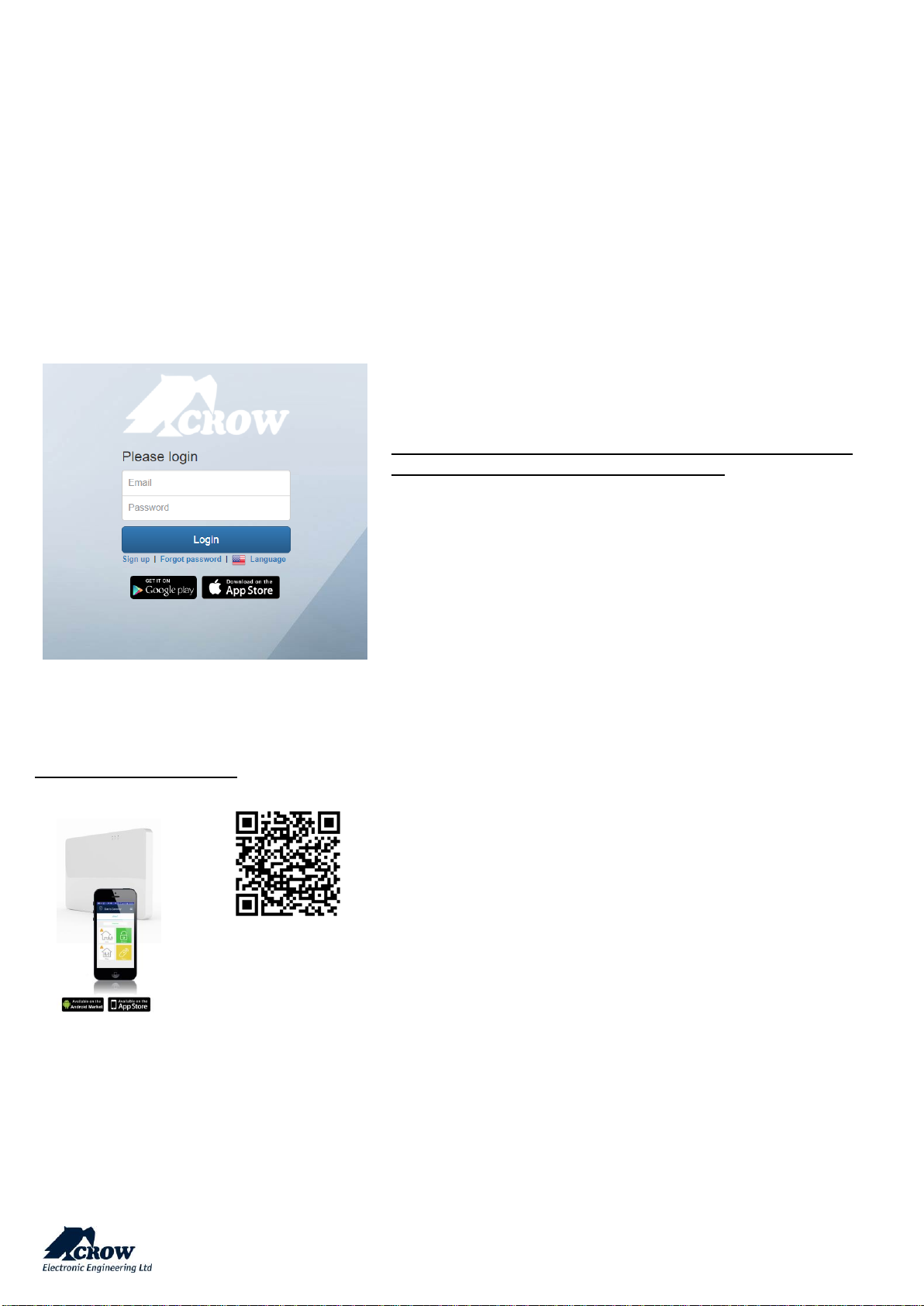
End User Personal Web Page ____________________________________________________________________________
After configuration of your panel, go to http://Crowcloud.com and
proceed with the user registration to your Shepherd™ panel.
The Crow Cloud personal user webpage give to the end user direct
access to all of its registered control panels and:
Monitor and Control panel and connected devices
Browse alarm pictures and request for immediate take picture
Get panel connection info
Manage cloud users
If you already have an account, fill the form and log in or create a new
user account by clicking "Sign Up"
Mobile Applications ___________________________________________________________________________________
Smartphone iOS and Android
Whether you are at home, at work, on a business trip, or on
vacation, The Crow Pro™ application provides you the easiest way
to monitor and control your Shepherd™ :.
• Switch between linked panels (home, office…)
• Control panel state (Arm, Disarm...)
• Check latest events
• See and Operate on active Outputs (Activate/Deactivate)
• See and Operate Zones (Activate/Deactivate Bypass)
• Take picture from connected Pircam(s)
• View stored pictures and Share them (via mail, message...)
• Access to Panel & Users Info
Install the Crow Pro application
on your smartphone
(iOS / Android)
Page 16
thecrowgroup.com
Page | 15
Preliminary Important Note:
Configuration changes will take effect only when you will send the updated configuration to the control panel.
We highly recommend saving your latest configuration before each update.
User Types & Pendants
Click on the user to display its available options.
User Settings
Parameter
Description
Default Configuration
User Name
Enter name of user up to 16 characters
User #
User Code
Enter user code (4-8 digits)
Code 1 defaults to 1234.
This means that User 1
automatically gets the code 1234
Note: Minimum user codes are 10,000
User Options
Parameter
Description
Default Configuration
User code can arm
User can arm all areas that assigned to user
Enable
User code can arm stay
User can arm Stay Mode for all areas that assigned to user
Disable
User code can disarm
User can disarm all areas that assigned to user
Enable
User code can disarm stay
User can disarm Stay Mode for all areas that assigned to user
Enable
Security Guard User
User can arm all areas that assigned to user, but may only
disarm if the panel is currently armed and in the alarm state
Disable
Latchkey Mode User
The User will arm the alarm in Latchkey Mode. If a user with this
option on disarms the alarm no disarm report will be sent via
the dialer. If Latchkey Mode is armed and a user with this option
off disarms the alarm a disarm report will be sent to alert
parents when their children have returned home. Reporting of
Latchkey Disarm is enabled at Reporting Options.
Disable
Page 17
thecrowgroup.com
Page | 16
User Type
Parameter
Description
Default Configuration
Pendant User
Radio keys can be used to Arm/Disarm all or part of the
alarm or they can operate outputs directly', Unlike user
codes, a radio key cannot be assigned to a keypad so if a
radio key is assigned to more than one output and the
radio key is operated, all of the outputs assigned to the
radio key will turn on
Disable
Remote Control User
This option defined user rights for remote control of the
control panel.
Disable
Area Assignment
Parameter
Description
Default Configuration
User Assigned To Area
Codes can be used to Arm/Disarm all or part of the alarm
or they can be used to operate outputs for access control
purposes.
All users assigned to Area 1
Output Assignment
Parameter
Description
Default Configuration
User code turns output ON
Any user can be allowed to turn an Output ON. This
Function can be used to control external devices via the
panel keypad with a User assigned to that Output. Once an
Output is turned ON by a User, the Output can turn OFF
again automatically if a reset time is assigned to the
Output, or it can be turned off by the same user or by a
different user with the next program location
No Outputs selected
User code turns output OFF
Any user can be allowed to turn an Output OFF. This
Function can be used to control external devices via the
panel keypad with a User assigned to that Output. Once an
Output is turned OFF by a User, the Output can be turned
on by the same user or by a different user with the
previous program location
No Outputs selected
Page 18
thecrowgroup.com
Page | 17
Permissions
Parameter
Description
Default Configuration
User can view memory and
status
If this option is off user cannot enter to view memory log,
statuses and active time zones.
Enable for all users
User can change his code and
name
If a User has this option on, they can access User Program
Mode and change their code number and name
Enable for all users
User can change all codes and
names
If a User has this option on, they can access User Program
Mode and change code number and name for all users.
Disabled
User can change phone or
address
If a User has this option on, they can access Client Program
Mode and change the telephone and call divert numbers.
Disabled
User can change the clock
If a User has this option on, they can access Client Program
Mode and change the Time & date settings as well as
daylight saving.
Disabled
User can learn radio devices
If a User has this option on, they can access Client Program
Mode and Learn a new Radio Key or Wireless Zone Device.
They can also remove radio devices or find what location
number a device is stored at.
Enabled for User 1
Pendants
Parameter
Description
Default Configuration
Learn pendant
Save new pendant in memory
Enter the unique serial ID of the pendant and press
Empty
Delete pendant
Delete existing pendant from memory
Confirm deletion and send configuration to panel
-
Pendant can disarm at
alarm only
If this option is enabled, the pendant can disarm the
alarm during alarm only. If this option is off, the
pendant cannot disarm the panel in any state.
Disable
Pendant can disarm at
entry delay only
If this option is on, the pendant can only disarm the
alarm during the entry delay time. This means that
authorized radio key users must enter the building and
trigger the entry delay before the can disarm the alarm.
Disable
Pendant Panic Alarm to
Outputs
A Pendant Panic Alarm can be assigned to an Output or
multiple Outputs. This can be used to operate an
audible or visual alarm connected to the Output
No Outputs selected
Pendant Fire Alarm to
Outputs
A Pendant Fire Alarm can be assigned to an Output or
multiple Outputs. This can be used to operate an
audible or visual alarm connected to the Output
No Outputs selected
Pendant Medical Alarm to
Outputs
A Pendant Medical Alarm can be assigned to an Output
or multiple Outputs. This can be used to operate an
audible or visual alarm connected to the Output
No Outputs selected
Page 19
thecrowgroup.com
Page | 18
Areas Settings
Click on an Area to display its available options.
Area Names
Parameter
Description
Default Configuration
Area Name
Enter name to identify the Area
Area #
Settings
Parameter
Description
Default Configuration
Code required to bypass zones
If this option is turned on, the BYPASS button cannot access
Bypass Mode directly. To enter Bypass mode the User must
press BYPASS CODE ENTER before they can bypass zones
Not Selected
Code required to arm
If this option is turned on, the ARM button is disabled and the
panel requires a code to Arm
Not Selected
Arm command before code to
arm
This option determines if the ARM button must be pressed
before a code is entered to Arm an Area.
Not Selected
Stay command before code to
stay
This option determines if the STAY button must be pressed
before a code is entered to Arm Stay Mode
Not Selected
Report Arm on Exit Delay
If this option is on the panel will report the Arm/Stay Arm
signal to a monitoring station when the exit delay expires. If it
is off, the panel will report the arm signal immediately the
system has been armed
Not Selected
Use near and verified
alarm to report
To reduce the possibility of false alarms the panel can require
two alarms on different zones within a 45 minutes period
before a full alarm is sent. If this option is turned ON it applies
to all zones assigned to that area.
An alarm on a single zone will send a Near Alarm report to the
monitoring station. If no further alarms occur within 45
minutes, the near alarm timer is reset and a restore is sent for
the zone that activated. If the zone that activated is still in
alarm when the 45 minutes timer expires, a zone bypass for
that zone is sent and the zone will remain bypassed until the
area is disarmed. Any new alarms after the timer has expired
will send another Near Alarm report. If a second alarm on a
different zone occurs within 45 minutes of the Near alarm, an
Intrusion Verified alarm report will be sent. This format only
applies to Contact ID and Pager reporting.
Turning this option on will stop zone alarms from being
reported in Domestic & Voice formats as there are no
messages for near and confirmed alarms.
You must turn this option off if using Domestic or Voice
formats
Not Selected
Fail to arm if exit zone still
open
If this option is turned ON it doesn't give to arm or stay arm
the area if one of the low security zones or exit delay zones
still open after exit delay expired. This option not valid for
automatic arm by time zone.
Not Selected
Page 20
thecrowgroup.com
Page | 19
Timers and Delays
Parameter
Description
Default Configuration
Exit Delay Time (sec)
Each Area can have its own exit delay time.
The delay can be programmed from 1-255 seconds in one
second increments. If the exit delay is set to '0' the panel
will be instantly armed.
60 seconds
Area exit stay delay time (sec)
Each Stay Mode Area can have their own exit delay time.
The delay can be programmed from 1-255 seconds in one
second increments. If the exit delay is set to '0' the panel
will be instantly armed.
60 seconds
Area delinquency delay time
(days)
Each Area can have their own Delinquency time.
The delinquency time monitors the arm/disarms of each
Area. If an Area has not been armed within the set number
of days a delinquency report will be sent.
Each time an Area is armed the delinquency timer is reset.
A value of '0' disables the delinquency monitoring.
NOTE:
If the default value of '0' is changed at this location
(e.g. a value of 10 is entered meaning 10 days), the next
time the area is armed a delinquency restore message will
be sent via the dialer as a test that the function is operating
0 second (immediate)
Zone Assignment
Parameter
Description
Default Configuration
Assigned Zones
This option assigns Zone(s) to Area.
If a Zone is assigned only to one area it will activate if
specified area is armed. If zone assigned to more than one
area it will activate only when all assigned areas are
armed. By default all zones assigned to Area 1.
All zones assigned to
Area 1
Areas 2, 3 and 4 not
selected
User Assignment
Parameter
Description
Default Configuration
User Assignment
This option assigns Users to Areas.
If Users have this option activated, they can Arm/Disarm
all zones assigned to Area
All Users assigned to
Area 1
Areas 2, 3 and 4 not
selected
Page 21

thecrowgroup.com
Page | 20
Signals to Output
Parameter
Description
Default Configuration
Arm Area Indication
to Outputs
For monitoring purposes, an Arm indication can be assigned to
an Output.
It could be used to start a video recorder or similar device.
Each Area can have a separate arm indication assigned to a
different output if required
No Outputs selected
Stay Arm Area Indication
to Outputs
For monitoring purposes, a Stay Arm indication can be
assigned to an Output. Each Area can have a separate
indication assigned to a different output if required
No Outputs selected
Disarm Area Indication
to Outputs
For monitoring purposes, a Disarm indication can be assigned
to an Output. Each Area can have a separate disarm indication
assigned to a different output if required
No Outputs selected
Area Armed Exit Delay Beeps
Outputs
This option is using for monitoring purposes of exit delay at
arming by output indication.
If the option marked for specified area corresponded output
will turn to ON during time of arm exit delay.
No Outputs selected
Area Stay Exit Delay Beeps
Outputs
This option is using for monitoring purposes of exit delay at
stay arming by output indication. If the option marked for
specified Area corresponded output will turn to ON during
time of Stay Arm exit delay.
No Outputs selected
Pendant Arm Beep to
Outputs
When Arming the alarm using a Radio Key or Access Tag it is
necessary to have some form of Arm indication. This can be
done by pulsing an Output once when the area is armed (one
chirp).
No Outputs selected
Pendant Stay Arm Beep
to Outputs
When Arming Stay Mode using a Radio Key it is necessary to
have some form of Arm indication. This can be done by pulsing
an Output once when the area is armed (one chirp).
No Outputs selected
Pendant Disarm Beep to
Outputs
When Disarming the alarm using a Radio Key or Access Tag it
is necessary to have some form of Disarm indication.
This can be done by pulsing an Output twice when the area is
disarmed (two chirps).
No Outputs selected
Pendant Stay Disarm Beep
to Outputs
When Disarming Stay Mode using a Radio Key it is necessary
to have some form of Disarm indication.
This can done by pulsing an Output twice when the Stay Mode
is disarmed (two chirps).
No Outputs selected
Arm area Pulse to Outputs
Double pulse will be applied to selected output (e.g. siren)
indicating arming
No Outputs selected
Stay Arm area Pulse to
Outputs
Double pulse will be applied to selected output (e.g. siren)
indicating arming
No Outputs selected
Disarm area Pulse to
Outputs
Single pulse will be applied to selected output (e.g. siren)
indicating disarming
No Outputs selected
Stay Disarm area Pulse to
Outputs
Single pulse will be applied to selected output (e.g. siren)
indicating disarming
No Outputs selected
Pulse outputs every 5 sec at
area disarm
This option will cause the output to pulse every 5 seconds
when the area is disarmed.
The pulse time is linked to the Output Pulse Time.
No Outputs selected
Page 22
thecrowgroup.com
Page | 21
Radio Zones
The Shepherd™ Panel supports up to 64 wireless zones: 32 Two-Way ISM zones (from 1 to 32) and 32 DECT ULE Zones (from
33 to 64).
We invite you to visit our website http://www.thecrowgroup.com for more information on our Two-Way wireless ISM and
DECT ULE detectors range.
To configure Zones, click on the zone to display its related options.
Radio Zones
Parameter
Description
Default Configuration
Name
Enter name to identify the Zone
Zone #
Serial Number
Radio detector must be enrolled into the panel before it can
be used.
Enter the unique radio device ID, and then send the
configuration to the control panel
Note:
The pairing of DECT ULE device must be preliminarily
performed from "Communication" → "DECT" → "Learn DECT
Device".
When the DECT device pairing is done, then you can go to
"Radio Zones" and assign the DECT device ID to a zone
between zones 33 to 64.
Value "0" means no
detector enrolled
Delete
Removing radio zone from the system.
-
Zone Config
This function set remotely the radio zone parameters such as
led on/off, pulse detection, Pet immunity, Gain level, etc.
Dedicated menu
according to detector
type enrolled
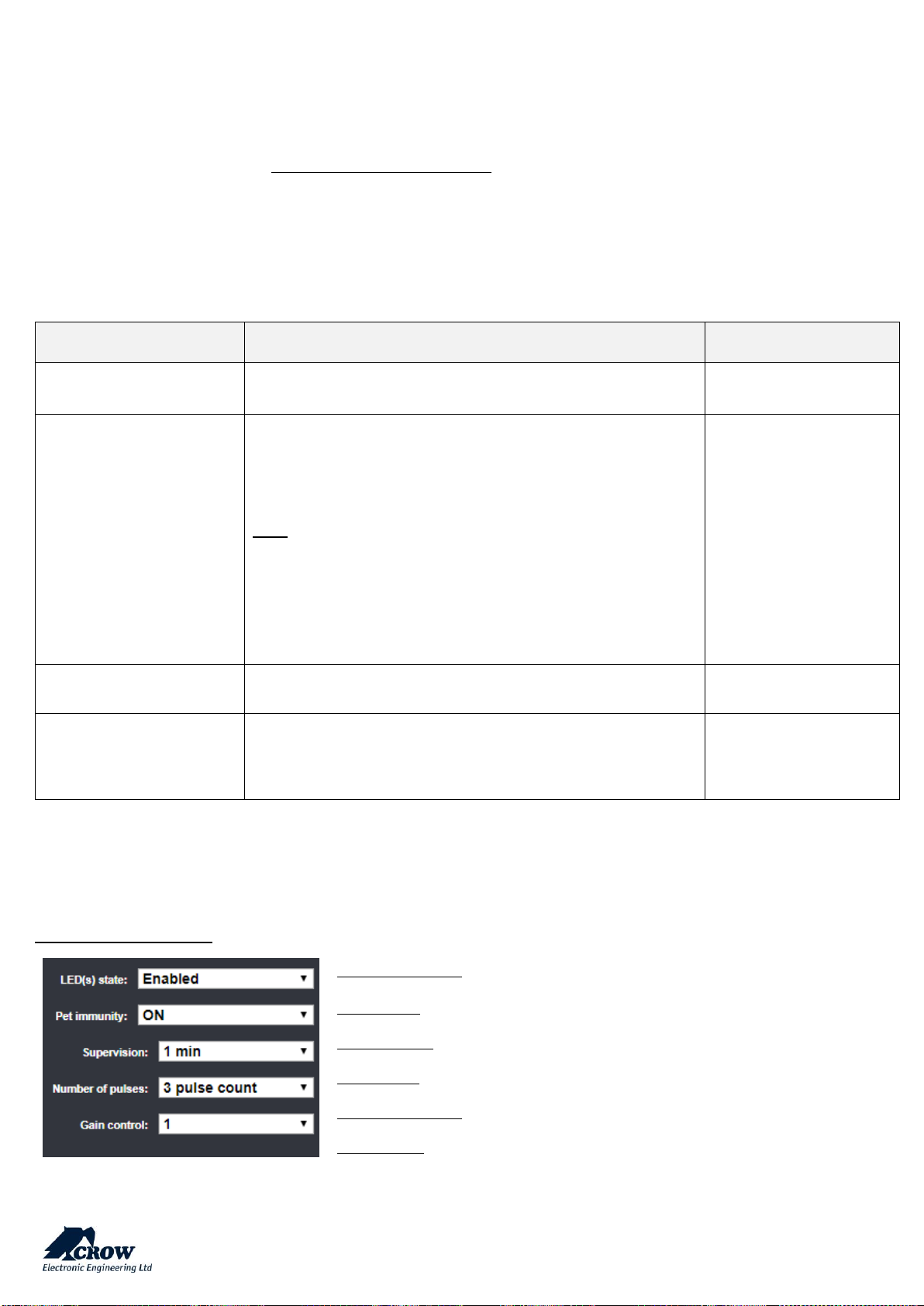
Zone Configuration Menu
Indoor Wireless Detector
Available Options
LED(s) state: Activation or not of the LED indicators
Pet Immunity: Activation of the 15Kg Pet immunity
Supervision: Period between each supervision in minute (from 1 to 30)
Number of Pulses: Pulse count for each motion detection
Gain control: PIR Sensitivity
Page 23
thecrowgroup.com
Page | 22
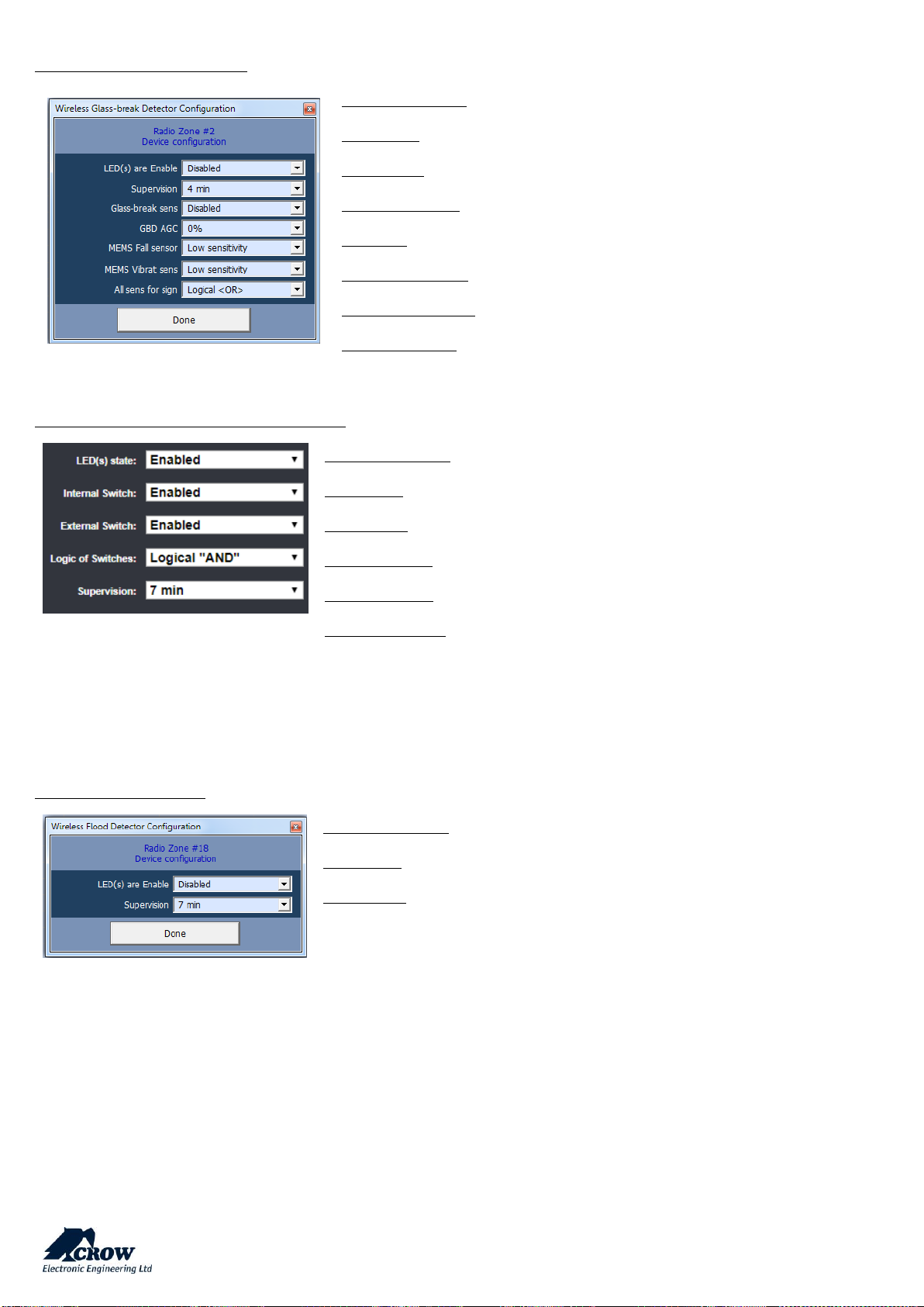
Wireless Glass Break Detector
Available Options
LED Enable: Activation or not of the LED indicators
Supervision: Period between each supervision in minute (from 7 to 30)
Glass-break sens: Sensitivity of the micro elect (Low, Mid or High)
GBD AGC: TBD (0%, 25%, 50% or 75%)
MEMS Fall Sensor:
MEMS Vibrat sens:
All sens for sign:
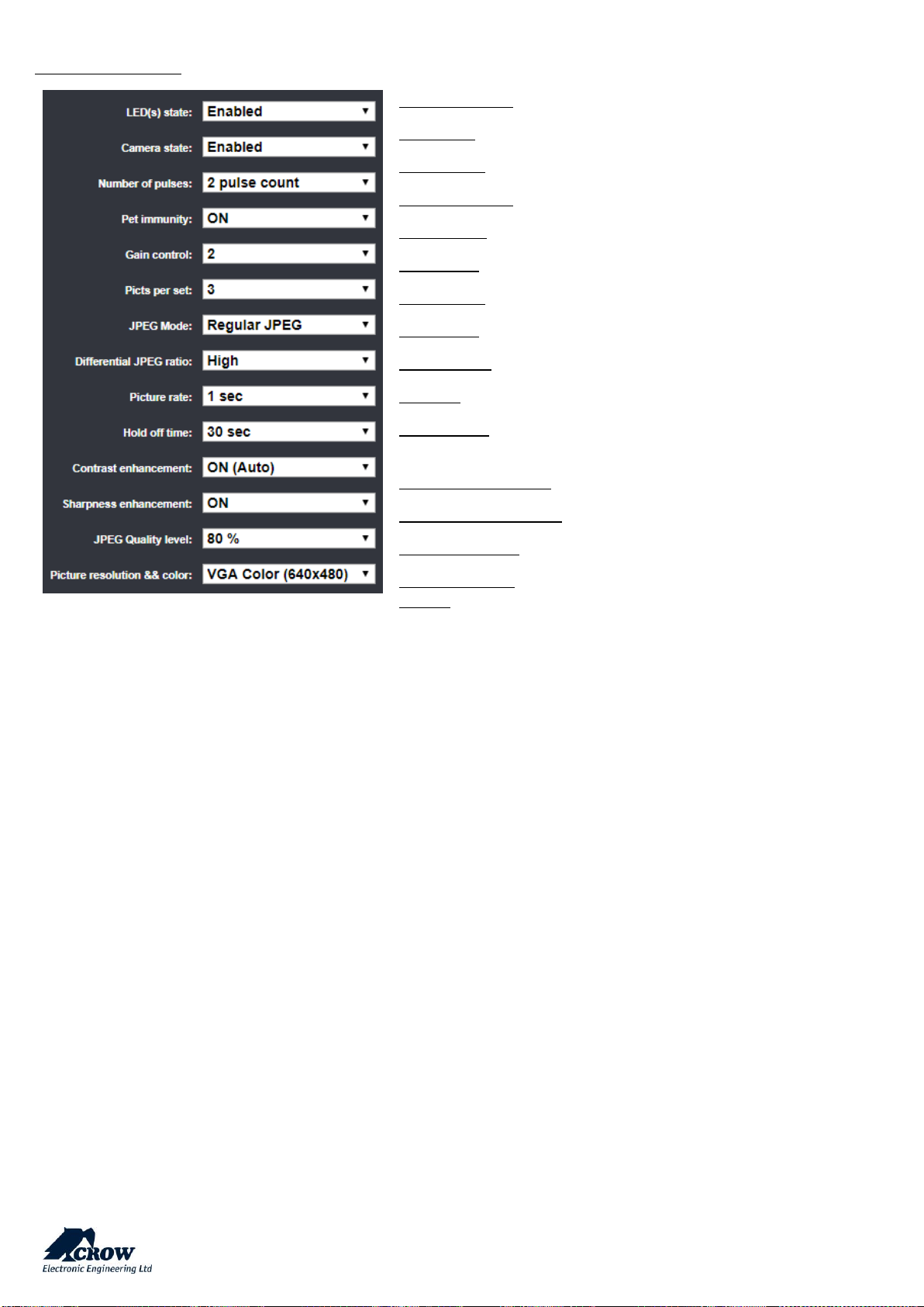
MAG-Wireless Door / Window Magnet FW2
Available Options
LED Enable: Activation or not of the LED indicators
Supervision: Period between each supervision in minute (from 7 to 30)
Internal Switch: Activation of the internal reed switch
External switch: Activation of the internal terminal block (to connect wired device)
Logic of Switches:
AND / OR Mode
Signal will be transmitted if the internal reed switch
(magnet) AND / OR the terminal block is triggered.
Wireless Flood Detector
Available Options
LED Enable: Activation or not of the LED indicators
Supervision: Period between each supervision in minute (from 7 to 30)
Page 24
thecrowgroup.com
Page | 23
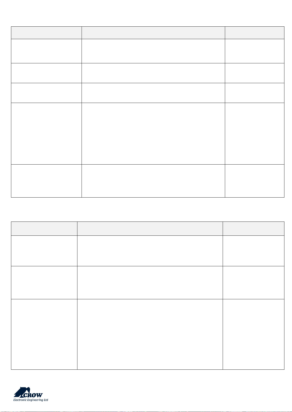
Wireless PIR Camera
Available Options
LED(s) state: Activation or not of the LED indicators
Camera state: Activation of the Camera module
Number of pulses: Pulse count for each motion detection (1,2 or3)
Pet Immunity: Activation of the 15Kg Pet immunity
Gain control: Sensitivity of the PYRO sensor
Picts per set: Number of pictures sent in case of alarm
JPEG mode: Regular or Differential (Video Motion Detection)
Diff JPEG ratio: Sensitivity of the Video Motion Detection (High or Low)
Pict Rate: Time laps between alarm pictures
Hold off (sec): Wait time between 2 detections and pictures (between 30 to
120 sec)
Contrast enhancement: Contrast emphasis of the picture
Sharpness enhancement: Sharpness of the picture
JPEG Quality level: Quality of the picture (from 20% to 90%)
Picture resolution
& color:
Selection between: QVGA B&W (320x240), VGA B&W
(640x480), QVGA Color (320x240), VGA Color (640x480)
Page 25

thecrowgroup.com
Page | 24
Zone Status
Parameter
Description
Default Configuration
Zone is active
Zone will be monitored by the panel.
Non Active until you
learn a new zone
Stay mode zone
Zone will cause alarm if triggered when Stay Mode is armed. This
feature is normally used for arming just part of the alarm at night
time.
All zones selected
Two trigger zone
If this option is ON the zone will have to trigger twice within the two
trigger time before it will cause an alarm. If the zone does not trigger
a second time before the two trigger time expires, the count is reset
and it will take another two triggers to cause an alarm on this zone.
If more than one zone is set-up as a two trigger zone, then a single
trigger from two separate zones within the two trigger time can also
cause an alarm. If the zone becomes faulty and still open once
triggered at end of two trigger time period it will also cause an alarm.
No Zone selected
Exit delay zone
Zone should be closed for ready to arm. It will not cause an instant
alarm if triggered during the exit delay time.
All zones selected
Can Arm if Zone is not
Ready
Zone can remain open during arming and will cause alarm in case it
will remain open after the exit delay expired. This zone is named
"Low Security Zone".
No Zone selected
Handover zone
A Handover Zone is one that its entry delay will apply provided a
Non-Handover entry zone is triggered first. If no other entry delay
zones are triggered before the handover zone the entry delay on
that zone does not apply and the alarm will become instant (no entry
delay)
No Zone selected
Manually bypassed
zone
Zone can be manually bypassed while in the disarmed state. Once
the area with the bypassed zone has been armed and then disarmed,
the manual bypass is canceled and the zone must be manually
bypassed again before arming if required.
All zones selected
Auto bypassed zone
Zone will be auto-bypassed if unsealed at the expiry of the exit delay.
If a zone is unsealed at the time of arming and remains unsealed
when the exit delay expires and this option is on for that zone it will
be automatically bypassed by the panel. If the zone seals after that
time it will be re-instated automatically and can then cause an alarm.
On disarming of the alarm any auto-Bypasses are removed
No Zone selected
Area Assignment
Parameter
Description
Default Configuration
Zone assigned to Areas
This option assigns the Zone to Area. If a Zone is assigned only to
one area it will activate if specified area is armed. If zone assigned
to more than one area it will activate only when all assigned areas
are armed. By default all zones assigned to Area 1.
All Zones assigned to
Area 1 only.
Page 26

thecrowgroup.com
Page | 25
Working Mode
Parameter
Description
Default Configuration
Normal
Zone without any special behavior.
All zones selected
24-hour zone
If this option is ON the zone will be constantly monitored regardless
of the arm/disarm state of the panel. If the 24 Hour zone also has
an entry delay programmed, this delay will apply. Once the alarm
has been generated it must be cleared by entry of a valid User code
No Zones selected
24-hour
auto-reset zone
If this option is ON the zone will be constantly monitored regardless
of the arm/disarm state of the panel. Once an alarm has been
generated with a 24-Hour Auto-reset zone, the alarm will be reset
automatically once the zone is closed. If the 24-Hour zone also has
an entry delay programmed, this delay will apply. If the 24-Hour
zone activates but then resets before the entry delay expires no
alarm will be generated. This feature can be useful for monitoring
plant type alarms such as freezer alarms.
No Zones selected
24-hour fire zone
If this option is ON the zone will be constantly monitored regardless
of the arm/disarm state of the panel. If the 24-Hour Fire zone also
has an entry delay programmed, this delay will apply. Once the
alarm has been generated it must be cleared by entry of a valid User
code.
No Zones selected
Chime
If this option is ON, the zone will operate Chime mode when
disarmed. When the alarm is armed the Chime Mode is disabled for
this zone. A Chime zone can sound the keypad buzzer or operate an
output to indicate that the zone is unsealed. It is normally used to
monitor areas during the daytime
No Zones selected
Permanent chime
If this option is ON, the zone will operate Chime mode when armed
or disarmed. When the alarm is armed the zone will continue to
only be a Chime Mode Zone and will not cause a burglar alarm. A
Chime zone can sound the keypad buzzer or operate an output to
indicate that the zone is unsealed
No Zones selected
Page 27
thecrowgroup.com
Page | 26
Zones Options
Parameter
Description
Default Configuration
Zone will not report 24h
alarm
If this option is turned on and the zone is set as a 24 Hour type,
when an alarm is generated, the alarm will not be transmitted
to the monitoring station via the dialer
No Zones selected
Zone is in Bypass Group
Zone belongs to bypass group. Zones that have been assigned
to the group could be bypassed simultaneously.
No Zones selected
Zone Sends Reports
This option enables the zone to send report function through
all enabled communication channels.
All Zones Selected
Zone is on Soak Test
If a zone is suspected of being faulty and is causing false
alarms, you can turn it into a Soak Test Zone and it will still be
monitored for alarms when armed but it will not cause the
sirens to sound or report to the dialer. The Soak Test zone will
still be logged in the event memory however so it is possible
to check the activity of the zone, via the memory, and after a
suitable period of no alarms it can be re-instated as part of the
alarm by removing the Soak Test option
No Zones selected
Exit Terminator Zone
If this option is selected, when the zone unseals during the exit
delay time and then seals again the panel will cancel any
remaining exit delay time and arm in 3 seconds from the time
the zone was sealed.
No Zones selected
Delays and timers
Parameter
Description
Default Configuration
Armed zone entry delay
time (seconds)
Each Zone has it's own Entry Delay time when in the Full Armed
State. The delay can be programmed from 0 to 9999 seconds in
one-second increments. If the entry delay is set to 0 the zone
will be an instant zone.
All zones are selected
Stay mode entry delay
time (seconds)
Each Zone has it's own Entry Delay time when in Stay Mode.
The delay can be programmed from 0 to 9999 seconds in onesecond increments. If the entry delay is set to 0 the zone will be
an instant zone.
All zones are selected
Sensor watch-time
(minutes)
If value of this option is greater than zero then zone will be
checked to see that it operates during the disarmed state. If it
is not operated within the specified time a 'Sensor-watch' alarm
will be generated. This feature is designed to detect a faulty
zone that is not operating normally or one that has had its
detection area blocked. The timer is stopped when the area
assigned to the zone is armed and resumes with the specified
value when disarmed again. The timer is reset back to the
original value every time the zone operates while disarmed.
The range of values from 0 to 9999 minutes.
All zones are selected
Page 28
thecrowgroup.com
Page | 27
Re-trigger
Parameter
Description
Default Configuration
Zone re-trigger count
Each Zone has its own alarm re-trigger count. A value of 0
programmed at this location results in unlimited alarms for that
zone during an armed period but a count of 1-15 will shut down
the zone once the programmed count has been reached.
Disarming the alarm will reset this count. In case the zone is
assigned to more than one area, this counter should be
multiplied by number of areas (e.g. if zone 1 belongs to A1 & A2,
to achieve re-trigger count = 3, you will need to enter re-trigger
count = 6, because alarm in each area will increment the counter
and common number of re-trigger counts will multiply).
Value "0"
Alarm to Output
Parameter
Description
Default Configuration
Zone alarm to outputs
If an Area is Armed and a zone assigned to that Area activates,
the zone can trigger selected Outputs for local alarm signaling.
This location assigns Zones to Outputs for alarms that occur
when in the Full Armed State
No Outputs selected
Zone stay alarm to outputs
If an Area has Stay Mode Armed and a zone assigned to that
Area activates, the zone can trigger selected Outputs for local
alarm signaling. This location assigns Zones to Outputs for
alarms that occur when Stay Mode is Armed
No Outputs selected
Zone 24H alarm to outputs
If a zone is programmed as one of 24 Hour type zone and if it is
open then the selected output(s) is activated for local alarm
signaling. In case of standard 24-hour zone the output will be
active for the full reset time. In case of 24-hour auto-reset zone
the output is deactivated when the reset time expires or if zone
is closed. If a zone is a 24-hour fire zone then the output will
pulse at a rate equals to the pulse time for that output.
No Outputs selected
Page 29
thecrowgroup.com
Page | 28
Alarm to Outputs (cont)
Parameter
Description
Default Configuration
Zone tamper to outputs
Zone tamper can trigger selected output(s) for
local alarm signaling.
No Outputs selected
Chime zone alarm to outputs
If a zone is programmed as a Chime zone and it
activates, the zone can trigger selected Outputs
for local alarm signaling. The output will operate
for the Chime to Output time at location. The zone
must clear before the output can be activated
again
No Outputs selected
Armed zone entry delay to outputs
If the alarm is Armed and a delay zone triggers the
entry delay it can also turn an Output to ON to
warn that the entry delay is counting down and
the alarm should be turned OFF
No Outputs selected
Zone Stay entry delay to outputs
If Stay Mode is Armed and a delay zone triggers
the entry delay it can also turn an Output to ON to
warn that the entry delay is counting down and
the alarm should be turned OFF
No Outputs selected
Zone near alarm to outputs
If zones are programmed for near and verified
alarms, it is also possible to get an indication of a
near alarm from any of the 16 outputs using this
program location. A near alarm is the first alarm
during an armed period
No Outputs selected
Zone verified alarm to outputs
If zones are programmed for near and verified
alarms, it is also possible to get an indication of a
verified alarm from any of the 16 outputs using
this program location. A verified alarm is the
second alarm from a different zone to the one that
caused the near alarm and must happen within 45
minutes of the near alarm
No Outputs selected
Page 30
thecrowgroup.com
Page | 29
Radio Outputs
Click on the output to display its available options.
Radio Output
Parameter
Description
Default Configuration
Output Name
Set Output Name
Output #
Serial Number
Save new radio Output in memory
Enter the Unique ID serial of the wireless sounder
and save the configuration.
"0" (No Output)
Delete
Delete existing radio output from memory
Press the "Delete" button of the sounder
Confirm deletion by clicking "Yes"
Save the panel configuration
-
Output config
This function set remotely the radio output parameters such
as led on/off, sounder on/off, led and sounder timeouts, etc.
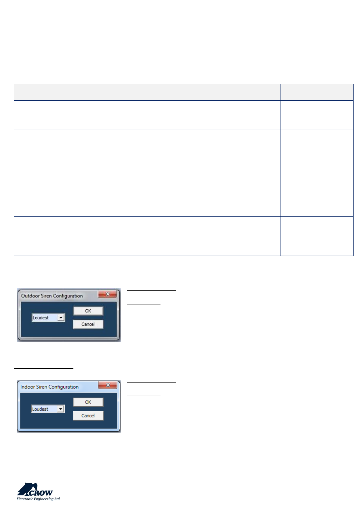
Wireless Outdoor Siren
Available Options
Sound Level: The sound level can be modified as follow:
Quietest
Quiet
Loud
Loudest
Wireless Indoor Siren
Available Options
Sound Level: The sound level can be modified as follow:
Quietest
Quiet
Loud
Loudest
Page 31

thecrowgroup.com
Page | 30
Settings
Parameter
Description
Default Configuration
Invert Output
This option is used to invert the normal state of the output.
The panel uses open collector transistor switches and the
default state of all outputs is OFF (open). When in alarm the
transistor is turned ON and the output goes low (0V). The
invert option reverses this function.
Disable
Temporary Disable output
This option allows a technician to select any output/s to be
temporarily disabled for one alarm or armed cycle, e.g. by
selecting Outputs 1-4 at this location then leaving program
mode, outputs 1-4 will not turn on following any alarms. The
technician is now free to arm the system to test all monitoring
signals without having any internal and/or external alarms
activating. When the alarm is reset or disarmed all outputs will
now work normally again.
Disable
Lockout Output
This option is used to limit the output to one operation per
arming period.
Disable
Pulse Output on Kiss-off after
Arming
This option will cause the Output to be disabled when all areas
in DISARM state. It is designed to keep audible alarms silent
when the full system is disarmed, but part of alarms (like Panic
or Fire alarm) still turns audible alarms to ON regardless of this
setting.
Disable
Disable Output During Disarm
This option will cause the Output to be disabled when all areas
in DISARM state. It is designed to keep audible alarms silent
when the full system disarm, but part of alarms (like Panic or
Fire alarm) still turns audible alarms to ON regardless of this
setting.
Disable
Disable output during report
Delay
This option will cause the Output to be disabled when the
reporting delay is active. It is designed to keep external
audible alarms silent when the reporting delay is active
(allowing internal alarms to warn that the alarm will be
reported to monitoring if not unset) but if the alarm hasn’t
been reset before the timer expires the external alarm will
sound.
Disable
Output muted 10s on keypress if alarm
When the alarm is Armed and activated it can be difficult
sometimes to turn the alarm off because you are unable to
hear the beeps as you enter your code at the keypad. If this
option is turned ON the selected output/s will silence (turn
OFF) for 10 seconds on the first button press at any keypad.
This should allow easy Disarming of the alarm by a valid User.
If the alarm is not turned OFF within the 10 seconds, the
outputs will turn ON again. This function will only work once
during an Armed cycle and the panel must be Disarmed before
it will work again.
Disable
Enable Output Monitoring
If this option is enabled, the control panel monitors the status
of the outputs by voltage level for wired outputs or coming
supervision messages for wireless outputs. If disabled monitoring the state of the outputs will be disabled.
Disable
Enable Mute
TBD
-
Page 32
thecrowgroup.com
Page | 31
Type of Output
Parameter
Description
Default Configuration
Constant
The output will change its state when an alarm occurs
All Outputs are selected
as constant output
Single Pulse
This option produces a single pulse at the output when an
alarm occurs (the pulse time is programmed value).
Not selected
Flash
When the output is turned ON this option causes the output
to flash with a programmed rate. One use is to flash a lamp
during an alarm.
Not selected
Note: you can choose only one type for each output.
User Assignment
Parameter
Description
Default Configuration
Turn ON output from users
Any user can be allowed to turn an Output ON. This Function
can be used to control external devices via the panel keypad
with a User assigned to that Output. Once an Output is turned
ON by a User, the Output can turn OFF again automatically if
a reset time is assigned to the Output, or it can be turned off
by the same user or by a different user with the next program
location.
No User selected
Turn OFF output from users
Any user can be allowed to turn an Output OFF. This Function
can be used to control external devices via the panel keypad
with a User assigned to that Output. Once an Output is turned
OFF by a User, the Output can be turned on by the same user
or by a different user with the previous program location
No User selected
Chime Reset Mode
Parameter
Description
Default Configuration
Chime Alarm Reset
By Signal
The chime state will end when the zone will change its state
Selected
Chime Alarm Reset
By Time
TBD
Not selected
Chime Alarm Reset By
Re-Trigger Time
TBD
Not selected
Page 33

thecrowgroup.com
Page | 32
Signals to Output
Parameter
Description
Default Configuration
Mains Fail to Output
This option is used to assign a Mains Fail alarm to an Output
Not selected
Fuse Fail to Output
This option is used to assign a Fuse Failure alarm to an
Output. The on-board fuses are thermally activated. If
excessive current is drawn from a fuse it will disconnect the
power until the problem is resolved. There are two thermal
fuses protecting the various 12v DC outputs
Not selected
Batt Low to Output
This option is used to assign a Battery Low alarm to an Output
Not selected
Monitor output fail to Output
Assigning monitor output fail alarm
Not selected
Output tamper alarm to
Output
This option is used to assign an Output tamper alarm to an
Output. When output tamper alarm occurs, any output can
be turned ON.
Not selected
Communication
Fail to Output
This option is used to assign a Communication Failure alarm
to an Output
Not selected
Radio Zone Supervised
Fail to Output
This option is used to assign a Radio Detector Supervisory Fail
alarm to an Output
Not selected
System Tamper to Output
This option is used to indication the panel tamper alarm by
specified Output. The Output turns to ON in Arm or Stay Arm
state only.
Not selected
Sensor-Watch to Output
This option is used to assign a Sensor-Watch alarm to an
Output. A Sensor-Watch alarm occurs when a detector has
not operated within a set period of time
Not selected
Duress Alarm to Output
Duress Alarm can be assigned to an Output or multiple
Outputs. This can be used to operate an audible or visual
alarm connected to the Output. A Duress alarm is created
when the alarm is Disarmed with the Duress digit preceding
a valid User Code
Not selected
Walk Test Pulse to Output
When the panel is in Walk-test Mode, this option initiate one
single pulse (one chirp) to the Output every time a zone is
triggered.
Not selected
Page 34
thecrowgroup.com
Page | 33
Timing
Parameter
Description
Default Configuration
Output ON Delay Time
(seconds)
The 'On' delay allows the operation of the Output to be
delayed by the time programmed at this location. If set to '0'
there will be no on delay and the Output will operate the
instant it is turned on. The time range is 0-36000 seconds.
Value of "0"
Output Pulse Time
(seconds)
Output Pulse Time affects the time an output turns on when
the pulse timer is used on the Output. The pulse time is in
1/10th second increments so that very quick timing can be
achieved. The maximum value that could be assigned to is
36000 which corresponds to 1 hour. The parameter valid for
wired outputs only.
Value of "0"
Output Reset Time
(seconds)
The Reset time affects the time the output turns on in case of
an alarm state. The time range is 0-36000 seconds.
Value of "0"
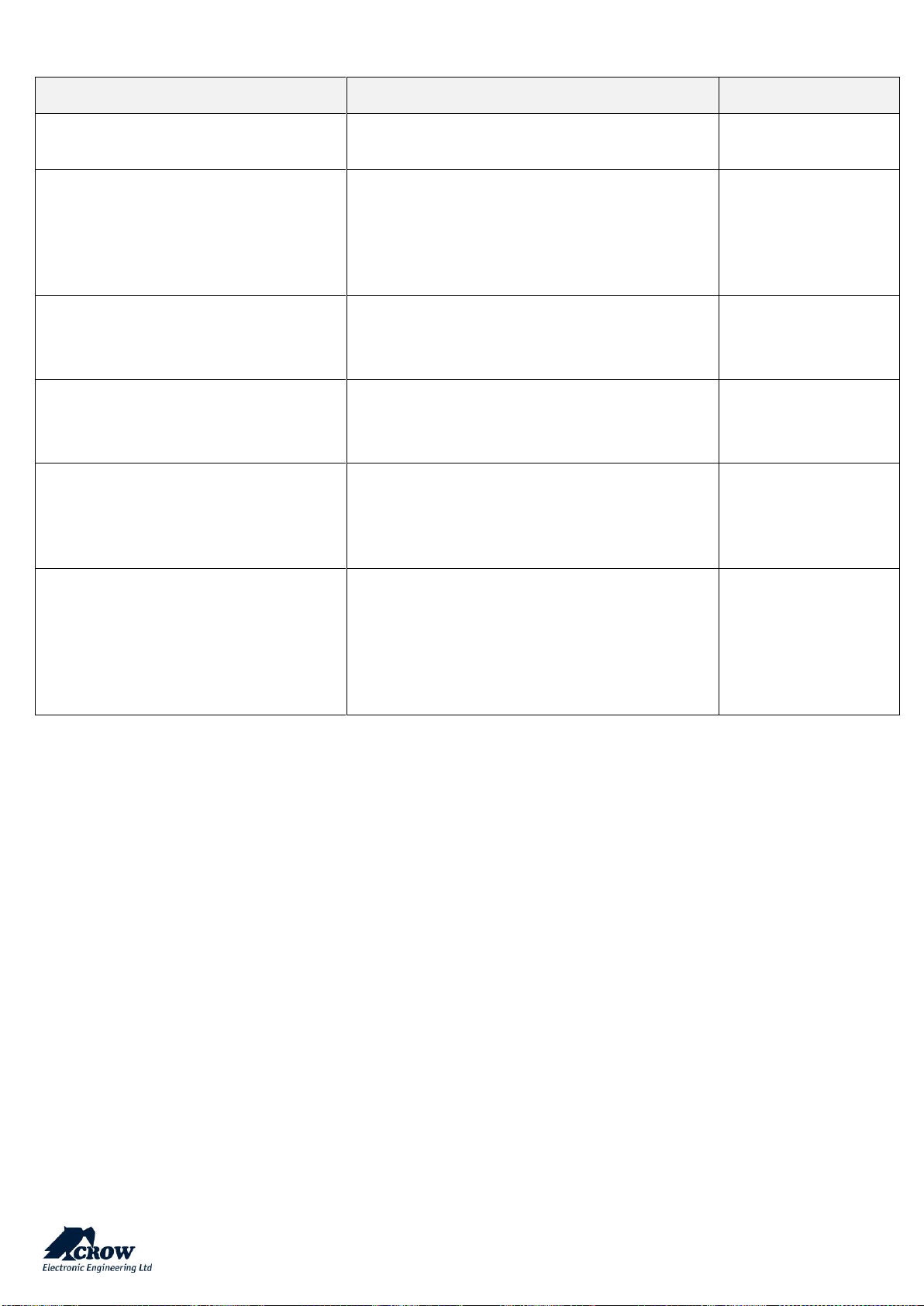
Alarm to Output
Parameter
Description
Default Configuration
Alarm from zones
If an Area is Armed and a zone assigned to that Area activates,
the zone can trigger selected Outputs for local alarm signaling.
This location assigns Zones to Outputs for alarms that occur
when in the Full Armed State
No Outputs selected
Stay Alarm from zones
If an Area has Stay Mode Armed and a zone assigned to that
Area activates, the zone can trigger selected Outputs for local
alarm signaling. This location assigns Zones to Outputs for
alarms that occur when Stay Mode is Armed
No Outputs selected
24H Alarm from zones
If a zone is programmed as one of 24 Hour type zone and if it is
open then the selected output(s) is activated for local alarm
signaling. In case of standard 24-hour zone the output will be
active for the full reset time. In case of 24-hour auto-reset zone
the output is deactivated when the reset time expires or if the
zone is closed. If a zone is a 24-hour fire zone then the output
will pulse at a rate equals to the pulse time for that output.
No Outputs selected
Page 35
thecrowgroup.com
Page | 34
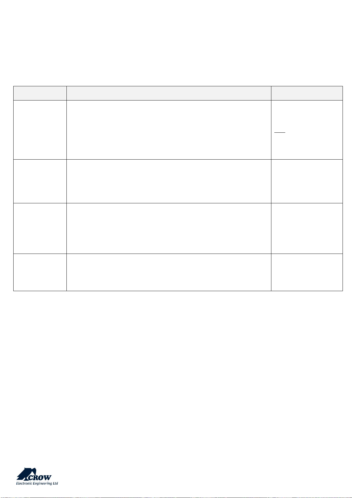
Alarm to Outputs (cont)
Parameter
Description
Default Configuration
Tamper from zones
Zone tamper can trigger selected output(s) for
local alarm signaling.
No Outputs selected
Chime alarm from zones
If a zone is programmed as a Chime zone and it
activates, the zone can trigger selected Outputs
for local alarm signaling. The output will operate
for the Chime to Output time at location. The zone
must clear before the output can be activated
again
No Outputs selected
Entry delay from armed zones
If the panel is Armed and a delay zone triggers, the
entry delay it can also turn an Output to ON to
warn that the entry delay is counting down and
the alarm should be turned off
No Outputs selected
Stay entry delay from zones
If Stay Mode is Armed and a delay zone triggers
the entry delay it can also turn an Output to ON to
warn that the entry delay is counting down and
the alarm should be turned off
No Outputs selected
Near Alarm from zones
If zones are programmed for near and verified
alarms, it is also possible to get an indication of a
near alarm from any of the 16 outputs using this
program location. A near alarm is the first alarm
during an armed period
No Outputs selected
verified alarm from zones
If zones are programmed for near and verified
alarms, it is also possible to get an indication of a
verified alarm from any of the 16 outputs using
this program location. A verified alarm is the
second alarm from a different zone to the one that
caused the near alarm and must happen within 45
minutes of the near alarm
No Outputs selected
Page 36
thecrowgroup.com
Page | 35
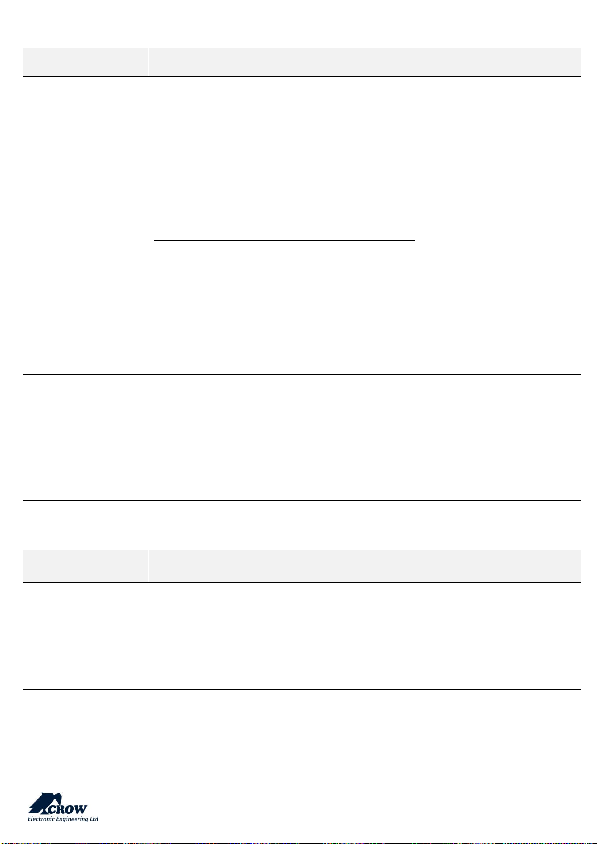
Report Channels
Click on a report channel to display its options.
Channel Type
Parameter
Description
Default Configuration
TCP_IP
Set channel type as TCP/IP
Need to set Ethernet enabled to use this type of channel
Channels #2, #6 and #8
are selected
Note:
The channel #8 is dedicated to
the CrowCloud™™ connection;
please do not change these
settings.
Wi-Fi
Set channel type as Wi-Fi.
Need to set Wi-Fi enabled to use this type of channel
Channel #7 is selected
GPRS
Set channel type as 3G
Need to set 3G IP enabled to use this type of channel in setting
"Communication" → "GSM" (see below in para "Communication")
Channel #3 is selected
SMS
Set channel type as SMS Text Messages
Channels #1, #4 and #5
are selected
Page 37
thecrowgroup.com
Page | 36
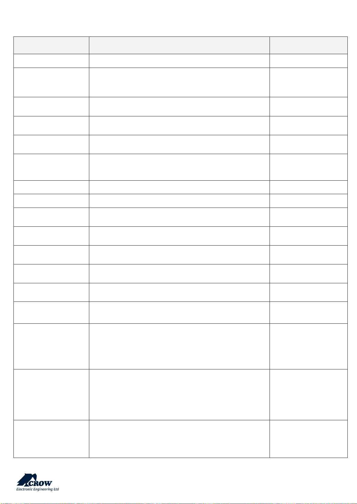
Settings
Parameter
Description
Default Configuration
Channel is active
This option activates or deactivates a report channel for
operations.
Channel #8 activated
only
Destination address
Can be up to 8 phone numbers (for channels defines as
GSM/SMS) or 8 server addresses (for channel defined as TCPIP/GPRS).
The length is up to 50 characters long (digits only for phone
numbers and characters/digits for server address).
No address specified
Protocol
Defines one of the protocol types for each report channel:
Crow
SIA-09(ADM-CID)
SIA-09(SIA-DSC)
This option is available only if the specified channel is defined as
TCP/IP, GPRS or Wi-Fi
Crow predefined
Port
Defines report protocol pot (up to 4 digits)
4700 predefined (Crow)
Channel Backup
This channel will be activated if the main channel has failed to
open connection or deliver a message.
No channels selected
Failed channel restore
time (sec)
If either channel has failed to deliver messages it will be
temporarily disabled for a period of time defined by this
parameter.
During this time, the corresponding backup channel will be used.
3 minutes
Area account numbers
Parameter
Description
Default Configuration
Account Number
When system sends a report to a monitoring station there must
be a unique account number programmed to identify the panel.
There is an account code for each area.
The account code is 4 digits. Each digit can be a number from 09 as well as the special characters B, C, D, E & F. For SMS report
channels no need to define the account number.
All account at "0" except
the channel #8 with
account "8000" for
CrowCloud™ connection
Page 38
thecrowgroup.com
Page | 37
Reporting Options
Parameter
Description
Default Configuration
Video Event Report
This channel transmit Video verification (TBD)
All channels selected
Report Mains Failure
If this option is selected the panel will report a Mains failure
after the report delay time has expired
(see "Clock and Timers" → "Delays")
All channels selected
Report Battery Low
If this option is selected the panel will report a Battery Low
All channels selected
Report Communication
Fail
If this option is selected the panel will report a Communication
failure.
All channels selected
Report System Tamper
If this option is selected the panel will report a Tamper Alarm on
the tamper panel is triggered
All channels selected
Report Keypad Tamper
If this option is selected the panel will report a Tamper Alarm
from a keypad fitted with a tamper switch or a wrong code alarm
from a keypad
All channels selected
Report Zone Tamper
If this option is on the panel will report a Zone Tamper Alarm
All channels selected
Report Duress Alarm
If this option is on the panel will report a Duress Alarm
All channels selected
Report Panic Alarm
If this option is on the panel will report a Panic Alarm generated
by keypad or RMT (pendant)
All channels selected
Report Manual Fire
Alarm
If this option is on the panel will report a Keypad generated Fire
Alarm
All channels selected
Report Manual Medical
Alarm
If this option is on the panel will report a Keypad generated
Medical Alarm
All channels selected
Report Zone Bypasses
If this option is on the panel will report a Manual or Auto Bypass
on a zone
All channels selected
Report Arm-Disarm
If this option is on then all Arm/Disarm signals will be reported
to a Monitoring Station
All channels selected
Report Stay Mode
Arm-Disarm
If this option is on then all Stay Mode Arm/Disarm signals will be
reported to a Monitoring Station
All channels selected
Report Disarm
only after an Activation
If this option is on, the panel will not normally send an
Arm/Disarm signal to the monitoring company, however, if a
zone alarm occurs the panel will send a Disarm following the
disarming of the panel to show it has been turned OFF by a valid
user
No channel selected
Report Stay Disarm only
after an Activation
If this option is on, the panel will not normally send a Stay Mode
Arm/Disarm signal to the monitoring company, however, if a
zone alarm occurs the panel will send a Stay Mode Disarm
following the disarming of the panel to show it has been turned
OFF by a valid user
No channel selected
Report Access to
Program Mode
If this option is on the panel will report a Contact ID code to
indicate that either Client or Installer program Modes have been
accessed
All channels selected
Page 39
thecrowgroup.com
Page | 38
Parameter
Description
Default Configuration
Report Zone Restores
If this option is on the panel will report all zone restores. If this
option is turned off the panel will only report the alarms
All channels selected
Report Delinquent
If the panel has been configured for Delinquency monitoring and
an area has not been armed for the time set at, a Delinquency
Alarm will be sent to the Monitoring Station
All channels selected
Report Fuse Failure
The panel has two on-board thermal fuses designed to protect
the 12v DC outputs from short circuits. If this option is on and
either of these fuses are open, a report will be sent to the
monitoring station if Contact ID is set as the reporting format
All channels selected
Report Radio Battery
Low
If this option is on the panel will report a Battery Low from any
radio zones that have the battery status monitored
All channels selected
Report Supervised Radio
Alarm
If this option is on the panel will report a Supervised radio Alarm.
All channels selected
Report Zone Sensorwatch Alarm
If this option is on the panel will report a Zone Inactivity (Sensorwatch) Alarm.
All channels selected
Report Latchkey Disarm
When this option is turned ON and the panel was armed in
Latchkey Report Mode, at Disarming by a non-latchkey user the
specified latchkey disarm report will be sent via voice or SMS
report channel to user, marked as latchkey mode user.
All channels selected
Report Communication
Interference Detected
If the radio receiver detects Communication Interference
(Jamming) of the radio frequency, the panel can report this
event to the monitoring station if this option is turned on
All channels selected
Report Output Fail
If this option is on and a fault is detected on the output, a report
will be sent to the monitoring station if Contact ID is set as the
reporting format
All channels selected
Report Tests
If this option is selected, the panel can send automatic test
connections, but if test connections are not required, they can
be disabled by turning this option off.
All channels selected
Report Stay Mode Zone
Alarms
If this option is on, the panel will report zone alarms in Stay
Mode
All channels selected
Report output changed
The changing output state will be reported via SMS reporting to
the user
All channels selected
Report Peripheral
Tamper
If this option is on the panel will report a Tamper Alarm from a
peripheral module (extender module or radio output) fitted with
a tamper switch from a peripheral module
All channels selected
Report Zone Confirmed
Alarm
If this option is on the panel will report a Zone Confirmed
(Near and Verified) Alarms.
All channels selected
Page 40
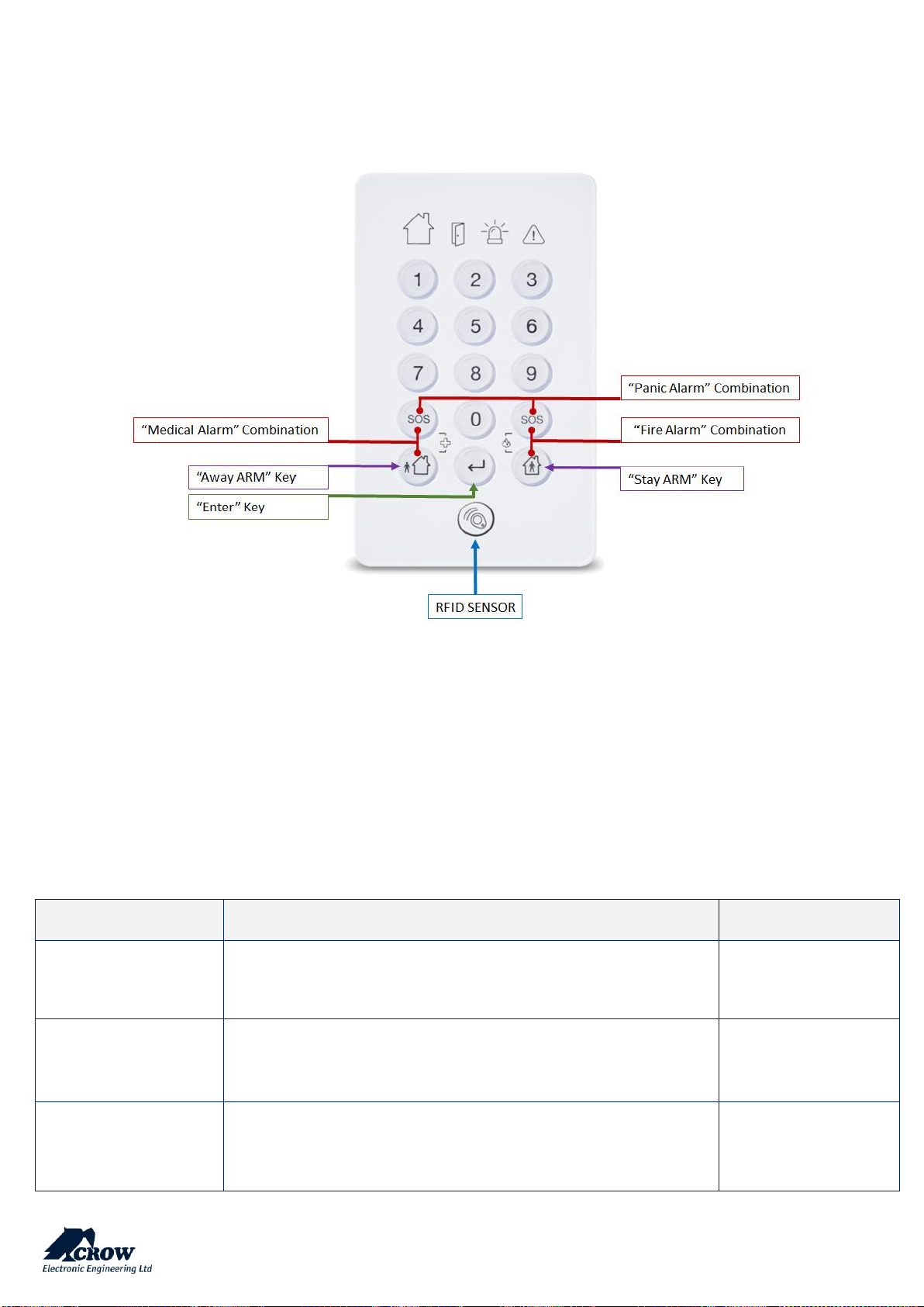
thecrowgroup.com
Page | 39
Radio Keypads
SH-KP Icon Keypad Overview
The SH-KP is an optional two-way wireless keypad with built-in proximity RFID tag reader compliant with RFID tags including
variation of millions ID combinations and numerical keypad.
For RFID control, please use access tag. Press the key "Enter" and serve the tag.
For learning procedure, please refer to the para "Radio Keypad" below.
For additional information on the SH-KP please refer to its manual.
Settings
Parameter
Description
Default Configuration
Serial Number
Enter the unique ID serial of the wireless keypad.
Press "Done" and upload the configuration
Value "0"
Delete Keypad
Press the command button to delete keypad
-
Keypad Config
Configuration of Fast Arm, Fast Stay Arm and Keypad Loudness
-
Page 41
thecrowgroup.com
Page | 40
Parameter
Description
Default Configuration
Enable Beeps
Enable beeps on selected keypad
Beeps enabled on
keypads 1 and 2
No armed indications
This option allows the information on a keypad to be turned
OFF when the panel is in the Armed or Stay Armed state. The
screen returns to the normal state on disarming of the system.
No Keypad selected
Area Assignment
Parameter
Description
Default Configuration
Keypad Assigned To
Area
This option assigns Area to keypads.
If a keypad is assigned to one area only it can Arm or Disarm only
that area and show states only for this area. If keypad assigned to
more than one areas, it can be switched to operate specified area
and show states.
All keypads assigned to
Area 1
User Assignment
Parameter
Description
Default Configuration
User can operate at
keypad
Any user can be assigned to only operate at certain Keypads.
This option controls whether a code or access tag User can
Arm/Disarm from certain keypads. This option does not restrict
users from operating outputs from a particular keypad.
All Users can operate
on All Keypads
Alarm to Output
Parameter
Description
Default Configuration
Keypad Panic Alarm
to Output
A Keypad Panic Alarm (pressing C & D buttons together) can be
assigned to an Output or multiple Outputs. This can be used to
operate an audible or visual alarm connected to the Output
No Keypad selected
Keypad Fire Alarm
to Output
A Keypad generated Fire Alarm (pressing the A & B together) can be
assigned to an Output or multiple Outputs. This can be used to
operate an audible or visual alarm connected to the Output
No Keypad selected
Keypad Medical Alarm
to Output
A Keypad generated Medical Alarm (pressing the B & C together) can
be assigned to an Output or multiple Outputs. This can be used to
operate an audible or visual alarm connected to the Output
No Keypad selected
Page 42
thecrowgroup.com
Page | 41
Communication Options
Remote Access
Parameter
Description
Default Configuration
Remote Access
Password
It is defined up to 8 characters password for remote connection
(CrowCloud™ and Mobile applications)
12345678
Remote Access
Server Address
This parameter defines IP-address or DNS name of the remote
access server.
mediator.CrowCloud™.xyz
(CrowCloud™ server address)
Remote Access
Server Port
This parameter defines the port on remote access server the
control panel using fore registration procedure.
4701
(CrowCloud™ server port)
Communication Options
Parameter
Description
Default Configuration
Phone number for
remote control
Enter the number phone for remote control
-
TCP/IP
Parameter
Description
Default Configuration
Ethernet Enabled
If this option is selected, the Ethernet connection is Enabled.
Enabled
DHCP Enabled
If this option is selected, the DHCP is Enabled.
The server will automatically assign an IP address to the control
panel.
Enabled
Static IP
In the absence of DHCP, the control panel must be manually
configured with an IP address, subnet mask, Panel, DNS server.
Empty
Subnet Mask
The network subnet mask for defined static IP address.
Empty
Gateway
IP Address of the router/server.
Empty
DNS Server
The network DNS server address for defined static IP address.
Empty
TCP/IP Port for Remote
Control
The number of incoming TCP/IP port using for remote control
applications.
3064
Page 43
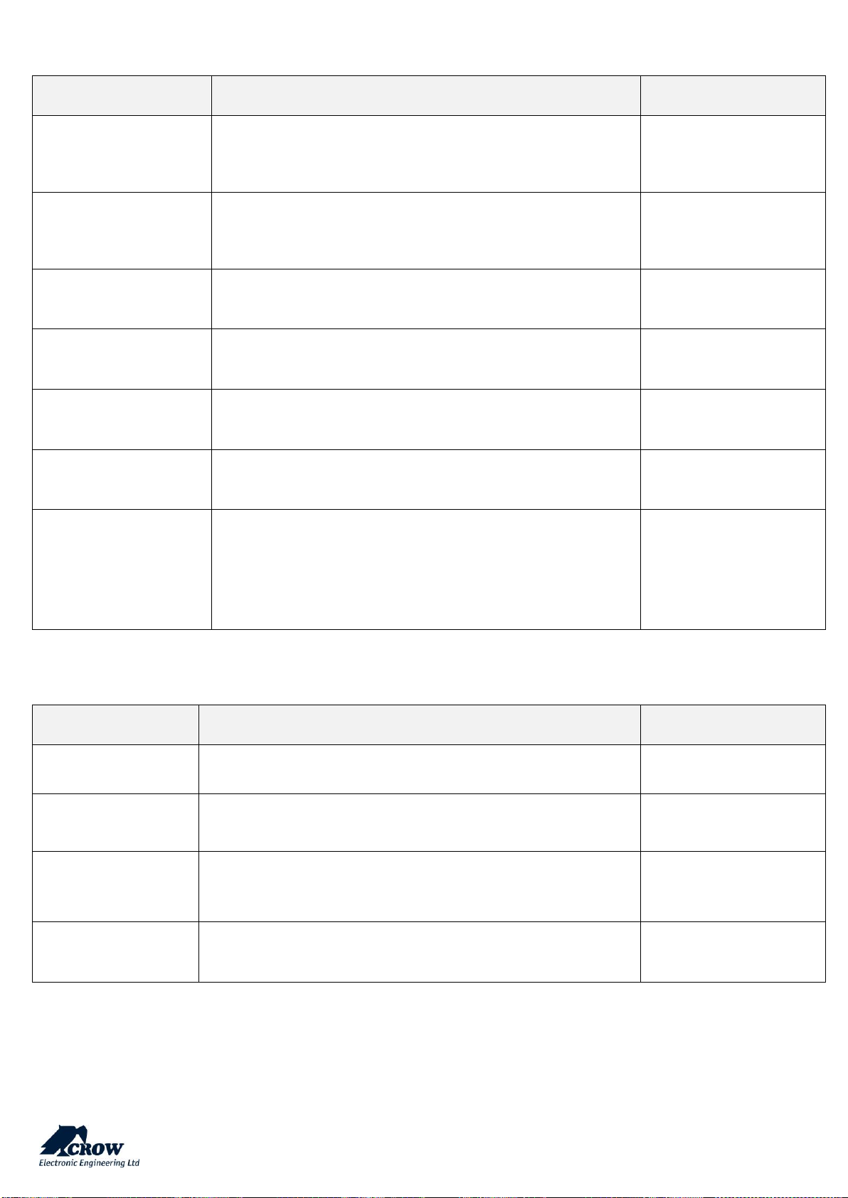
thecrowgroup.com
Page | 42
GSM
Parameter
Description
Default Configuration
GSM IP Enabled
If this option is on, the GPRS Data is Enabled.
This communication method suits for Data connection to
Monitoring Station or Server.
Enabled
GSM SMS Enabled
If this option is on, the GSM CID is Enabled.
This communication method suits for connection to Monitoring
Station, SMS Text (in English only).
Enabled
PIN Code
GSM PIN code number according to GSM network requirements,
up to 8 digits length.
No PIN Code
GSM User
GPRS user according to APN GSM network requirements.
Empty
GSM Password
GPRS Password according to APN GSM network requirements.
Empty
GSM APN
GPRS APN access point name according to your cellular provider.
"internet"
USSD Code
Unstructured Supplementary Service Data (USSD) is a protocol
used by GSM cellular telephones to communicate with the
service provider's computers, using for prepaid callback and
mobile-money services. The parameter contains 3 decimal
digits.
0
Wi-Fi
Parameter
Description
Default Configuration
Wi-Fi Enabled
If this option is selected, the Wi-Fi connection is Enabled.
Disabled
SSID
This is the name of the wireless network you want to connect to.
Empty
Security Type
Select the security type of your Wi-Fi network
"Open" – No Encryption
Password
Password of the wireless network you want to connect to.
Empty
Page 44
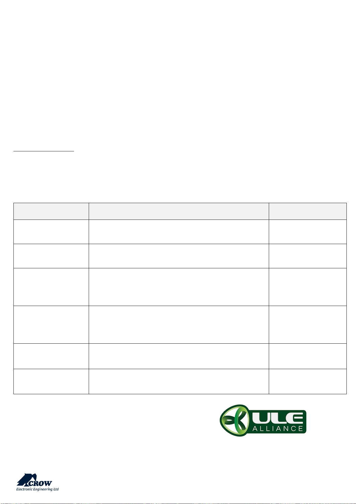
thecrowgroup.com
Page | 43
DECT
What is DECT ULE?
ULE addresses Ultra-Low Energy application requirements by introducing optimized communication methods. Identified with
low power consumption, low latency, long range, moderate data rate and value-added complementary voice capabilities,
ULE is the best-of-class technology, which represents the next evolution in home networking.
ULE is based on DECT (Digital Enhanced Cordless Telecommunications) which is the de-facto standard for residential and
business cordless phone communications worldwide.
DECT ULE is an SW protocol extension of the standard DECT, These devices can be easily support DECT ULE for Home
Automation and Security/Monitoring.
DECT ULE: the perfect combination of long battery lifetime, high data rate, low cost and long transmission range.
Frequency Allocations:
Europe: 1880-1900 MHz
China: 1900-1920 MHz
Japan: 1893-1906 MHz
Latin America: 1910-1930 MHz
US & Canada: 1920-1930 MHz
Parameter
Description
Default Configuration
DECT Enabled
If this option is selected, the DECT Module is Activated.
Enabled
DECT Contact Number
Phone numbers of the contact persons called from the Audio
Panic DECT button
Empty
Learn DECT Device
DECT detector must be enrolled into the panel before it can be
used.
Click this button to start DECT pairing process
-
Delete DECT HAN Device
Removing DECT device from the system.
Select the device you want to delete and press the button
Confirm deletion and save the configuration
ID of the DECT device
Delete DECT HS Device
Click this button to delete DECT Panic Button
Empty
DECT PIN Code
PIN code of the DECT voice unit (if needed)
Empty
Crow Electronic Engineering Ltd. Is an active contributor to
the ULE Alliance with a full range of DECT ULE products
Page 45
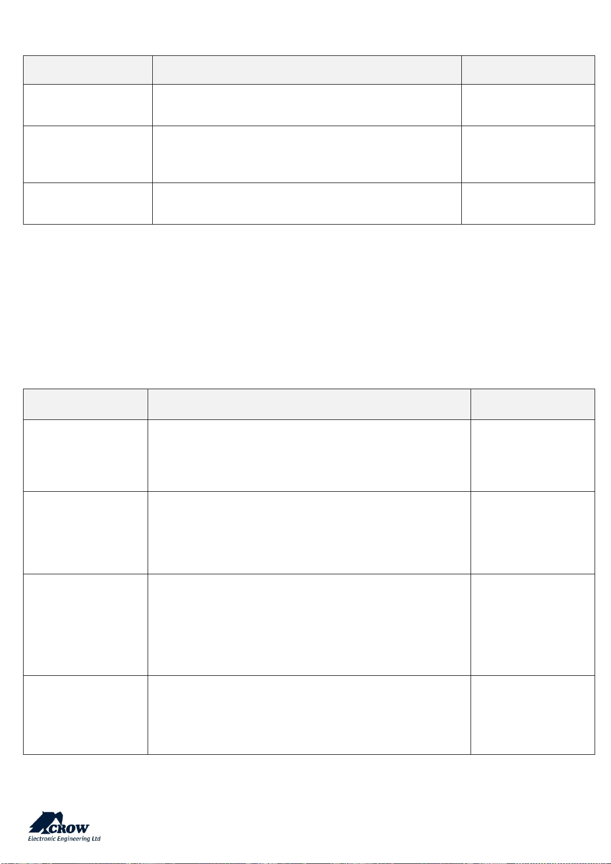
thecrowgroup.com
Page | 44
RF Repeater
Parameter
Description
Default Configuration
Starting RF Channel
The Repeater supports up to 5 frequencies to prevent jamming.
You can choose frequency range from 1 to 5.
1
Learn Repeater
Enter the unique ID of the device
Press Done and Save the configuration
-
Delete Repeater
Click this button to delete the selected wireless repeater
-
Time Zones
Click on the Time Zone to display its options.
Settings
Parameter
Description
Default Configuration
Start Time
The Time-zone start time is when the time-zone begins. The time
using for arm of area(s), turns output(s) to ON state and activate
rights of specified user(s). There are 8 time-zones that can be
programmed.
HH:MM
End Time
The Time-zone end time is when the time-zone finishes. The time
using for disarm of area(s), turns output(s) to OFF state and
deactivate rights of specified user(s). There are 8 time-zones that
can be programmed.
HH:MM
Password
Password to activate/deactivate the selected Time Zone
When this option is not empty then time-zone is inactive until user
enters valid password. After that time-zone behaves like an
ordinary time-zone. By entering valid password once again user will
deactivate time-zone. When time-zone start time expires then
area(s) assigned to time-zone will arm after 2 sec delay.
Empty
Time Zone Days
The Time-zone days are the days of week that the time-zone will be
active. You can select any combination of the days from Sunday till
Saturday. There are 8 time-zones that can be programmed.
No Day selected
Page 46
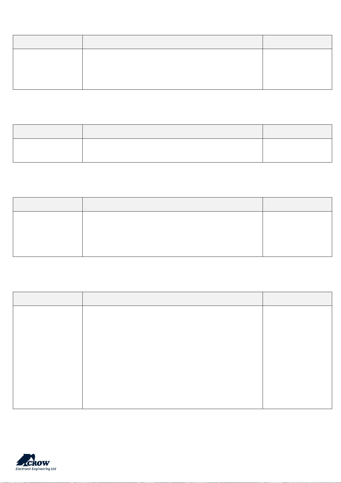
thecrowgroup.com
Page | 45
Area Assignment
Parameter
Description
Default Configuration
Time Zone Assigned to
Area
If area assigned to time-zone it will automatically arm when timezone starts and disarmed when it finishes. You can assign more than
one time-zone to each area. If assigning multiple time-zones you
should insure that they do not overlap as this could cause
confusion.
No Zones selected
Output Assignment
Parameter
Description
Default Configuration
Time Zone Assigned to
Output
If a time-zone is assigned to an output it will turn the output on
when the time-zone starts and turn the output off when it finishes.
No Output selected
User Assignment
Parameter
Description
Default Configuration
User Controlled by Time
Zone
When the user is controlled by time zone, its keypad code, access
tag and pendant deactivated all the time, when the time zone is not
started or finished. Only when the time zone is started, the user can
perform actions in the system in accordance with its rights as
defined by configuration.
No User selected
Time Zones holidays
Parameter
Description
Default Configuration
Holidays
It is possible to pre-program up to 8 holidays. Holidays can override
the time-zone function on the programmed day. For example, if an
output was automatically controlled by a time- zone, the preprogrammed holidays can stop the output from turning on or off on
a holiday. A holiday consists of a single day programmed by date.
The holiday begins at the start of the day (00:00:00) and finishes
immediately before midnight (23:59:59) on the programmed date.
Holidays can be programmed in any order (although for simplicity
it is recommended that they are programmed in chronological
order) and the panel automatically removes them once the day
ends. If you wish to remove a programmed holiday, you should to
clear the date field.
Page 47

thecrowgroup.com
Page | 46
Miscellaneous
Clock and Timers
Parameter
Description
Default Configuration
Daylight Saving
If you are in Daylight Saving Time when the alarm system is installed
you MUST turn this option ON so that the panel knows that Daylight
Saving Time is currently active.
Failure to do this will not allow the clock to automatically adjust to
the correct time when Daylight Saving Time Ends
Not Enabled
GMT
Time zone starts from Greenwich Mean Time (GMT 0)
Value "2" for GMT+2
Date Format
European date format: Day / Month / Year
American date format: Month / Day / Year
European format
selected by default
Radio Zone Supervised
Time ( in minutes)
If a radio detector is capable of sending regular supervisory signals
to the panel and the zone type is set for 'Supervised Signal Active',
this timer sets how long a period has to elapse with no received
transmissions before a supervisory failure alarm is generated. The
time range is 1-255 minutes.
63 (minutes)
Two Trigger Time
(in seconds)
If a zone is set to two trigger, the zone has to cause an alarm twice
within the two trigger time period to cause an alarm. If multiple
zones are set to two trigger, an alarm will be generated it two zones
trigger once each within the two trigger time period. If a two trigger
zone goes into alarm but remains in alarm for longer than the two
trigger time period (ie detector failure or cable cut) an alarm will be
generated. The time range is 5-255 seconds.
10 (seconds)
Alarm Reporting Delay
(seconds)
If this address is set to 0, there will be no report delay. If it is set to
any value other than 0 then a delay equal to the programmed value
will stop the panel from reporting an alarm until this delay time
expires. While the timer is active certain outputs can be disabled.
Once the timer has expired it will not start again, the panel must be
disarmed then armed to reset the timer. The value in seconds,
maximal limit is 255 seconds.
0
Mains Fail Reporting
Delay (seconds)
If a Mains Failure occurs this timer delays the reporting of Mains
Failure to a Monitoring Station. If the mains power returns before
the timer expires, then no report is sent. If Mains Failure is assigned
to an output, this delay must expire before the output will turn on.
The value in seconds, maximal limit is 3 hours (10800 seconds).
900
Communication Fail
Reporting Delay
(seconds)
If a Communication Fail occurs this timer delays the reporting of
Communication Fail to a Monitoring Station. If specified
communication path returns before the timer expires, then no
report is sent. If Communication Fail is assigned to an output, this
delay must expire before the output will turn on. The value in
seconds, maximal limit is 3 hours (10800 seconds).
0
Page 48
thecrowgroup.com
Page | 47
Panel Options
Parameter
Description
Default Configuration
Installer Code
This code is used to enter into full Installer Program mode.
This code can only be changed while in Installer Program Mode.
The Installer Code must be between 4-8 digits in length
000000
Duress Digit
The duress digit can be a number from 1-9 (a value of '0' means
the duress function is disabled).
To create a duress alarm the duress digit must be entered before
a valid user code (eg If the code was '123' and the duress number
was '4', then entering a code of '4123+ ENTER' would create a
duress alarm).
Any user code or time-zone password cannot starts with this
digit for right duress recognition.
0
Disable mains fail test
If the panel must be run off a DC supply or the Mains supply can
fail regularly, this option disables the mains voltage monitoring
to prevent mains fail alarms from occurring
Not selected
Installer Lockout
If this option is selected, the panel will not allow access to
program mode on power-up and the only valid method of
accessing program mode is via the installer code.
Not selected
Buzzer Reset Time
Buzzer Reset Time in minutes
1 minute
Config mode resets
confirmed alarms
If this option is selected and a Confirmed alarm has occurred,
the alarm cannot be re-armed until the Installer has reset the
alarm. The zones that caused the alarm will latch on (even when
disarmed) until reset by the installer to indicate that lockout is
in effect.
Not selected
Config mode resets
tamper alarms
If this option is selected and a Tamper alarm has occurred
(system or zone tampers), the alarm cannot be re-armed until
the Installer has reset the alarm.
The Trouble indication will latch on (even if the tamper alarm
has been cleared) until reset by the installer to indicate that
lockout is in effect.
Not selected
Config mode resets low
battery alarms
If this option is selected and a Low Battery alarm has occurred,
the Installer must access Installer Program Mode to reset the
battery low alarm signal.
Not selected
Page 49
thecrowgroup.com
Page | 48
Config mode resets
supervision alarms
If this option is selected and a Detector Supervision alarm has
occurred, the alarm cannot be re-armed until the Installer has
reset the alarm.
Not selected
Cannot arm if the system
low battery or AC Fail
if this option is selected, the panel cannot be armed if the panel
battery is low or the AC has failed.
When the battery is fully charged or the AC has returned, the
panel can then be armed.
If this option not selected, the panel can be armed during these
fault conditions.
Not selected
Cannot arm when
communication fault
If this option is selected and the control panel has detected a
communication fault (Ethernet or GSM/GPRS) the panel cannot
be armed.
To reset the failure the line must be re-instated to allow arming
again.
Not selected
Code must be 4-8
digits long
If this option is selected, all user codes, installer code, time zone
passwords and remote access password must be between 4-8
digits long.
If it is not selected, the minimal length of the code is one digit.
Not selected
Enable Output Tamper
Monitoring of Tamper alarm indication for any device which is
connected to Control Panel's output.
Selected
Max report count
The maximum number of log reports from any single source.
The value is limited from 3 to 10.
10
Panel title
This is the name you give to your control panel to identify it
(Ex: Home)
MiniGW
License time
Time period to permit the use control panel and use all an
activity
Not selected
EN Compliance
When EN compliance is enabled, you won't be able to arm unless
you first input a valid user code
Even when pendant low battery is in effect, you can arm and
disarm the affected area/s
Not selected
Keypad locks for 90 sec
after 5 code attempts
After 5 incorrect codes are entered the keypad will be locked out
for 90 seconds
Enable
Page 50
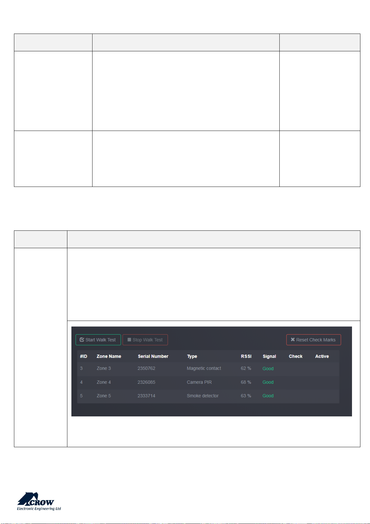
thecrowgroup.com
Page | 49
User Options
Parameter
Description
Default Configuration
Code Required to View
Memory
If this option is selected, access to view Memory Log, Status
Window and Active Time Zones will only be allowed by using an
authorized code.
If this option is not selected, anyone can access the memory in
disarm mode.
At Arm or Stay Arm modes, entering the code is required in any
case.
Not selected
Cancel Handover Zone
Function in Stay Mode
If this option is selected, any zone programmed with the
handover feature will act as a normal delayed zone during Stay
mode (i.e. the handover feature will be ignored).
The zone will still have the normal handover feature during the
full arm state.
Not selected
Walk Test
Parameter
Description
Walk Test
This option is used to start walk-test mode while in installer or user program mode
Press "Start Walk Test" button to start the test.
By cross-walking all of the detectors connected to the system and activating them, the associated zone
will latch up to allow verification that all zones are working properly.
Press "Exit & Stop Walk Test" button, the walk-test mode will be terminated.
The results of the walk-test will be displayed on the screen to verify which detectors were triggered
during walk-test mode.
Page 51
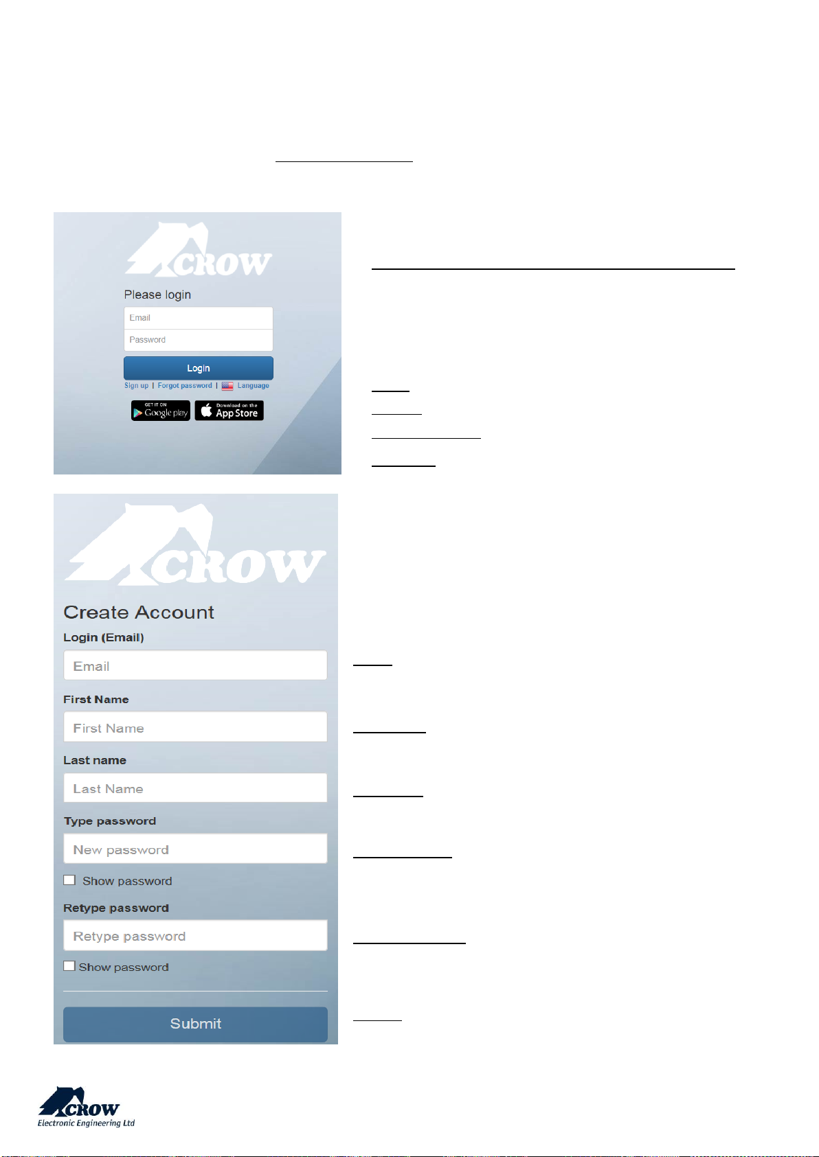
thecrowgroup.com
Page | 50
CrowCloud™ Web Services
Your Shepherd™ panel is configured by default for direct communication to CrowCloud™.
After configuration of your panel, go to http://Crowcloud.com and proceed with the user registration to your Shepherd™
panel.
The Crow Cloud personal user webpage give to the end user direct
access to all of its registered control panels.
This personal webpage offers to the end user possibility to:
Connect to its registered control panel
Monitor and Control panel and connected devices
Browse alarm pictures and request for immediate take picture
Get panel connection info
Manage cloud users
Login: If you already have an account on Crow Cloud, fill these form
Sign up: Click this link to start registration of new user
Forgot Password: Click this link to retrieve your password
Language: Select your preferred language
Email:
Enter end user email address.
First Name:
Enter the first name of the email address contact
Last Name:
Enter the family name of the email address contact
Type password:
Enter the password for connection to personal webpage
Retype password:
Confirm the password entered above
Submit:
Click this link to send form and create the user
Page 52
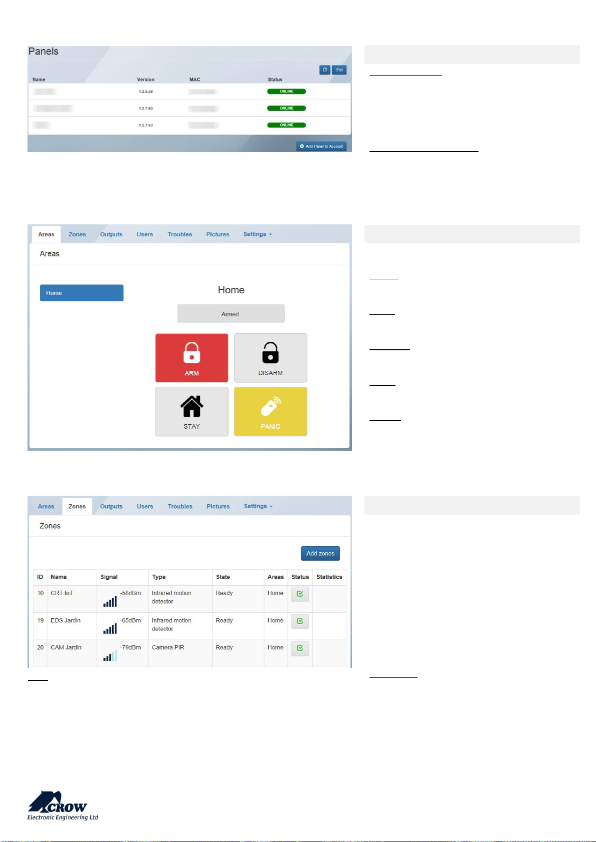
thecrowgroup.com
Page | 51
Click on the desired control panel to access to its monitoring and control
Welcome page of the CrowCloud™
Information on:
Name of registered control panels
Firmware version
MAC address of control panels
Current Status of control panels
From this page you can:
Edit list of registered control panels
Add new control panel to user
Areas
This part gives control to Shepherd™ panel
Areas:
Selection of the area to monitor/control
ARM:
Arming of the selected Area
DISARM:
Disarming of the selected Area
STAY:
Stay Arming of the selected Area
PANIC:
Press 5 sec to generate immediate Panic
Alarm
Note: Only active zones will be listed
Zones
This part gives info/control on Zones
Names of the active zones
RSSI Signal of the zone
Type of connected device
State of the device
Related area of the zone
Status (Active/Bypass) of the zone
Statistic (if device compatible) for
Temperature, Air Quality, Humidity…
Add Zones: online learning of devices
Page 53
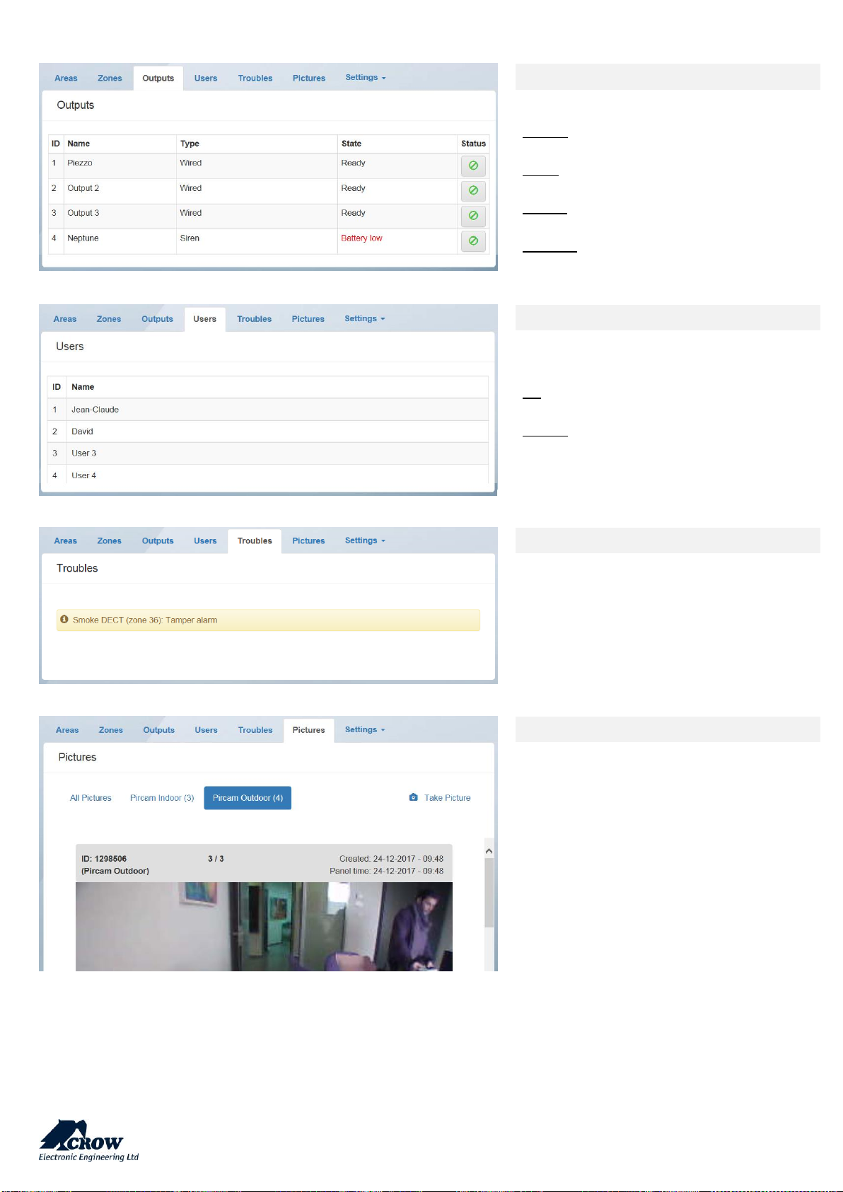
thecrowgroup.com
Page | 52
Outputs
This part gives control Outputs
NAME:
Name of the outputs (ex: outdoor siren)
TYPE:
Type of Output: Wired, Siren, Smart Plug…
STATE:
Info on output trouble
STATUS:
Activation / Deactivation of the output
Users
List of active users into the control panel.
ID:
User position registered in control panel
NAME:
Name of the user saved in control panel
Troubles
Information on current troubles detected
Pictures
This part of the personal page gives to the
end user information and control of
connected PIRCAM detectors with the
possibility to display pictures of all devices or
select device from which you want to see
saved pictures.
The End-User has also the possibility to Take
Picture from selected PIRCAM detector.
Page 54
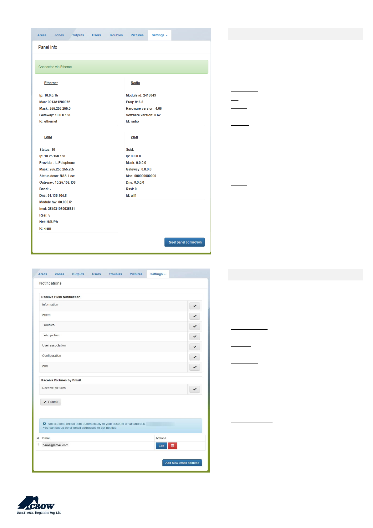
thecrowgroup.com
Page | 53
Panel Info
This part gives info on current
communication status:
Display of the current connection method
Ethernet:
IP: internal IP of the panel in your network
MAC: Ethernet MAC of the Shepherd™
Mask: Network subnet mask
Panel: IP of the router
ID: Name of the communication method
Radio:
Information on the Two Way wireless RF
module for wireless ISM devices
GSM:
Information received from cellular provider
on the current GSM/GPRS connection
Wi-Fi:
Information on the Wi-Fi connection status
inside your personal network
Reset panel connection:
Restart panel communication methods
Details
You can easily set up events notifications and
select type of events sent to each emails
addresses registered
Information: All type of information.
Alarm: Alarm occurs
Troubles: When the panel reports troubles
Take picture: In case of picture is requested
User association: When a new user is
registered on the panel
Configuration: Enter in installer mode
Arm: When arming the system
You can also select which email is allowed to
receive alarm pictures.
Page 55
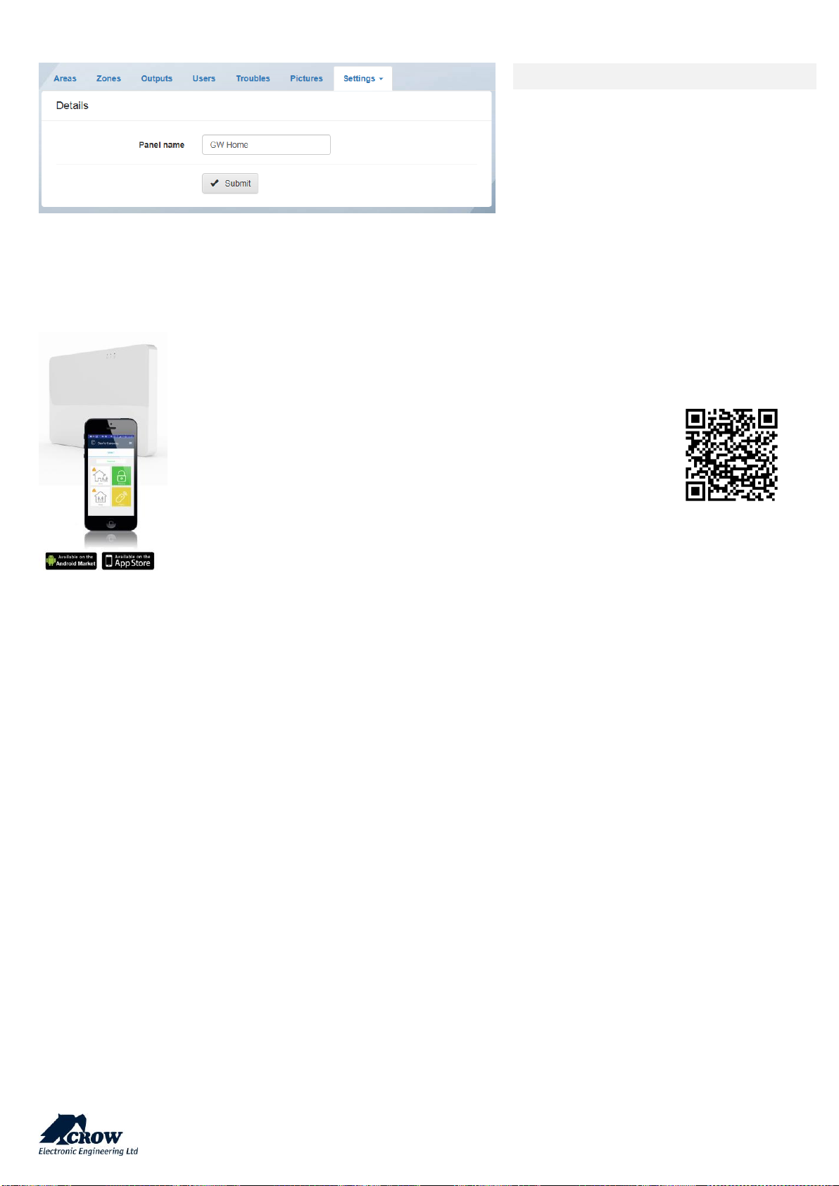
thecrowgroup.com
Page | 54
Details
This tab gives possibility to change control
panel name in the cloud
Mobile Applications
Friendly user guide will help you register and set up the Panel.
Install the Crow Pro application on your smartphone (iOS / Android)
or open your web browser http://CrowCloud.com
Page 56

thecrowgroup.com
Page | 55
All information and data contained in this document are proprietary and confidential. CROW Electronic Engineering Ltd. shall
not be liable, in any event, for any claims for damages or any other remedy in any jurisdiction whatsoever, whether in an
action in contract, tort (including negligence and strict liability) or any other theory of liability, whether in law or equity
including, without limitation, claims for damages or any other remedy in whatever jurisdiction, and shall not assume
responsibility for patent infringements or other rights to third parties, arising out of or in connection with this document.
Further, CROW Electronic Engineering Ltd. reserves the right to revise this publication and to make changes to its content, at
any time, without obligation to notify any person or entity of such revision changes. These materials are copyrighted and any
unauthorized use of these materials may violate copyright, trademark, and other laws. Therefore, no part of this publication
may be reproduced, photocopied, stored on a retrieval system, or transmitted without the express written consent of CROW
Electronic Engineering Ltd. Any new issue of this document invalidates previous issues.
©CROW Electronic Engineering Ltd. 2018. All rights reserved.
Information in this document is subject to change without notice.
No part of this document may be reproduced or transmitted in any form or by any means, electronic or mechanical, without
express written permission of CROW Electronic Engineering Ltd.
Page 57

thecrowgroup.com
Page | 56
Appendix 1: Installer Event log messages
AC Fail
Loss of AC power from the main panel
AC Restored
AC power restore on main panel
%O activated by %U
Output number %d activated by user number %U
%O activated by remote control
Output number %d activated remote control
*%Z Alarm in %A
Zone number %Z Alarm in Area number %A
Area Edited in %A by %S1
Area number %A label was Edited by Cloud user %S1
*%A Arm Failed
Area number %A arm operation failed
*%A Armed by Keypad %d
Area number %A armed via Keypad number %d
*%A Armed by Time Zone %d
Area number %A armed via Time zone number %d
*%A Arm Fail by Time Zone %d
Area number %A Arm fail by time zone number %d
Automatic Test Connect
Automatic communication test process finish successfully.
*%Z Bypass
Zone number %Z bypassed
*%Z Bypass Restore
Zone number %Z bypass restore
%U Bypass all Pendant Battery Low
User number %U is Bypassed all Pendants that at Battery Low
status
Code Attempts Alarm
False code alarm
Code Attempts Restore
False code alarm restore
Communication (%Y) Fail
Communication method (IP/ GPRS/Wi-Fi) (%Y) Fail
Communication (%Y) Restore
Communication method restore on main panel
Control Panel Added to User %S1, By %S2
Control Panel Added to Cloud user %S1 By Cloud user %S2
Control Panel Deleted from User %S1, By %S2
Control Panel Cloud user %S1 deleted By Cloud user %S2
Control Panel User Edited for %S1, By %S2
Control Panel Cloud user %S1 edited By Cloud user %S2
%O deactivated by keypad %d
Output number %O deactivated by keypad number %d
%O deactivated by remote control
Output number %O deactivated by remote control
DECT Delete Headsets by %S1
DECT Headset device deleted by Cloud user %S1
DECT Pair Canceled by %S1
DECT device pair cancel by Cloud user %S1
DECT Pair Started by %S1
DECT device pair process started by Cloud user %S1
%A Delinquency Alarm
Delinquency alarm in Area number %A
%A Delinquency Restore
Delinquency report Area number %A Restore
*%A Disarmed by %U
Area number %A disarmed by User number %U
*%A Disarmed by Keypad %d
Area number %A disarmed by keypad number %d
*%A Disarmed by Keyswitch %d
Area number %A disarmed by Keyswitch number %d
*%A Disarmed by Time Zone %d
Area number %A disarmed by time zone number %d
%U Duress Alarm
Duress Alarm from User Number %U
Duress Alarm Reset
Duress Alarm restored
Enter Installer Mode
Entering installer programing from installer web interface or
installer app.
Page 58

thecrowgroup.com
Page | 57
Exit Installer Mode
Exiting installer programing from installer web interface or
installer app.
*Fire Alarm from keypad %d
Fire Alarm from keypad number %d
*Fire Alarm Reset
Fire Alarm Restore
Full CFG View by %S1
Full configuration view by Cloud user %S1
*%Z 24 Hour Alarm
Zone number %Z 24 hour Alarm
*%Z 24 Hour Fire Alarm
Fire Alarm from Zone Number %Z
*%Z 24 Hour Fire Restore
24 Hour fire alarm restore zone number %Z
*%Z 24 Hour Restore
24 Hour alarm restore zone number %Z
*%Z Inactivity Alarm
Inactivity alarm from zone number %Z
*%Z Inactivity Restore
Zone number %Z inactivity alarm restore
Keypad %d Tamper
Keypad number %d tamper alarm
Low System Battery
Low battery fault from the main panel
*Medical Alarm from keypad %d
Medical alarm from KP number %d
*Medical Restore
Medical alarm restored
*%Z Near Alarm in %A
Zone number %Z near Alarm in Area number %A
*%Z Near Restore in %A
Near alarm restore zone number %Z in Area number %A
Output Deleted in %O by %S1
Output number %O deleted by Cloud user %S1
Output %d Fail
Output number %d operation failed
Output %d Tamper
Output number %d tamper alarm
*Panel Tamper
Panel Tamper alarm
Panel upgraded to new version
Panel upgraded successfully to new version
*Panic Alarm by pendant %U
Panic alarm by pendant User number %U
*Panic Alarm from keypad %d
Panic Alarm from keypad number %d
*Panic Alarm Reset
Panic Alarm Restore
*Pendant %U Battery Low
Low battery fault from pendant number %U
*Pendant %U Battery Restored
Pendant User %U Battery Restored
*Perimeter %Z Alarm in %A
Perimeter Alarm from Zone %Z in Area %A
*Perimeter %Z Restore in %A
Perimeter Alarm restore from Zone %Z in Area %A
Peripheral Battery Low
Battery Low was occurred in mail panel peripheral device
*Radio %O Battery Low
Low battery fault from output number %O
*Radio %O Battery Restored
Output number %O Battery Restored
*Radio %Z Battery Low
Low battery fault from Zone number %Z
*Radio %Z Battery Restored
Low battery restore fault from Zone number %Z
*%A Remote Disarm
Area number %A remote disarmed
*%A Remote Stay Arm
Area number %A remote stay armed
Report Channel %d failed
Report Channel number %d communication failed
%Z Restore in %A
Burglary alarm restore zone number %Z in Area number %A
RF module upgraded
RF module upgraded successfully
%A Stay Armed by Keypad %d
Area number %A stay armed by keypad number %d
%A Stay Disarmed by %U
Area number %A stay disarmed by User number %U
%A Stay Disarmed by Time Zone %d
Area number %A stay disarmed by time zone number %d
Supervised Radio %Z Restore
Supervision restore event from zone number %Z
System Battery Dead
Empty battery of the main panel
System Peripheral Trouble
Trouble was occurred in mail panel peripheral device
Page 59

thecrowgroup.com
Page | 58
System restarted
The control panel has reset
Take Picture in %Z Started by %S1
Take picture from PIRCAM Zone %Z started by Cloud user %S1
Take Picture in %Z Success
Take picture from PIRCAM Zone %Z Succeed
%Z Tamper
Tamper alarm from zone number %Z
%Z Verified Alarm in %A
Verified Alarm from Zone %Z in Area %A
Upgrade Failed by %S1
Panel upgrade failed by Cloud user %S1
Upgrade Started by %S1
Panel upgrade started by Cloud user %S1
User Deleted in %U by %S1
User number %U deleted by Cloud user %S1
Walk Test Started by %S1
Walk test started by Cloud user %S1
Zone Edited in %Z by %S1
Zone number %Z label was Edited by Cloud user %S1
Zone Params Edited in %Z by %S1
Zone number %Z parameters were Edited by Cloud user %S1
Zone %Z to Output %O Edited by %S1
Assign Zone %Z to Output %O was done by Cloud user %S1
* Event log display cannot be suppressed, as specified by EN50131-1-2006
Compliance Standards
EN/IEC 50131 Level 2
EN 301489-1
EN 301489-3
EN 301489-52
EN 61000-6-3
EN 50130-4
EN 300220-1
EN 300220-2
EN 62368-1
EN 50130-5
EN 50131-1
EN 50131-3
EN 50131-6
EN 50131-10
EN 50136-1
EN 50136-2
EN 50131-5-3
Certification body: Telefication B.V.
Pass-through operation feature:
The control panel working with pass-through mechanism.
The SPT shall not acknowledge the alarm to the AS before receiving an acknowledgement from the
RCT. When the SPT receives an acknowledgement from the RCT, the acknowledgement shall be
forwarded to the AS.
REDUNDANCY / DUPLICATION:
All events are transmitted and received via TCP/IP interface (primary). In case of primary channel fail, the event will be
transmitted via the secondary back-up channel (GPRS).
ATS UNAVAILABILITY:
The ATS sends all faults to ARC(s) in any case except case then the ATS unavailable due to maintenance by accredited person
with appropriate access level
 Loading...